
Abstract
Objective: The aim of this paper is to quantitatively investigate the thermal effects generated by the pre-focal interactions of a HIFU beam with a rib cage, in the context of minimally invasive transcostal therapy of liver malignancies. Materials and methods: HIFU sonications were produced by a phased-array MR-compatible transducer on Turkey muscle placed on a sheep thoracic cage specimen. The thoracic wall was positioned in the pre-focal zone 3.5 to 6.5 cm below the focus. Thermal monitoring was simultaneously performed using fluoroptic sensors inserted into the medullar cavity of the ribs and high resolution MR-thermometry (voxel: 1 × 1 × 5 mm3, four multi-planar slices). Results: MR-thermometry data indicated nearly isotropic distribution of the thermal energy at the ribs’ surface. The temperature elevation at the focus was comparable with the pericostal temperature elevation around unprotected ribs, while being systematically inferior, by more than a factor of four on average, to the intra-medullar values. The spatial profiles of the pericostal and intra-medullar thermal build-up measurements could be smoothly connected using a Gaussian function. The dynamics of the post-sonication thermal relaxation as determined by fluoroptic measurements was demonstrated to be theoretically coherent with the experimental observations. Conclusion: The experimental findings motivate further efforts for the transfer towards clinical routine of effective rib-sparing strategies for hepatic HIFU.
Introduction
According to the National Institutes of Health, ‘cancer is the leading cause of death in developed countries and the second leading cause of death in developing countries’. Liver cancer is a major public health issue and a considerable source of concern as the liver is a frequent site for both primary and secondary tumours [Citation1] – approximately 48 700 new cases and 43 300 deaths annually [Citation2] in Europe, i.e. an incidence and mortality rate of respectively 16/100,000 and 15/100 000. Metastatic tumour deposits occur most frequently in the liver. A significant proportion (50–70%) of patients diagnosed with colorectal cancer will later develop liver metastasis. Hepatic resection or liver transplantation are curative treatments for liver cancer in selected patients (e.g. 15% for hepatocellular carcinoma and 40% of colorectal metastases), but may have a high associated incidence of recurrence, even after multiple resections or ablations [Citation3,Citation4]. Hepatic metastases are also the major cause of morbidity and mortality in patients with gastrointestinal carcinomas.
High intensity focused ultrasound (HIFU) is a therapeutic approach that is both flexible and minimally invasive. The fundamental principle of HIFU treatment consists of inducing sharply delineated lesions around a focal point and deep within the tissue, while preserving intact all adjacent structures [Citation5]. Magnetic resonance imaging offers excellent anatomical delineation of tumours and is capable of measuring post-treatment functional changes and predictors of treatment success, such as non-perfused volumes (NPV) [Citation6]. Overall, MRI provides excellent capabilities for spatial guidance and on-line control of HIFU therapy and is currently the only validated technique for non-invasive temperature measurement within biological tissue. MR thermometry (MRT) based on the proton resonance frequency (PRF) shift versus temperature provides a tissue-independent, linear method to measure the relative temperature change in tissue from the physiological baseline to the boiling point [Citation7,Citation8]. Online temperature maps can be used for active feedback control of the HIFU treatment [Citation9–11]. Preparatory MR-ARFI maps are an elegant adjunct for in situ confirmation of precise focusing before the ablative sonication [Citation12–14].
Various reports are available describing feasibility studies [Citation15,Citation16] or established clinical applications [Citation17] of minimally invasive ablation using extracorporeal HIFU. There are, however, significant challenges associated with the application of magnetic resonance-guided HIFU (MRgHIFU) for the treatment of abdominal organs (such as the liver, pancreas or kidney) due to (1) motion-related proton resonance frequency shift (PRFS) thermometry artefacts, (2) moving target location caused by breathing and (3) the need for a high acoustic power output to compensate for high perfusion and a restricted acoustic window. There thus exists a high risk of side effects caused by undesired heating in the near and far field. For the treatment of patients with unresectable liver metastases and hepatocellular carcinoma, MRgHIFU is potentially an innovative local ablative therapeutic alternative. However, very few hepatic MRgHIFU treatments have been reported [Citation18–20], despite the large number of patients potentially eligible for such a treatment. Furthermore, in each of the previously cited reports, the subxiphoid acoustic window was used, excluding intercostal sonication. Therefore, to the best of our knowledge, MR thermography data for HIFU-induced rib heating in patients is not yet available. Importantly, in experimental models, HIFU was demonstrated to be clearly superior to RFA in coagulating tumours close to major blood vessels because of the shorter time scale and mm range accuracy of the heat deposition [Citation21].
One of the main challenges for transcostal HIFU therapy in abdominal organs is avoiding the known high risk of collateral heating and thermal damage to the ribs and the tissue surrounding the ribs. In a clinical study by Jung et al. [Citation22], the MR follow-up of US-guided intercostal HIFU treatment indicated systematic lesions of the rib cage. All hepatic tumour patients had necrosis of the ribs along the main ultrasound beam path. Delayed complications in hepatic tumour patients included a diaphragmatic rupture and rib fractures along the ultrasound pathway [Citation22]. Several methods have been proposed to solve this problem, using either US or MR guidance; however, none of the solutions below have yet been evaluated under clinical conditions:
Design of a linearly segmented transducer with elements arranged in strips and with selective deactivation of edge elements [Citation23].
Similar to Civale et al. [Citation23] but using 2D phased array, selective deactivation of emitting elements that fall in the shadow (conical projection) of the ribs has been investigated [Citation24,Citation25].
Adaptive focusing using multi-element transducer devices capable of working in both transmit and receive mode [Citation26,Citation27].
Synthesis of multiple-focus ultrasound heating patterns through the human rib cage [Citation28] based on a hybrid ray-physical optics (HRPO) model.
MR-guided external shielding of acoustic obstacles (e.g. the ribs) was investigated to avoid unwanted pre-focal energy deposition in the pathway of the focused ultrasound beam [Citation29]. A physical mask was inserted in the pre-focal beam pathway, external to the body, to block the energy normally targeted on the ribs.
Non-linear propagation in a high-intensity focused ultrasound (HIFU) field produced by a therapeutic phased array [Citation30] which may yield an increase in heating of tissue behind a rib cage.
Rather than suggesting novel methods for rib sparing during intercostal HIFU sonication, the aim of this current study was to investigate in-depth the thermal effects generated by the HIFU beam’s interaction with the rib cage. The diameter of the ribs and the spacing between the ribs are several times larger than the acoustic wavelength of the applied HIFU beam; however, the diffraction effects are still significant and any rib-sparing method (e.g. beam shaping, shielding, element deactivation) can only partially reduce the rib heating during sonication. Understanding and modelling the underlying phenomena when the rib cage is exposed to the pre-focal HIFU field at a more fundamental level may also help when defining guidelines and criteria for treatment safety.
The present study was motivated by preliminary findings reported by both ourselves and other research groups. For example, in (p. 189) of the cited report [Citation22], the shape of the contrast agent uptake is circular around the perimeter of the exposed ribs (visualised 2 weeks post-treatment). That geometry of rib lesion is not indicative of the direction of the incident HIFU beam; that is, the lesion on the external facet of the rib (side facing towards the emitting HIFU transducer) is not more significant than the lesion found on the internal facet (side facing towards the diaphragm and liver). Similar findings were reported in experimental studies using online MR thermometry by Salomir et al. [Citation29], of most interest are (p. 374), 7F (p. 375) and 9E–F (p. 377). The thermal build-up around the sonicated ribs, in a plane perpendicular to those ribs, appears to be radially symmetric in first approximation (within 10% range), for various conditions (ex vivo, post-mortem animal and in vivo animal). From the published data it can be seen that the external and internal facets of the rib underwent similar temperature elevation during the sonication. This was confirmed with follow-up imaging ([Citation29], Figures 8C–D) (p. 376) and post-mortem gross pathology ([Citation29], Figures 8A–B) (p. 376), which demonstrated burning of the liver capsule and parenchyma due to rib contact and fibrotic attachment of the parietal surface of the liver to the thoracic wall.
One purpose of this work was to investigate the pericostal thermal effects more systematically and in a quantitative way. Another purpose was to obtain ‘gold standard’ temperature data from the medullar cavity inside the rib during HIFU sonication, knowing that MR methods of thermography within bone marrow are under development [Citation31] and not yet fully validated.
We therefore conducted MRgHIFU studies on phantoms and ex vivo tissue to enable in-depth characterisation of the thermal effects at and around the ribs lying in the HIFU near field (or pre-focal) using fluoroptic sensors inserted inside the rib’s medullar cavity.
Material and methods
Instrumentation
Magnetic resonance guided high intensity focused ultrasound (MRgHIFU) studies were conducted using a whole-body 3T MR scanner (MAGNETOM Trio, A Tim system; Siemens, Erlangen, Germany, maximum gradient strength, 45 mT/m). A receive-only, single channel, loop coil of 11 cm diameter was used for MR data acquisition for experiments without rib protection, while a dedicated interventional 3-channel coil (Clinical MR Solutions, Brookfield, WI) with a central aperture enabling HIFU beam propagation was used for experiments with rib protection [Citation29]. In the latter case, the HIFU beam propagated through this coil aperture. The HIFU device consisted of a phased array (256 elements) MR compatible transducer (Imasonic, Besancon, France) operating in the frequency range 974–1049 kHz, with natural focal length (radius) F = 130 mm and aperture D = 140 mm (F/D number = 0.93), driven by a programmable 256-channel generator and a 2D positioning mechanism in the coronal (OxOz) plane with 0.5-mm accuracy (both from Image Guided Therapy, Pessac, France). The HIFU transducer was placed horizontally on the MR table and emitted vertically. The focal point position could be changed by electronic steering in a −3 dB revolution ellipsoid of axes 30 mm Ox, 30 mm Oz and 50 mm Oy around the natural focus. HIFU treatment planning and hardware control was achieved using Thermoguide™ software (Image Guided Therapy). Further details concerning the HIFU platform are provided in the study by Auboiroux et al. [Citation32].
Four MR-compatible fluoroptic temperature sensors (STF-5, Luxtron, Santa Clara, CA, USA) were used to obtain a ‘gold standard’ temperature measurement, performed synchronously to MR thermometry measurements (see below). The optical fibre (0.8 mm diameter, 5 m long) terminated with a temperature-sensitive, fluorescent tip having a 0.5 °C accuracy guaranteed by the manufacturer in the range of 0–295 °C. The fluoroptic thermometry system (FOT LabKit, Luxtron), placed outside the MR room, was used to record the temperature of the optical probes. Measurements were recorded every second for each fluoroptic sensor using the associated software to interface with an external PC via the standard serial port.
MR thermometry
The Proton Resonance Frequency Shift (PRFS) thermometry [Citation7,Citation33] method was used for high resolution measurement of the temperature elevation in the tissue (voxel size 1 mm × 1 mm × 5 mm) during each experiment. A conventional radiofrequency-spoiled segmented EPI gradient echo sequence (GRE-EPI) was implemented similar to Viallon et al. [Citation34]. Three or four interleaved slices were acquired using the following main parameters: echo train length = 5, TE (echo time) = 11.2 ms, TR (repetition time) = 32.2 ms, FA (flip angle) = 12°, BW (bandwidth) = 400 Hz/pixel, acquisition matrix 128 × 128, water selective excitation using second order binomial pulses ‘1-2-1’, no partial Fourier undersampling, temporal resolution 4 s. The orientation of the slices was adapted to the set-up and is described in the next section.
Preliminary in vitro study
An initial feasibility experiment was conducted in vitro in order to verify whether the spatio-temporal and temperature resolution envisaged are appropriate for monitoring the heating of a cylindrical structure with a mm-range thick wall. Our experimental tests on various materials (data not shown) indicated that sonicating a plasticised semi-flexible PVC (PVC-P) tube (Tubclair, Tricoflex, Rueil Malmaison, France) can mimic the temperature elevation around an ex vivo rib positioned in the HIFU near field. A segment of PVC-P tube of inner diameter 12 mm and wall thickness 2 mm was embedded in a 3-cm thick layer of 15% poly-methylmethacrylate (PMMA) gel [Citation35]. Once the polymerisation of the PMMA gel had finished, the tube was filled with degassed water and placed in the pre-focal zone (approximately 5 cm below the focus), then sonicated (180 W, 36 s) in order to observe the thermal build-up around the obstacle. MR thermometry was performed with three orthogonal slices (coronal, sagittal, transverse). The coronal plane was set at the level of the focus, which was positioned in ex vivo degassed turkey pectoral muscle, placed on top of the PAAM gel as a propagation medium. The transverse plane contained the longitudinal axis of the PE tube and the focal point. The sagittal plane therefore cut the tube perpendicularly. PRFS thermometry data was collected in the PAAM gel around the tube, but not at the tube wall itself nor in the water filling the tube.
Ex vivo studies
Intercostal HIFU treatments were performed ex vivo by placing degassed turkey pectoral muscle on a sample of freshly excised and degassed sheep thoracic cage. The ex vivo thoracic wall was positioned directly on the membrane of the HIFU transducer’s water tank, or supported by polystyrene foam with an appropriate aperture, depending on the prescribed pre-focal height. Acoustic coupling was achieved using standard ultrasonic gel and degassed deionised water.
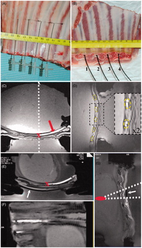
Prior to sonication, four fluoroptic fibres were inserted into the medullar cavity of four successive ribs. In order to achieve this, the medullar cavity was first perforated longitudinally using a 16-gauge/7 cm needle (Cook Medical, Bloomington, IN), see . Special care was taken to avoid perforating the cortical bone of the ribs. Secondly, after removal of the perforating needle, an identical needle was inserted back into the empty ‘tunnel’ created, in order to rinse this space with an MR contrast agent solution (1% gadolinium-DTPA, Dotarem, Guerbet, France) for MR image tagging. The tagging solution was slowly injected while retracting the needle, while maintaining the rib cage specimen vertical with the needle tip pointing up. This manipulation was necessary in order to avoid contamination of tissue elsewhere with the MR contrast agent. Note that if the cortical bone is perforated, the contrast agent would leak into the interstitial space compromising the ulterior MR image tagging. Thirdly, one optical fibre was carefully inserted into the medullar cavity of each rib, see , until the fluoroptic tip reached the end of the ‘tunnel’ impregnated with MR contrast agent. Thus, the position of the fluoroptic sensor was easily determined from high resolution isotropic 3D MR T1-weighted images as shown in acquired with a gradient-echo sequence (volume-interpolated breath-hold examination VIBE) with the following parameters: TE/TR/time of acquisition/FA/BW, 1.6 ms/4 ms/2.55 min/10°; 650 Hz; and spatial resolution of 0.9 × 0.9 × 0.9 mm3. Placing fluoroptic sensors on the surface of the ribs was not performed in this study because of experimental difficulties in accurately tracking them outside the ribs. The tagging method was not applicable outside the rib because the contrast agent solution tends to spread to various tissue interfaces. Nevertheless PRFS-based MR thermometry was considered a reliable method within the pericostal soft tissue.
Figure 1. Set-up of ex vivo sample using ‘gold standard’ MR-compatible fluoroptic temperature sensors. (A) Perforating needles inserted into the ribs. (B) Optical fibres (numbered 1 to 4) inserted into the medullar cavity ‘tunnel’. (C) Transverse oblique section in the T1w 3D MR data visualising tagged ‘tunnel’ (see red arrow) in which the fluoroptic sensor was positioned. Note the dotted white line indicating the position of the sagittal slice for MR thermometry tangent to the tip of the tunnel. The location of the fluoroptic probe measurement (the tip of the probe) is identified with red ‘x’ symbol. (D) Sagittal section in the T1w 3D MR data visualising the orthogonal section of the ribs (see dotted yellow ellipses), which were positioned in the pre-focal HIFU zone. (E) Similar to C, but an external mask (white arrow) is visible below the imaged rib, for acoustic shielding. (F) Curved interpolated slice reconstructed from the T1w 3D MR data for a pseudo-planar representation of the thoracic wall and the rib cage. (G) Gradient echo FLASH 2D image orthogonal to the ribs, illustrating the protector (see white arrow indicating the signal void area) aligned using a conical projection from the focal point. Fields of view shown are 128 × 128 mm2 (C), 140 × 140 mm2 (D) with zoom-in insert box by a factor of 2, and 220 × 110 mm2 (G).
The symmetry axis of the HIFU conical beam was prescribed to be intercostal, equally distant from two centrally exposed ribs. Single focal point sonications were performed at different levels of acoustic power and different durations (see ). The distance between the focal point and the centre of the ribs (i.e. pre-focal height) ranged between 3.5 and 6.5 cm.
Table 1. Overview of the experimental results. The distance from the rib’s central axis to the focus was 3.5 cm (A and B), 6.5 cm (C) and 5.5 cm (D).
MR thermometry was performed with four orthogonal slices (two coronal, one sagittal and one either transverse or transverse oblique to coronal). The 3D MR T1-weighted data was used as background images for planning. One coronal slice (i.e. horizontal) was set to pass through the focus and another one through the best plane following the ribs, which are systematically incurved. The sagittal slice cut the ribs perpendicularly. This was precisely aligned to be tangent to the end points of the tagged ‘tunnels’, as visualised inside the ribs. Note that this registration is essential in order to guarantee that the sagittal MR thermometry slice and the fluoroptic thermometry sensors are correctly matched spatially, necessary for the interpretation of results. As the acoustic intensity varies as a spatially smooth function in the pre-focal region (ribs lying 3.5 to 6.5 cm below the focus), slight misalignment here or partial volume effect due to the finite MR slice thickness is not critical within a range of a few millimetres. The transverse MR thermometry slice symmetrically cut the intercostal space between the two ‘central’ ribs. If prescribed, the transverse oblique MR thermometry slice was jointly determined by the focus and one ‘central’ rib, thus directly visualising the thermal build-up along that rib. PRFS thermometry data was collected in the pericostal tissue and the top muscle, but not at the cortical or medullar bone of the rib where the T2* (uncoherent gradient echo transverse relaxation time) value was too low. The temperature time plots at the rib’s facets (internal and external) were generated by spatially averaging the PRFS-induce phase shifts in the voxels adjacent to the rib’s hyposignal (saggital slices) where the signal-to-noise (SNR) was superior to 5, proximal and respectively distal with respect to the HIFU transducer. Synchronised temperature measurement inside the rib medullar cavity using fluoroptic sensors was recorded during MR thermometry.
Optionally, a physical mask was inserted into the beam pathway, pre-focal and external to the sample in order to protect one of the two ‘central’ ribs directly exposed to the beam pathway, according to Salomir et al. [Citation29], see . The reflective material used for the shielding was engineered to scatter the incident beam and thus to block the energy normally directed to the rib. The multiple-step procedure for MR-guided alignment of the reflective strips with the conical projection of that rib is described in detail in Salomir et al. [Citation29]. Finally, a 2D slice gradient echo sequence (GRE) FLASH was acquired (TE = 10 ms, 0.5 mm in-plane resolution, 5 to 10 mm slice thickness, acquisition time 40 s), containing the prescribed position of the focal point and orientated perpendicular to the ribs, in order to control the accurate alignment of the protector, see . Note that the local cylindrical symmetry of both the rib and protector enables one to use thick perpendicular slices without loss of information and with improved SNR.
Results
In vitro pre-focal cylindrical obstacle interacting with HIFU
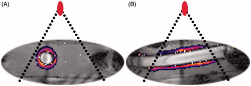
Using the ‘ideal geometry’ phantom (i.e. PVC-P cylinder), PRFS MR thermometry showed isotropic thermal build-up (circular isotherms) around the perpendicular section of the obstacle, see . It is acknowledged that the thermo-acoustic parameters are individually different between ex vivo rib and PVC-P tube [Citation36]; however, the thermal build-up resulting from the parameter combination was found to be representative. These thermal patterns were rotationally invariant with respect to the direction of the incident HIFU beam. They reproduced the qualitative findings for animal and human ribs exposed to HIFU beams as reported by Salomir et al. [Citation29] and Jung et al. [Citation22]. Heating patterns along the long axis of the obstacle were mainly parallel to that axis, see , emphasising similar temperature elevation along the obstacles proximal or distal (with respect to the HIFU transducer) facet inside the beam cone.
Figure 2. In vitro investigation of thermal build-up around a 10-mm diameter PE tube filled with degassed water, embedded in PAAM gel and positioned in the pre-focal HIFU zone at 5 cm below the focus. Sagittal (A) and transversal (B) views of the PE tube are illustrated. Overlaid drawings indicate the HIFU beam cone and the focal point position for the set-up. The temperature elevation map colour code ranges from +4° to +30 °C.
Ex vivo pre-focal thoracic wall interacting with HIFU
The first important observation, evident in every experiment performed, was the near-isotropic distribution of the thermal build-up around the pre-focally sonicated ribs, measured in the perpendicular sections (see ). A second important observation, applicable to all situations where the ribs were unprotected, was that the pericostal temperature elevation was comparable to the focal point temperature elevation, the latter being significantly always inferior to the temperature elevation measured inside the rib medullar cavity (see ). A third observation, again valid for every experiment performed, concerns the spatial profile of the hybrid measurement of fluoroptic/MR temperature elevation at and, respectively, around the rib in the perpendicular plane. That is, a Gaussian shape can smoothly connect the pericostal measurements acquired using MR thermometry to the intra-medullar measurement acquired using the fluoroptic sensor, the latter representing the central peak value of the Gaussian function, see . A synthesis of the ex vivo results is presented in .
Figure 3. Temperature elevation maps illustrating the end point of the HIFU sonication in three different experiments (one per row), with PRFS data overlaid on GRE-EPI magnitude images. The acoustic power and duration were respectively (A–D) 70.3 W, 30 s, (E–H) 180 W, 30 s, (I–L) 137.8 W, 60 s. A low energy pilot sonication is shown in frames A–C, used for confirming the alignment of the slices. The definition of the external and internal rib facets is illustrated in frame D where the elliptical focal shape is also drawn. Frames A and E show transverse slices passing between two ‘central’ ribs and frame I is a transverse-oblique slice passing through a sonicated rib. Frames H and L are zoom-in of frames F and J, respectively, by a factor of 3, demonstrating the symmetry of the thermal build-up around the heated ribs. Note in frame H the locations of the time temperature profiles that are further plotted in : internal facet ΔT(I) and external facet ΔT(E)). In frames F and H one rib proximal to the acoustic beam axis was protected with external shielding. White arrows indicate the incidence direction of the HIFU beam. The temperature colour bar is provided in the right column, one per row. The field of view of the frames shown excluding the last column is 128 mm2.
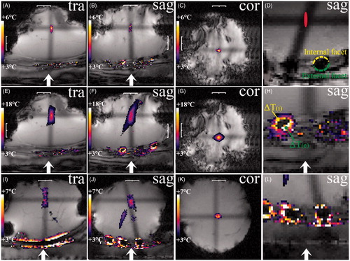
Figure 4. Plots of the temperature elevation measured at the focal point (red), at the external (blue) and internal (green) facets of the rib using MRT, and inside the medullar cavity of the rib using the fluoroptic sensor (black), for various measurement conditions. The sonication acoustic power and duration parameters were, respectively, (A) 180 W, 30 s; (B) 180 W, 30 s, (C)137.8 W, 30 s, (D) 137.8 W, 60 s. External shielding of one rib is indicated in (A) see dotted line, and all other curves plotted with continuous line were recorded for unprotected ribs. The black arrow in A indicates a discontinuation of the first order temporal derivative of the thermal relaxation curve inside a shielded rib.
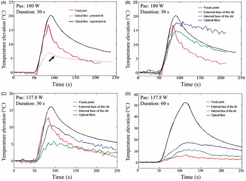
Figure 5. Illustration of 1D profiles of the thermal build-up through unprotected ribs in different experiments, along a direction perpendicular to the propagation axis of the HIFU beam and corresponding to the sonication end point: (A) 30 s, and (B) 60 s. The perpendicular section of the rib is qualitatively illustrated. *Pericostal temperature elevation data are obtained from PRFS thermometry in the axial plane. The blue ‘o’ denotes where the highest point of the Gaussian fit was constrained according to the intra-medullar fluoroptic sensor data.
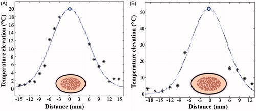
Figure 6. Experimental plot of the left hand side of Equation 8 as a function of the post-sonication time lapse (Δt). Fluoroptic sensor data during thermal relaxation inside the unprotected rib was obtained in the same experiment as shown in . The dotted line corresponds to the slope at the origin expressed in Equation [9].
![Figure 6. Experimental plot of the left hand side of Equation 8 as a function of the post-sonication time lapse (Δt). Fluoroptic sensor data during thermal relaxation inside the unprotected rib was obtained in the same experiment as shown in Figure 5(A). The dotted line corresponds to the slope at the origin expressed in Equation [9].](/cms/asset/616f9977-669e-4ba4-ae49-c369d0c4afa6/ihyt_a_1009501_f0006_c.jpg)
The ratio between the temperature elevation at the external rib facet versus that at the internal rib facet, determined from 30 independent experiments using pericostal MR thermometry, was found to be 1.15 ± (SD) 0.33, see . This result indicates a slight tendency for preferential heating at the external facet (with respect to the HIFU transducer) (see ), however, it is not statistically significant. Overall, the external and internal facets of the ribs and their respective adjacent structures should be considered as being exposed to similar risks during intercostal MRgHIFU ablation.
Moreover, the ‘gold standard’ temperature elevation measured inside the medullar cavity of the rib by the fluoroptic sensor was significantly higher than the value estimated in the pericostal tissue by MR thermometry (measured in a soft tissue layer, as close to the rib as possible while maintaining sufficient SNR). The ratio between the true intra-medullar temperature elevation and the nearest pericostal MR thermometry estimation, determined from 18 independent experiments with varying values for acoustic power and duration, was found to be 4.16 ± 2.84 (SD), with a minimum–maximum range of 1.4–9.9.
For the rib protected using external mask shielding, the temperature elevation measured inside its medullar cavity was significantly lower than on the unprotected rib (see , then sample D), a reduction factor of 3.45 ± 0.36 (SD).
The use of rib shielding yielded a discontinuation of the first order temporal derivative of the cooling temperature curve recorded by the intra-medullar sensors (see arrow in ). As the medullar cavity is centrally masked by the protector and therefore optimally shadowed from the HIFU beam, little energy is directly deposited there and this energy rapidly dissipates after the sonication end point. This initial ‘intrinsic’ relaxation corresponds to the first segment of the post-sonication temperature curve that drops off relatively rapidly. Further relaxation is limited by the surrounding temperature of the unshielded pericostal tissue that was weakly and directly heated by the HIFU beam.
Discussion
This study was aimed to explore in depth the thermal phenomena generated by pre-focal interactions between a HIFU beam and the rib cage. High resolution multi-planar MR thermometry and intra-medullar fluoroptic sensors were used for this purpose. We investigated quantitatively and confirmed here the phenomena involved in pericostal thermal lesions that were qualitatively reported previously by Jung et al. and Salomir et al. [Citation22,Citation29].
We report near isotropic heating of the rib perimeter in the perpendicular section, which appears to be insensitive to the direction of the incident beam within that plane. Therefore, structures located behind the rib cage (e.g. diaphragm, liver) would suffer serious thermal lesions in places where they are in contact with the rib, if no rib-sparing strategy is used.
In this study, the focal point temperature elevations were low to moderate, as the delivered acoustic energy was deliberately limited to avoid heating the intra-medullar rib above 100 °C. indicates the relative changes in temperature; the absolute intra-medullar temperature measured in this study did not exceed 80 °C when integrating the room temperature baseline. Temperatures greater than 100 °C should be avoided as tissue vaporisation would modify the physical process involved, as well as introducing potential PRFS thermometry artefacts.
An important observation arising from this study concerns the use of the pericostal PRFS temperature estimation in soft tissue adjacent to the rib as a measure for the thermal risk of the rib itself. When comparing the pericostal thermometry with the true intra-medullar temperature provided by the ‘gold standard’ sensors, a significant difference is noted, greater than a multiplicative factor of 4 on average. This implies that PRFS temperature monitoring in the pericostal soft tissue should be performed very conservatively, as the true temperature inside the rib is much higher. An important question is whether the fluoroptic sensor indicated the real temperature of the medullar bone, or whether this measurement was biased, for example due to direct ultrasound absorption and thus heating of the sensor above the true temperature of the biological tissue. To eliminate potential misinterpretation we have analysed the cooling curve of the temperature with respect to time as provided by the sensor after the sonication end point, see the Appendix for details. Given the small size of the sensor tip (less than 1 mm) and the known thermal diffusivity in bone (0.24 mm2/s) [Citation37], the thermal specific relaxation time of the sensor tip, if immersed in a colder environment, must be very short; this was not observed in our studies. The experimentally observed relaxation time of the temperature, measured by the fluoroptic sensor without rib shielding, closely matched the theoretical prediction for the dissipation of a Gaussian thermal build-up for the size of ribs used in our experiments. Another argument that substantiates the sensor data is that a Gaussian shape can be fitted to the spatial profile of the temperature, smoothly connecting the pericostal PRFS measurements with the value provided by the sensor, which represents the central height of the Gaussian function (see ). A subsequent conclusion is therefore the existence of a steep temperature gradient at the cortical bone layer of the rib, a value as great as 10 °C/mm was measured in our experiments. The existence of such strong temperature gradients would be a potential source of MR thermometry underestimation according to Todd et al. [Citation38] if finite resolution MR thermometry was performed directly in the rib.
As the temperature rises simultaneously pericostally and intramedullarly (see ), i.e. no reciprocal time delay, with the highest temperature elevation being inside the rib over the pericostal region we can conclude that the acoustic energy penetrates the rib and directly heats the osteal tissue. In our non-perfused ex vivo model, the temperature elevation inside the rib exceeded the temperature elevation at the focus, for rib to focus distances ranging from 3.5 to 6.5 cm and using a spherical transducer of F-number equal to 0.93.
The original report describing the method for external shielding of ribs [Citation29] measured a reduction factor of thermal deposition on ribs of 3.3 ± 0.4 (SD) based on pericostal MR thermometry average estimations. For the present study, the protecting effect was assessed using ‘gold standard’ sensors inserted inside the ribs, as illustrated in , and the reduction factor of the intra-medullar temperature elevation 3.45 ± 0.36 (SD) was found to be very close to the initial value.
Numerical modelling of the physical interactions between the pre-focal HIFU beam and the rib cage was beyond the extent of this report, considering that, to the best of our knowledge, limited information has been published on the fundamental physics involved. One recent report [Citation39] calculated acoustic pressure distributions and heat dissipation patterns to evaluate the safety limits using combined electronic steering and the binarised apodisation law for phased array element excitation during intercostal liver ablation. The model was based on a discretisation of the linear acoustic wave equation in heterogeneous absorbing media, including mode conversion into share waves [Citation40]. Their calculations (see Figure 12 in Marquet et al. [Citation39]) suggest that electronic steering influences the maximum temperature at the rib; however, they did not predict the internal/external symmetry of rib heating, e.g. the similar thermal history of the internal versus external rib facet, as experimentally measured here.
In an experimental study on non-embalmed human adult cadavers, Abrams et al. measured the geometric parameters of the cross sections of ribs three to nine [Citation41]. The typical range of the height and width of each cross section was found to be 6–8 mm and 11–13 mm respectively, with a through-population standard deviation of approximately 25%. Similar values are provided in Mohr et al. [Citation42]. Our ex vivo sheep specimen had typical height and width cross sections in the range of 5–6 mm and 9–11 mm respectively, see . These values are smaller but nevertheless similar to an adult patient case. The intercostal space (12.3 ± 2.9 mm [Citation43]) for adult humans is similar to that of the sheep thoracic cage used in this study (12 to 16 mm).
Our present results are not considered to be directly transposable as they are to other larger bones (e.g. femur, pelvis) potentially concerned by palliative MRgHIFU ablation of bone metastases. Ribs have a particular anatomy with a thin cortical bone, whose thickness is in the order of 1 mm for human ribs [Citation41, Citation42] as well as for our experimental ex vivo set-up. Considering the shear sound speed = 1500 ± 140 m/s and longitudinal sound speed = 2820 ± 40 m/s in cortical bone [Citation44] the respective acoustic wavelengths at 1 MHz are greater than the thickness of the rib cortical bone, possibly involving evanescent waves.
Considering the abdominal ablation of a patient using extracorporeal HIFU in clinical conditions, respiratory motion would mainly affect the target region, with little or no motion of the rib cage, depending on the posture of the patient [Citation45,Citation46]. Since the acoustic pressure has a smooth spatial profile in the pre-focal region, local motion of the ribs relative to the HIFU beam would not have a significant effect on their accumulated thermal build up. The thermal contrast between the focus and rib in vivo using active tracking of motion in the liver will be worse than that reported in our static ex vivo results, due to imperfect target motion tracking caused by finite temporal and spatial sampling.
Although our set-up involved ex vivo samples, ‘active’ heat sink at the tissue layer proximal to the transducer occurred during sonication as the acoustic radiation impulse induced streaming in the coupling water. To achieve a more sustained active cooling, dedicated devices for active surface cooling should be integrated into the therapy set-up. Such approaches are mostly of interest for skin protection and may have limited efficacy for deeper tissues, especially when highly absorbent such as the rib cage.
Some limitations of the present study have been identified. The achievable MR thermometry resolution using a clinical 3T MR scanner and standard loop coil was limited to 1 mm in plane. This is significantly smaller than the size of a perpendicular section through a rib (6 to 10 mm); however, the effect of discrete spatial sampling of the thermal build-up is non-negligible. The visual definition of the pericostal layer nearest to the rib (see ), using the magnitude data from the GRE-EPI thermometry sequence and applying the criterion of sufficient SNR for those pixels such that conventional PRFS will work, potentially introduces operator-dependent fluctuations in the measured average temperature at the external and internal facets. Furthermore, it cannot be guaranteed that the fluoroptic sensor is positioned perfectly central in the medullar cavity of the ribs, as its precise location depends on mesoscopic irregularities induced by the mechanical perforation of the ‘tunnel’. To minimise the radial sensor positioning error, we used perforating needles of outer diameter (1.35 mm) only minimally greater than the sensor diameter (0.8 mm). Multiple experiments were conducted, exploiting the data of two ‘central’ ribs per experiment. The statistical power of our multiple data sets available is considered sufficient to quantitatively support our conclusions.
The potential clinical implications of ultrasound-induced rib heating [Citation22] are: (1) modification of the trabecular structure of the bone, potentially yielding pathological fractures, and (2) severe burning of pericostal soft tissue potentially yielding liquefaction and subsequent super-infection. The experimental findings reported here motivate further efforts to transfer effective rib-sparing strategies to clinical routine.
Conclusion
Frequent and severe pre-focal side effects at the rib cage during hepatic HIFU sonication have already been described in the literature [Citation22]. Our study provides experimental insights concerning the ex vivo thermal effects at and around the ribs interacting with the pre-focal (or, near field) HIFU beam. MR imaging-based monitoring of the pericostal soft tissue temperature should be performed very conservatively, as the true temperature inside the rib is in fact much higher than that measured in the pericostal region.
Acknowledgements
The authors thank the Centre for Biomedical Imaging (CIBM), Switzerland, for providing access to the MR imaging infrastructure and Stéphanie Gardier for useful advice and assistance with the in vitro experiments.
Declaration of interest
This work was partly funded by the Swiss National Foundation of Science (Grant no. CR32I3_125499 and CR33I3_143980) and La fondation pour la lutte contre le cancer et pour des recherches médicobiologiques, Geneva, Switzerland. Real-time data transfer software from the MR host computer was provided by Siemens MR Division, Erlangen, Germany. The authors alone are responsible for the content and writing of the paper.
References
- Yan BC, Hart JA. Recent developments in liver pathology. Arch Pathol Lab Med 2009;133:1078–86
- Ferlay J, Parkin DM, Steliarova-Foucher E. Estimates of cancer incidence and mortality in Europe in 2008. Eur J Cancer 2009;46:765–81
- Tomlinson JS, Jarnagin WR, DeMatteo RP, Fong Y, Kornprat P, Gonen M, et al. Actual 10-year survival after resection of colorectal liver metastases defines cure. J Clin Oncol 2007;25:4575–80
- Mayo SC, Pawlik TM. Current management of colorectal hepatic metastasis. Expert Rev Gastroent Hepatol 2009;3:131–44
- Haar GT, Coussios C. High intensity focused ultrasound: physical principles and devices. Int J Hyperthermia 2007;23:89–104
- Machtinger R, Inbar Y, Cohen-Eylon S, Admon D, Alagem-Mizrachi A, Rabinovici J. MR-guided focus ultrasound (MRgFUS) for symptomatic uterine fibroids: Predictors of treatment success. Hum Reprod 2012;27:3425–31
- Ishihara Y, Calderon A, Watanabe H, Okamoto K, Suzuki Y, Kuroda K, et al. A precise and fast temperature mapping using water proton chemical shift. Magn Reson Med 1995;34:814–23
- Peters RD, Hinks RS, Henkelman RM. Ex vivo tissue-type independence in proton-resonance frequency shift MR thermometry. Magn Reson Med 1998;40:454–59
- Vanne A, Hynynen K. MRI feedback temperature control for focused ultrasound surgery. Phys Med Biol 2003;48:31–43
- Salomir R, Vimeux FC, de Zwart JA, Grenier N, Moonen CT. Hyperthermia by MR-guided focused ultrasound: Accurate temperature control based on fast MRI and a physical model of local energy deposition and heat conduction. Magn Reson Med 2000;43:342–7
- Petrusca L, Auboiroux V, Goget T, Viallon M, Muller A, Gross P, et al. A nonparametric temperature controller with nonlinear negative reaction for multi-point rapid MR-guided HIFU ablation. IEEE Trans Med Imaging 2014;33:1324–37
- McDannold N, Maier SE. Magnetic resonance acoustic radiation force imaging. Med Phys 2008;35:3748–58
- Kaye EA, Chen J, Pauly KB. Rapid MR-ARFI method for focal spot localization during focused ultrasound therapy. Magn Reson Med 2011;65:738–43
- Auboiroux V, Viallon M, Roland J, Hyacinthe JN, Petrusca L, Morel DR, et al. ARFI-prepared MRgHIFU in liver: Simultaneous mapping of ARFI-displacement and temperature elevation, using a fast GRE-EPI sequence. Magn Reson Med 2012;68:932–46
- Hesley GK, Gorny KR, Woodrum DA. MR-guided focused ultrasound for the treatment of uterine fibroids. Cardiovasc Intervent Radiol 2013;36:5–13
- Gianfelice D, Gupta C, Kucharczyk W, Bret P, Havill D, Clemons M. Palliative treatment of painful bone metastases with MR imaging-guided focused ultrasound. Radiology 2008;249:355–63
- Furusawa H, Namba K, Thomsen S, Akiyama F, Bendet A, Tanaka C, et al. Magnetic resonance-guided focused ultrasound surgery of breast cancer: Reliability and effectiveness. J Am Coll Surg 2006;203:54–63
- Fischer K, Gedroyc W, Jolesz FA. Focused ultrasound as a local therapy for liver cancer. Cancer J 2010;16:118–24
- Anzidei M, Napoli A, Sandolo F, Marincola BC, Di Martino M, Berloco P, et al. Magnetic resonance-guided focused ultrasound ablation in abdominal moving organs: A feasibility study in selected cases of pancreatic and liver cancer. Cardiovasc Intervent Radiol 2014;37:1611–17
- Anzidei M, Marincola BC, Bezzi M, Brachetti G, Nudo F, Cortesi E, et al. Magnetic resonance-guided high-intensity focused ultrasound treatment of locally advanced pancreatic adenocarcinoma: Preliminary experience for pain palliation and local tumor control. Invest Radiol 2014;49:759–65
- Melodelima D, N’Djin WA, Parmentier H, Chesnais S, Rivoire M, Chapelon JY. Thermal ablation by high-intensity-focused ultrasound using a toroid transducer increases the coagulated volume. Results of animal experiments. Ultrasound Med Biol 2009;35:425–35
- Jung SE, Cho SH, Jang JH, Han JY. High-intensity focused ultrasound ablation in hepatic and pancreatic cancer: Complications. Abdom Imaging 2011;36:185–95
- Civale J, Clarke R, Rivens I, ter Haar G. The use of a segmented transducer for rib sparing in HIFU treatments. Ultrasound Med Biol 2006;32:1753–61
- Liu HL, Chang H, Chen WS, Shih TC, Hsiao JK, Lin WL. Feasibility of transrib focused ultrasound thermal ablation for liver tumors using a spherically curved 2D array: A numerical study. Med Phys 2007;34:3436–48
- Quesson B, Merle M, Köhler MO, Mougenot C, Roujol S, de Senneville BD, et al. A method for MRI guidance of intercostal high intensity focused ultrasound ablation in the liver. Med Phys 2010;37:2533–40
- Tanter M, Pernot M, Aubry JF, Montaldo G, Marquet F, Fink M. Compensating for bone interfaces and respiratory motion in high-intensity focused ultrasound. Int J Hyperthermia 2007;23:141–51
- Ballard JR, Casper AJ, Wan Y, Ebbini ES. Adaptive transthoracic refocusing of dual-mode ultrasound arrays. IEEE Trans Biomed Eng 2010;57:93–102
- Botros YY, Volakis JL, VanBaren P, Ebbini ES. A hybrid computational model for ultrasound phased-array heating in presence of strongly scattering obstacles. IEEE Trans Biomed Eng 1997;44:1039–50
- Salomir R, Petrusca L, Auboiroux V, Muller A, Vargas MI, Morel DR, et al. Magnetic resonance-guided shielding of prefocal acoustic obstacles in focused ultrasound therapy: Application to intercostal ablation in liver. Invest Radiol 2013;48:366–80
- Yuldashev PV, Shmeleva SM, Ilyin SA, Sapozhnikov OA, Gavrilov LR, Khokhlova VA. The role of acoustic nonlinearity in tissue heating behind a rib cage using a high-intensity focused ultrasound phased array. Phys Med Biol 2013;58:2537–59
- Sprinkhuizen SM, Bakker CJ, Bartels LW. Absolute MR thermometry using time-domain analysis of multi-gradient-echo magnitude images. Magn Reson Med 2010;64:239–48
- Auboiroux V, Petrusca L, Viallon M, Goget T, Becker CD, Salomir R. Ultrasonography-based 2D motion-compensated HIFU sonication integrated with reference-free MR temperature monitoring: A feasibility study ex vivo. Phys Med Biol 2012;57:N159–71
- Rempp H, Martirosian P, Boss A, Clasen S, Kickhefel A, Kraiger M, et al. MR temperature monitoring applying the proton resonance frequency method in liver and kidney at 0.2 and 1.5 T: Segment-specific attainable precision and breathing influence. MAGMA 2008;21:333–43
- Viallon M, Terraz S, Roland J, Dumont E, Becker CD, Salomir R. Observation and correction of transient cavitation-induced PRFS thermometry artifacts during radiofrequency ablation, using simultaneous ultrasound/MR imaging. Med Phys 2010;37:1491–506
- Prokop AF, Vaezy S, Noble ML, Kaczkowski PJ, Martin RW, Crum LA. Polyacrylamide gel as an acoustic coupling medium for focused ultrasound therapy. Ultrasound Med Biol 2003;29:1351–8
- Maggi L, Cortela G, von Krüger MA, Negreira C, de Albuquerque Pereira WC. Ultrasonic attenuation and speed in phantoms made of PVCP and evaluation of acoustic and thermal properties of ultrasonic phantoms made of polyvinyl chloride-plastisol (PVCP). Proc IWBBIO 2013:233–41. Available from: http://iwbbio.ugr.es/papers/iwbbio_039.pdf
- Lee J, Rabin Y, Ozdoganlar OB. A new thermal model for bone drilling with applications to orthopaedic surgery. Med Eng Phys 2011;33:1234–44
- Todd N, Payne A, Parker DL. Model predictive filtering for improved temporal resolution in MRI temperature imaging. Magn Reson Med 2010;63:1269–79
- Marquet F, Aubry JF, Pernot M, Fink M, Tanter M. Optimal transcostal high-intensity focused ultrasound with combined real-time 3D movement tracking and correction. Phys Med Biol 2011;56:7061–80
- Hayner M, Hynynen K. Numerical analysis of ultrasonic transmission and absorption of oblique plane waves through human skull. J Acoust Soc Am 2001;110:3319–30
- Abrams E, Mohr M, Engel C, Bottlang M. Cross-sectional geometry of human ribs. Proc Am Soc Biomech. Available from: http://www.asbweb.org/conferences/2003/pdfs/196.pdf
- Mohr M, Abrams E, Engel C, Long WB, Bottlang M. Geometry of human ribs pertinent to orthopedic chest-wall reconstruction. J Biomech 2007;40:1310–17
- Yilmaz M, Yuksel Z, Dogan S, Dickman CA, Crawford NR. Morphometric analysis of the thoracic cage in adults: Anatomical considerations in relation to neurosurgical thoracoscopic procedures. J Neurol Sci 2014;31:107–114
- White PJ, Clement GT, Hynynen K. Longitudinal and shear mode ultrasound propagation in human skull bone. Ultrasound Med Biol 2006;32:1085–96
- Auboiroux V, Petrusca L, Viallon M, Muller A, Terraz S, Breguet R, et al. Respiratory-gated MRgHIFU in upper abdomen using an MR-compatible in-bore digital camera. Biomed Res Int 2014;2014:Article ID 421726, 9 pages. doi: 10.1155/2014/421726
- Celicanin Z, Auboiroux V, Bieri O, Petrusca L, Santini F, Viallon M, et al. Real-time method for motion-compensated MR thermometry and MRgHIFU treatment in abdominal organs. Magn Reson Med 2014;72:1087–95
- Salomir R, Palussière J, Vimeux FC, de Zwart JA, Quesson B, Gauchet M, et al. Local hyperthermia with MR-guided focused ultrasound: Spiral trajectory of the focal point optimized for temperature uniformity in the target region. J Magn Reson Imaging 2000;12:571–83
Appendix
Green’s functions for the heat diffusion in 2D and 3D
The fundamental solution (or Green’s function) of the isotropic heat flow equation in one dimension and neglecting tissue perfusion is written as:
(1)
where D is the reduced diffusion coefficient, or equivalently, the thermal diffusivity (the average value of that of the medullar bone, cortical bone and pericostal tissue) along that direction, t is the time coordinate and H(t) is equal to 0 before the time origin and equal to 1 at any positive time value.
The respective Green function in 2D and 3D can be constructed from expression (1) as:
(2)
(3)
Ex vivo dynamics of tissue cooling at the rib’s central axis after the sonication end point
We use the model of a long cylinder without tissue perfusion to estimate the dynamics of tissue cooling at the rib’s central axis once the HIFU sonication has stopped. These considerations are important to substantiate the significance of the measured temperature by the fluoroptic fibre that was inserted into the central rib’s canal.
We shall further assume that the thermal build-up at the sonication end point (‘sep’) in the plane perpendicular to the heated rib is an elliptical Gaussian with characteristic half-axes σx and σy, respectively, and a central temperature elevation after individual sonication ΔTind:
(4)
This anisotropy is due to the rib anatomy that has an elongated section in the plane perpendicular to its long axis. This model is supported by the experimental data (see , 3H, 3L).
We are interested in the temperature evolution at the central axis of the rib after the sonication has stopped, this parameter being directly measured by the fluoroptic fibre. Neglecting the perfusion effects, this evolution during a free diffusion period Δt can be described by a spatial convolution product (denoted as ⊗) between ΔT(x,y,tsep) and the 2D Green function:
(5)
Equation 8 can be solved analytically because of special properties of the convolution product of Gaussian functions ([Citation47]):
(6)
At the central axis y = 0, where the temperature is directly measured by the optical fiber as the ‘gold standard’, we can write:
(7)
The squared and inversed normalised cooling curve at the central axis is finally given by:
(8)
The initial slope of the left hand side of expression [Citation9] is calculated as:
(9)
where σ is an average estimator of the size of the thermal build-up at the rib at the sonication end point.
Note, neither half-axes σx and σy can be determined from a single optical fibre measurement. From Equation 9, we can express this estimator as a function of the thermal diffusivity and the initial slope of the squared and inversed normalised cooling curve at the central axis:
(10)
In our experiments (see plot in ) the typical value for tan(α) was found to be 0.0412 s−1 and using an average reported value for D in bone D = 0.24 mm2/s (thermal diffusivity inside the rib) and soft tissue [Citation37] D = 0.13 mm2/s (thermal diffusivity outside the rib), yielded the size estimator value of σ = 4.18 mm. This corresponds to a FWHM value of 9.8 mm that is more than 10 times larger than the diameter of the optical fibre tip itself (0.8 mm) and is in good agreement with the measured spread of the thermal build-up at the rib at the sonication end point (see ).
In conclusion, the cooling curve (or thermal relaxation) measured by the optical fibre is theoretically demonstrated to be representative of the tissue temperature at the central axis of the rib. If the very thin optical fibre was directly heated by the HIFU beam, its thermal relaxation time post-sonication would be much shorter according to thermal physics.