
Abstract
Purpose: This paper describes the development of a new type of electromagnetic hyperthermia applicator delivering dose control within large application fields and increased effectiveness by providing simultaneous action of radiation and heating (SRH) in malignant tumours, and development of a dosimetric feedback method to support SRH. Materials and methods: Single and phased arrays of flexible applicators have been developed to allow simultaneous hyperthermia and external beam therapy. A frequency of 434 MHz is used to heat near-surface and moderately deep-seated tumours and 70 MHz for deep-seated tumours. Phase and amplitude control allows focusing of electromagnetic energy (EM) to deep-seated tumours. The specific absorption rate (SAR) dose distribution can be modified to achieve uniform heating of tumours with complex shapes and heterogeneous tissue properties. A lithium fluoride thermoluminescent dosimeter (TLD) in a flexible film cassette has been developed for real-time dose measurement. Results: Four types of 434 MHz applicators were manufactured with 3, 4, 9 or 12 independent applicators. Two types of 70 MHz applicators were made with 4 or 6 independent applicators. Phantom tests demonstrated the ability to control the SAR pattern by phase and amplitude control. Placement of the dosimeter between bolus and phantom increased the phantom surface temperature up to 3 °C and showed that the ratio of absorbed energy in TLD to dose in water approaches (0.83 ± 3%) for photon energies >60 keV. Conclusions: Simultaneous and controlled radiation and local hyperthermia is technically feasible in a preclinical setting, a clinical feasibility test is the next step.
Introduction
Complex multi-modality treatments are increasingly used for curing malignant tumours. This involves successive or simultaneous application of different modalities, aiming to exploit their combined and synergistic effects on the tumour. Hyperthermia and radiotherapy display a strong synergistic action in tumours.
The effect of heating on tumour growth is complex [Citation1,Citation2]. Mild heating, at temperatures below 43 °C, leads to elevated perfusion, and thus substantially increases tumour cell oxygenation and radio sensitivity [Citation1–3]. At temperatures exceeding 43 °C hyperthermia has an opposite effect – it may reduce blood flow, and, thus, may lead to a further rise of tumour temperature due to reduced tumour cooling by blood flow [Citation4]. There is also evidence that temperatures exceeding 41 °C enhance the DNA damage caused by radiation [Citation5,Citation6]. Heating is also used to achieve controlled release of chemotherapy in the tumour [Citation7].
In case of sequential combination of hyperthermia and radiotherapy the effectiveness increases in average as much as 1.5 times compared to radiotherapy alone. This effect has been clinically confirmed in many international randomised studies [Citation8–14].
Experiments on rodents have shown that the effectiveness of radiation increases as much as 2.5–4 times when radiation and mild heating are performed simultaneously [Citation15]. This synergistic effect of simultaneous heat and radiation is confirmed in several experimental studies [Citation16–18].
Moros et al. presented a review of methods proposed to achieve simultaneous action of radiation and heat without unacceptable attenuation of the ionising radiation beam [Citation19]. One solution is to replace external beam radiation with brachytherapy; this is the case for the conformal microwave array for diffuse chest wall recurrences designed by Stauffer et al. [Citation20–22]. Another solution is the use of ultrasound heating, e.g. interstitial ultrasound [Citation16], the use of a reflector [Citation23], or the use of a scanning ultrasound linear array [Citation24,Citation25] to avoid significant attenuation of the ionising radiation beam.
We set out to develop a method to achieve simultaneous action of radiation and heating (SRH) in malignant tumours. The widely used contact flexible microchip applicators (CFMA) developed by the Research and Production Corporation “Istok” in the 1990s served as a basis for development of new hyperthermia applicators suitable for clinical application of SRH [Citation26]. The main distinctive features of the CFMA are light weight, flexibility, convenience of application, high efficiency of electromagnetic (EM) energy to heat conversion (80%) and homogeneous EM energy distribution over the heated area. The new flexible applicators should allow hyperthermia to be used simultaneously with external beam radiotherapy to treat tumours with complicated geometrical tumour shapes by changing the electromotive field (EMF) and absorbed power (SAR) distribution within the aperture outline [Citation27–30]. A homogeneous heating field causes tumour damage, but might also result in inadmissible damage in normal tissues located in the heating zone around the tumour. Therefore, controlled and tumour-selective heating and radiotherapy are the prime objectives.
Phased array applicators capable of creating heating zones with a preset configuration have been successfully developed by our group. Other phased array devices have been developed for superficial hyperthermia during the last decade [Citation19,Citation20,Citation31]. A frequency of 434 MHz was chosen to heat near-surface and moderately deep-seated tumours, while keeping the applicator size convenient for clinical local hyperthermia applications. Many of the state-of-the-art clinical hyperthermia devices operate at this frequency.
A frequency of 70 MHz was chosen for applicators intended to heat deep-seated tumours. Applicators designed as phased antenna arrays are capable of focusing EM energy into a deep-seated tumour by using independent phase and amplitude control of each EM radiating element. A dimension trade-off must be achieved since small-sized antenna systems are needed to create controlled heating areas on the irradiated surface, whereas the aperture size must be maximally increased for deeper penetration of EM fields into the radiated tissue. Another issue is that the photon flux is significantly attenuated by the water of the bolus used to cool the skin surface. The thickness of the water layer will vary because of the shape of the body. The resulting variation in attenuation of the photon flux should be assessed, e.g. by placing an ionising radiation dosimeter between bolus and body or phantom.
In this study we first aimed to develop a single small-area applicator radiating EM energy, transparent or at least opaque to external γ-therapy photons. Secondly, we decreased the size of the antenna to enable combination into multi element arrays. Finally, we established a procedure to quantify the patient-specific radiation loss factor during actual treatment.
Materials and methods
Applicator design
The 434 MHz applicators were realised on a substrate of 1-mm thick foiled Teflon (FAF-4D). The applicator antenna is a resonator made as a microstrip antenna consisting of a dielectric substrate, a ground conductor, radiating conductor and a coaxial connector as shown schematically in (left view). The radiating conductor consists of two separate plates acting as a capacitor connected to one another by a segment of microstrip line acting as an inductance forming an oscillating circuit; the location of the strip line is chosen to achieve the required field distribution in the object to be heated, as well as an optimal voltage standing wave ratio (VSWR).
Figure 1. Top view of the proposed aerial of an applicator and equivalent schematics of the single microstrip. Microstrip antenna consisting of a dielectric substrate (1), ground conductor (2), plate (3), strip line (4), and input coaxial connector (5).
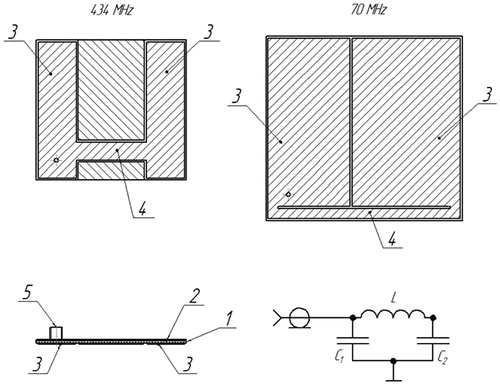
Theoretical and experimental investigations were performed to simulate and select the final design for the 70 MHz single applicator. The inductance is realised as a strip line connecting two edge coplanar capacitors as shown in (right view). The coplanar capacitance values and strip inductance had to be increased in order to get the contour resonance frequency in small sizes (92 × 98 mm) in the 70-MHz range. This was achieved by selecting 1.28-mm thick RO3010 series foiled material with a four times higher dielectric permeability of 10.2 (Rogers Corporation, Rogers, CT, USA).
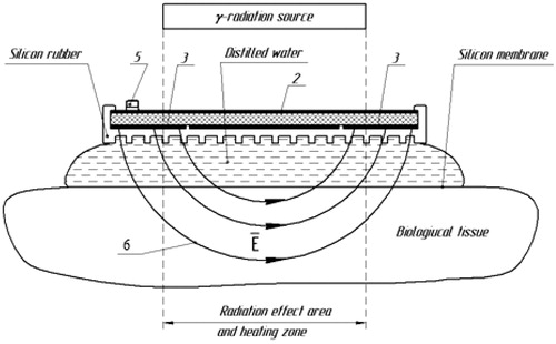
When exciting the circuit at the resonance frequency, an electric field () is generated between the plates (3) of the radiating conductor, the field lines (6) of the electric field close from one plate to the other plate through the layer of cooling water and the tissue underneath, causing tissue heating. The use of cooling water increases the heating depth by decreasing the tissue temperature in the most superficial tissue layer.
Figure 2. Schematic drawing of applicator antenna cross-section. Microstrip antenna consisting of dielectric substrate (1), ground conductor (2), plate (3), strip line (4), input coaxial connector (5), and resulting electric field lines (6).
Measurement of the electromagnetic field distribution generated by the applicator was performed using the set-up shown in . A 2.5-mm high-resistance measuring probe with a semiconductor detector (field sensor) is scanned through the radiation zone inside a liquid target equivalent phantom positioned underneath the applicator under test. This phantom contains 1% NaCl saline and measures 40 × 30 × 20 cm ().
Figure 3. Block scheme of measurements of distribution of a component of the EM field created by a microwave applicator in the liquid phantom with G4-76 A microwave generator (1), unidirectional coupler (2), M3-45 Wattmeter (3), Rem3.043.007 field sensor (4), arm holding the field sensor (5), movable strip (6), digital voltmeter (7), wall phantom (8), liquid target equivalent phantom (1% NaCl saline solution) (9), and applicator under study (10).
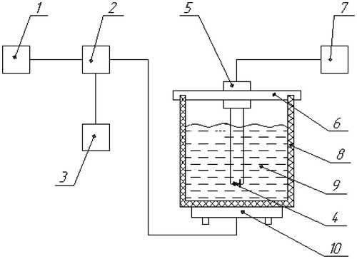
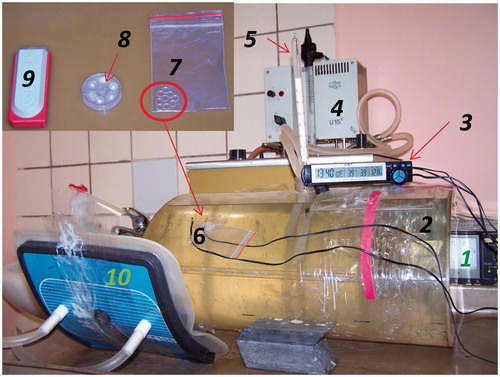
Figure 4. Experimental set-up for evaluation of the temperature increase at the surface of the phantom when TLDs are placed between bolus and phantom with stabiliser of power supplies (1), elliptical phantom (40 × 30 × 20 cm) with 1% NaCl solution (2), electronic thermometer (3), thermostat (4), mercury thermometer for measurement of the temperature of the phantom (5), thermocouples for measurement of the surface temperature of the phantom (6), flexible cassette with TLDs (7), MEPhI cassette (7 × 26 mm) with 5 TLDs (8), commercial cassette (60 × 24 × 12 mm) with three TLDs (9), and applicator (10).
The area of effective heating provided by the applicator is obtained by measuring the SAR distribution in the plane perpendicular to the applicator axis at 10 mm depth from the phantom surface. The applicator parameters thus obtained allow the defining of the volume in which the tissue is effectively heated. Measurements of VSWR and frequency characteristics of the applicators were performed using the standard set-up used for heating the phantom.
Applicator arrays
New types of applicators with new characteristics are created by combining multiple single applicators into an array, where each individual element requires connection to an RF-source with independent amplitude and phase control. In this way it is possible to design applicators with different apertures and the ability to modify the SAR distribution over the aperture as well as adapt to different geometrical shapes.
The following nomenclature was introduced to distinguish the different applicator modules:
CFMA−SRH-№A (434) – is a contact flexible microstrip applicator with simultaneous application of radiation and heating operating at 434 MHz,
CFMA−SRH-№A (70) – is a similar applicator, but operating at 70 MHz, and in both cases №А indicates the number of single applicators on one substrate.
HFSS version 12.0 (ANSYS, Canonsburg, PA) was used to simulate the antenna characteristics for different antenna arrays consisting of three, four, nine and twelve individual applicators, with a 1-cm thick water bolus containing distilled water and the liquid phantom.
Before tuning, the applicator antenna should have the resonance point at 434.5 MHz for the Teflon-foiled material; and at 71 MHz for the RO3010 series-foiled material. Next the inductance value was gradually increased to tune the antenna to the exact resonance frequency without changing the coplanar capacitances. This was achieved by step by step removal of the foiled layer from certain parts of the board by chemical etching to increase the strip length, and thus the inductance. In this way the resonance frequency gradually approached the point of resonance: either 433.92 MHz or 70 MHz.
As the wavelength at 70 MHz is more than six times larger than at 434 MHz, we had to increase the area of a single applicator to accommodate an operating frequency of 70 MHz, even when using a substrate material with a dielectric permeability of 10.2, four times higher than the dielectric permeability of Teflon of 2.5 used at 434 MHz. This four-fold increase in dielectric permeability results in a 50% reduction of the area needed.
SAR calculations were conducted for a single 70 MHz and 434 MHz applicator for each antenna location within the applicator array. The number of adjacent applicators was defined by their location within the structure of the multi-antenna applicator array. Based on this location the adjacent applicator at each side was either absent or inactive.
We conducted a radiation endurance test of both the 434 MHz and 70 MHz CFMA-SRH antennas to evaluate the number of patients who can be treated with one applicator with simultaneous hyperthermia and ionising radiation.
Monitoring the interaction with γ-radiation
Gamma-ray irradiation passes through the applicator and bolus in the SRH method. Earlier measurements of the radiation dose distribution in a phantom behind an earlier but similar version of the applicator showed that absorption was limited and that the structures within the applicator do not cause significant changes in the radiation dose distribution [Citation32]. Thus photons are scattered and absorbed by the applicator, but mainly by the cooling water flowing through the bolus. The latter is a challenge since there will be patient-specific differences in water bolus thickness due to the curved body surface.
The attenuation of the photon flux by the applicator was evaluated theoretically for 60Co and for photons with a wide range of primary energies. Attenuation was tested experimentally using a collimated beam of 60Co as cobalt irradiation has a negligible initial build-up effect in skin compared to other forms of irradiation and is therefore often used for superficial tumour lesions. The empty elliptical phantom with applicator was placed above the collimator on a moveable plastic platform. The dose rate measurement was carried out using a small Geiger counter in a perforated screen to improve the dose efficiency as a function of energy. Scanning was carried out with 1-cm steps along the long side at a distance of 5 cm from the edge of the applicator. The applicator has also been attached to the phantom to study the effect of non-uniformity due to curved surfaces. Measurements have shown that the distinction in photon dose attenuation along the length of bolus due to changes in water layer thickness reached a minimal value of 6% at an average water layer thickness of 1.27 cm. A dosimeter has to be placed between the bolus and the body of the patient to account for this bolus thickness-dependent attenuation.
The gamma-dosimeter must be transparent to high frequency electromagnetic radiation of the applicator, which means that it should not contain conductors. The presence of the dosimeter should not increase the local skin temperature by disrupting heat transfer between bolus and skin. The value measured by the dosimeter has to comply with the dose absorbed in water (or tissue) in a wide range of photon energies.
Thermoluminescence detectors (TLD) of lithium fluoride (Mg, Ti) dosimeters made by the Angarsk Electrolysis Chemical Complex [Citation33] were used for gamma radiation dose measurement. These TLDs are small single-crystal discs with a diameter of 4.5 mm and a thickness of 0.9 mm or 0.236 g/cm2.
TLDs of this type have some peaks of light emission in the 60–200 °C interval. An estimate of the fading was calculated for 50 °C and an exposure of ∼3 h. The loss glow is less than 0.01% for the used peak (200 °C). The loss of glow was shown not to exceed 10% for all peaks for 3 h exposure at 70 °C [Citation34]. Ivanov [Citation35] noted that fading did not exceed 5% for 48 h at 50 °C. Our experiments confirmed the glow loss is negligible for 2 h and 50 °C. The detectors were selected to have almost the same sensitivity; the spread was ∼5%. Several configurations of dose monitor blocks have been considered.
The influence of different cassettes including a flexible cassette with TLDs on the temperature recorded at the phantom surface [Citation36] was investigated using the set-up and cassettes shown in . The water temperature inside the phantom is controlled with a thermostat with a stability of about 0.5 °C to maintain a constant surface temperature.
Similar experiments have been carried out with participation of three volunteers. For practical reasons only the flexible cassette was used in these experiments. The applicator was mounted on the arm and thigh. The flexible cassette is designed as a double layer of polyethylene film with the detector between them. The ratio of the absorbed energy in the TLD to the dose in water (or soft tissue) of the photon energy can be taken into account for typical exposure conditions. Suppose the monodirectional stream of photons falls perpendicularly on the surface of the detector area S. Then, the absorbed energy w is equal to
(1)
with Ф the fluence of the photons; E the photon energy (MeV); S the area of the detector (cm2); µ, µen the attenuation coefficients and energy absorption (cm2/g); t the effective thickness of the detector (g/cm2).
Then, moving to the absorbed dose in water DH2O, we obtain
(2)
with M the mass of the TLD.
The results of calculations using Equation Equation2(2) are presented in .
Table 1. The ratio of the absorbed energy in LiF to the absorbed dose in water.
However, Equation Equation2(2) does not take the leakage of energy from the TLD and the flow of energy from the environment into account.
A Monte Carlo-based computer model was applied to calculate the absorbed energy in the cylindrically shaped detector with thickness 0.09 cm and diameter of 0.45 cm (LiF density of 2.635 g/cm3). In front of the detector is a 1.5 cm thick water layer and behind the detector is 30 cm of water. The main result of the calculation is the total absorbed energy per primary photon, which was determined as the difference between the sum of the energies of the secondary electrons formed by the photon and the total energy of the particles escaped from the detector.
The absorbed energy in water and TLD detector has been calculated in view of the contribution of scattered and reflected photons for 60Co using spectra devised by the Monte Carlo method [Citation37]. The discrepancy with respect to absorbed energy in air did not exceed 4%.
The accuracy of the calculations was verified experimentally.
The ratio of doses in LiF detectors and in water was calculated for high energy photon radiation, more precisely the bremsstrahlung spectrum which extends from tens of kilovolts to the energy of accelerated electrons.
Results
Single applicator
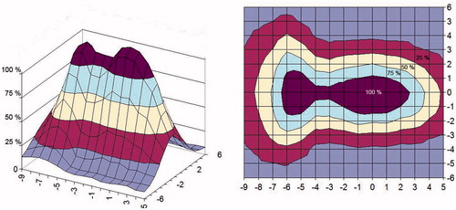
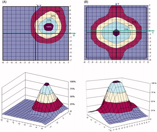
The SAR distribution measured in the phantom is shown in and for a 434 MHz and a 70 MHz applicator, respectively. To allow comparison, both are measured at a distance of 1 cm from the water bolus surface and parallel to the plane of the applicator aperture. The areas where SAR levels equal 25, 50 and 75% of maximum SAR are highlighted to evaluate the uniformity of the SAR distribution [Citation38].
Figure 5. The measured SAR distribution of a single 434 MHz applicator with cooling water bolus measured in the aperture plane in the phantom (1% NaCl saline solution) at 1 cm depth from the surface.
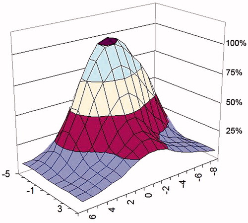
Figure 6. The measured SAR distribution for a single 70 MHz applicator with cooling water bolus obtained in the aperture plane at 1 cm depth from the surface of the phantom (1% NaCl saline solution).
Applicator arrays
Prototypes were manufactured of four types of 434 MHz multi antenna array applicators:
CFMA−SRH−4(434) array applicator with aperture size 140 × 150 mm, consisting of 2 × 2 applicators (single applicator size 70 × 75 mm),
CFMA−SRH−9(434) array applicator with aperture size 188 × 198 mm, consisting of 3 × 3 applicators (single applicator size 62 × 66 mm),
CFMA−SRH−12(434) array applicator with aperture size 197x285 mm, consisting of 3 × 4 applicators (single applicator size 65 × 71 mm),
CFMA−SRH−3(434) array applicator with aperture size 70 × 188 mm, consisting of 1 × 3 applicators (single applicator size 62 × 70 mm),
More samples of four types of applicators were manufactured. Prototypes of two of the four different 434 MHz applicators are shown in .
demonstrates the excellent agreement between the calculated and measured SAR distribution of the 2 × 2 434 MHz applicator (CFMA−SRH−4(434)) in the applicator aperture plane (in X-Y coordinates) in the phantom at 1 cm depth, respectively. The feeding was made from separate RF-sources, in this example with four active single applicators with identical phase and amplitude settings. The resulting constructive addition of EMF vectors from the four separate antennas yields a single continuous SAR maximum. shows the measured distribution for the four active single applicators with identical phase and amplitude settings in comparison to the distribution of just a single active applicator ().
Figure 7. The 2 × 2 434 MHz CFMA-SRH-4 (434) applicator with an aperture size of 140 × 150 mm, consisting of four applicators, each 70 × 75 mm (left), and the 3 × 4 434 MHz CFMA-SRH-12 (434) applicator with an aperture size of 197 × 285 mm, consisting of 12 applicators, each 65 × 71 mm (right).
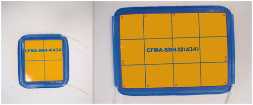
Figure 8. SAR distribution of the 2 × 2 434 MHz applicator (CFMA-SRH-4 (434)) in the applicator aperture plane at 1 cm depth in the 1% NaCl saline solution, all four single applicators active. Identical amplitude and phase were used for all four applicators: (A) simulated, (B) measured.
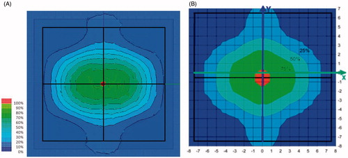
Figure 9. Measured SAR of the 2 × 2 434 MHz applicator (CFMA-SRH-4 (434)) in the applicator aperture plane at 1 cm depth in the phantom (1% NaCl saline solution). (A) Single active applicator, (B) all four applicators active. Identical amplitude and phase were used for all four applicators.
Prototypes were also manufactured of two types of 70 MHz applicators:
CFMA−SRH-4(70) array applicator with aperture size 188 × 198 mm, consisting of 2 × 2 applicators (single applicator size 92 × 98 mm),
CFMA−SRH-6(70) array applicator with aperture size 197 × 285 mm, consisting of 2 × 3 applicators (single applicator size 93 × 97 mm).
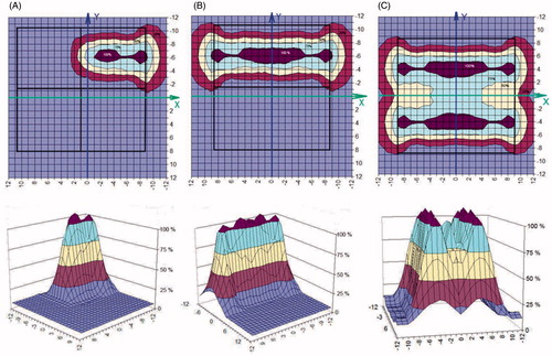
shows the measured SAR distribution of one, two and four active single applicators of the 2 × 2 70 MHz applicator CFMA−SRH-4(70) in the applicator aperture plane at 1 cm depth from the surface of the phantom.
Figure 10. Measured SAR of a single, double or quadruple active applicator of the 2 × 2 70 MHz applicator (CFMA-SRH-4 (70)) in the applicator aperture plane at 1 cm depth in the phantom (1% NaCl saline solution. Identical amplitude and phase were used for all active applicators: (A) single active applicator, (B) two active applicators, (C) all four applicators active.
The radiation endurance tests showed that 36700 Gy was the maximum permissible dose for the RO3010 series antenna substrate. Hence, one CFMA−SRH-№A(70) applicator can be used in up to 7340 5 Gy SRH procedures, which is equivalent to 610 patients if each patient is treated with 60 Gy in total. Similar tests showed that one CFMA−SRH-№A(434) applicator can endure a maximum of 21600 Gy, this is equivalent to treatment of 360 patients if each patient is treated with 60 Gy in total with simultaneous hyperthermia and ionising radiation. The substrate of Rogers material RO3010 thus appears to be twice as resistant to ionising radiation than the FAF-4D Teflon substrate.
Monitoring the interaction with γ-radiation
The applicators can be supplemented with self-sufficient TLD dosimeters to monitor differences in attenuation of the photon flux in the water bolus due to the variability of the bolus thickness. Measurement of the influence of the presence of the different TLD cassettes yielded the following temperature increase on the phantom surface:
Cluster of nine bare TLDs: 1–2 °C,
Flexible film cassette with TLDs: 1–3 °C,
MEPhI Cassette: 6–7 °C,
Commercial specimen DTG-4: 7–8 °C.
Measurements on the skin of three volunteers have confirmed that placement of the flexible cassettes increases the skin temperature up to 1–3 °C, a value much lower than for conventional options (the MEPhI and DTG-4 cassettes).
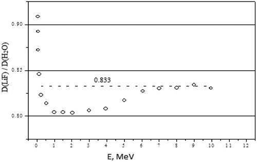
The ratio of absorbed energy in the TLD lying between phantom and applicator and the absorbed dose in the water at that location has been determined for photons with primary energies from 30 keV to 30 MeV to assess its dependence on photon energy. Calculation results indicate that the dose dependence on the photon energy in water and in the LiF detectors is almost proportional. The ratio of the absorbed dose in LiF and in the water stabilises at 0.833 (±3%) when the photon energy is more than 60 keV, as shown in . Applicators attenuate the flux of high energy photons with about 3–6% and with 10% for 60Co.
Figure 11. Dependence of the relation of the absorbed doses in water and in LiF is conditioned by energy of photons (a thin beam – a wide source); 0.833 – average value of the relations of doses.
Interesting results emerged from the calculated ratio of the dose in LiF detectors and in water for the bremsstrahlung spectrum. Calculations yielded a ratio of doses in water and in LiF in the adopted geometry of 0.83, 0.81, 0.82 and 0.82 for 6, 10, 20 and 30 MV, respectively. Thus, these results show that LiF detectors without compensating filters (i.e. the Teflon layer of the MEPhI or the DTG-4 cassette) can be applied for measurement of doses in water or in soft tissue in the range of photon energies used in radiotherapy. Consequently a flexible cassette is preferable as it disturbs the temperature less than other cassettes; the measured quantity is proportional to dose in water at the location between bolus and body.
Discussion
A series of contact flexible microstrip applicators (CFMA-SRH) have been developed, operating at 434 MHz and 70 MHz with different aperture sizes and suitable for simultaneous action of radiation and heat by allowing effective irradiation of a tumour by ionising radiation through the applicator. The characteristics of the heating areas generated by EM field radiated by both single applicators and arrays were investigated, and demonstrated that spatial SAR steering is possible with both the 434 MHz and 70 MHz applicators. The 25% SAR contour can be seen to cover nearly all of the aperture for one, two or more active elements for the 2 × 2 70 MHz CFMA-SRH-4(70) applicator in and for a single active applicator in . This is not the case for the all four active applicators of the 2 × 2 434 MHz CFMA-SRH-4(434), probably due to the coherent mode used in .
Excessive doses of high energy ionising radiation result in brittleness of the RO3010 and FAF-4D substrate at forced bending of the applicators. Endurance studies demonstrated that the 434 MHz applicators can endure a radiation dose up to 21.6 kGy without a loss of functionality. Thus one 434 MHz applicator can be used to treat up to 360 patients (about 4300 SRH procedures). The 70 MHz applicators can endure a radiation dose up to 36 kGy; one applicator can be used to treat up to 610 patients (about 7340 SRH procedures). These are acceptable numbers, particularly in view of the fact that frequent and repeated bending of the applicator for large numbers of patients is also likely to cause wear. Also note that many materials used in clinical care are disposable and used only once.
The 60Co irradiation used in our experiments displays a negligible initial build-up effect in skin. The presence of a hyperthermia applicator with water bolus on the skin acts similarly, as the bolus that is often used in radiotherapy with high energy photons to compensate for the initial build-up effect in skin when targeting superficial tumour lesions. Thus it might be logical to combine hyperthermia with 4 MV or 6 MV photons during simultaneous hyperthermia and radiotherapy for superficial lesions as 4–6 MV has a build-up region similar in size to the bolus of our applicator.
Photons are mainly scattered and absorbed by the cooling water in the water bolus, differences in the water bolus thickness thus have a direct impact on the dose distribution. A self-sustaining dosimeter block was developed to monitor this phenomenon, consisting of a low-cost flexible film cassette for TLDs. A small drawback is that its presence increased the local temperature, but less than 3 °C. Other options to assess deviations in the dose distribution could include the use of treatment planning based on imaging of the bolus thickness prior to every treatment session.
The dose heterogeneity resulting from the presence of the applicator and water bolus is substantial and close to the maximum accepted in clinical radiotherapy, but note that in the present clinical practice hyperthermia is not given with every radiotherapy fraction, but just once a week. Non-uniform doses during combined treatment would then be compensated by the better controlled dose during the much larger number of radiotherapy-only sessions. One combined session followed by four radiotherapy-only sessions per week would effectively reduce heterogeneity to ∼1–2%, which is considered acceptable in radiotherapy. This would also result in a prolonged life-time of the applicator.
In the TLD located between phantom and applicator, the ratios of absorbed energy to dose in water in this point were shown to remain equal, 0.833 ± 3% for energy intervals from 60 up 10,000 keV.
Conclusion
Simultaneous action of radiation and local hyperthermia is associated with significantly improved clinical effectiveness and is technically realisable using newly developed radiation-resistant microwave applicators. Important features are flexibility, transparency to ionising radiation, optional real-time radiation dose measurement, the option of using an array of up to 12 independent elements and the availability of both 434 MHz and 70 MHz applicators for superficial and for deeper-seated tumours, respectively.
The next step is the last test of delivering both modalities simultaneously, followed by assessing clinical feasibility in a phase I trial of simultaneous irradiation and hyperthermia using these new applicators.
Acknowledgements
The authors thank V.P. Legonkih for assistance in carrying out the simulations.
Declaration of interest
This research was performed within the framework of International Science and Technology Center (ISTC) project 3996 with financial support of the EU. Dr Mazokhin is employed by Istok, the other authors report no conflicts of interest. The authors alone are responsible for the content and writing of the paper.
References
- Overgaard J. The current and potential role of HT in radiotherapy. Int J Radiat Oncol Biol Phys 1989;16:538–49
- Field SB, Hand JW, eds. An Introduction to the Practical Aspects of Clinical Hyperthermia. London & New York: Taylor & Francis, 1990
- Vernon CC, Hand JW, Field SB, Machin D, Whaley JB, van der Zee J, et al. Radiotherapy with and without hyperthermia in the treatment of superficial localized breast cancer: Results from five randomized control trials. Int J Radiat Oncol Biol Phys 1996;35:731–44
- Horsman MR, Overgaard J. Can mild hyperthermia improve tumor oxygenation? Int J Hyperthermia 1997;13:141–8
- Krawczyk PM, Eppink B, Essers J, Stap J, Rodermond H, Odijk H, et al. Mild hyperthermia inhibits homologous recombination, induces BRCA2 degradation, and sensitizes cancer cells to poly (ADP-ribose) polymerase-1 inhibition. Proc Natl Acad Sci USA 2011;108:9851–6
- Eppink B, Krawczyk PM, Stap J, Kanaar R. Hyperthermia-induced DNA repair deficiency suggests novel therapeutic anti-cancer strategies. Int J Hyperthermia 2012;28:509–17
- Zagar TM, Vujaskovic Z, Formenti S, Rugo H, Muggia F, O’Connor B, et al. Two phase I dose-escalation/pharmacokinetics studies of low temperature liposomal doxorubicin (LTLD) and mild local hyperthermia in heavily pretreated patients with local regionally recurrent breast cancer. Int J Hyperthermia 2014;30:285–94
- Kampinga HH, Dynlacht JR, Dikomey E. Mechanism of radiosensitization by hyperthermia (≥ 43 °C) as derived from studies with DNA repair defective mutant cell lines. Int J Hyperthermia 2004;20:131–9
- Kampinga HH. Cell biological effects of hyperthermia alone or combined with radiation or drugs: A short introduction to newcomers in the field. Int J Hyperthermia 2006;22:191–6
- Sherar M, Liu FF, Pintilie M, Levin W, Hunt J, Hill R, et al. Relationship between thermal dose and outcome in thermoradiotherapy treatments for superficial recurrences of breast cancer: Data from a phase III trial. Int J Radiat Oncol Biol Phys 1997;39:371–80
- Overgaard J, Gonzalez Gonzalez D, Hulshof MC, Arcangeli G, Dahl O, Mella O, et al. Randomised trial of hyperthermia as adjuvant to radiotherapy for recurrent or metastatic malignant melanoma. European Society for Hyperthermic Oncology. Lancet 1995;345:540–3
- Valdagni R, Amichetti M, Pani G. Radical radiation alone versus radical radiation plus microwave hyperthermia for N3 (TNM-UICC) neck nodes: A prospective randomized clinical trial. Int J Radiat Oncol Biol Phys 1988;15:13–24
- Jones EL, Oleson JR, Prosnitz LR, Samulski TV, Vujaskovic Z, Yu D, et al. Randomized trial of hyperthermia and radiation for superficial tumors. J Clin Oncol 2005;23:3079–85
- Van der Zee J, González González D, van Rhoon GC, van Dijk JD, van Putten WL, Hart AA. Comparison of radiotherapy alone with radiotherapy plus hyperthermia in locally advanced pelvic tumours: A prospective, randomised, multicentre trial. Dutch Deep Hyperthermia Group. Lancet 2000;355:1119–25
- Horsman MR, Overgaard J. Hyperthermia: A potent enhancer of radiotherapy. Clin Oncol (R Coll Radiol) 2007;19:418–26
- Diederich CJ, Stauffer PR, Khalil JS, Sneed PK, Phillips TL. Direct-coupled interstitial ultrasound applicators for simultaneous thermobrachytherapy: A feasibility study. Int J Hyperthermia 1996;12:401–19
- Moros EG, Straube WL, Klein EE, Maurath J, Myerson RJ. Clinical system for simultaneous external superficial microwave hyperthermia and cobalt-60 radiation. Int J Hyperthermia 1995;11:11–12
- Straube WL, Moros EG, Low DA, Klein EE, Willcut VM, Myerson RJ. An ultrasound system for simultaneous US hyperthermia and photon beam irradiation. Int J Radiat Oncol Biol Phys 1996;36:1189–200
- Moros EG, Peñagaricano J, Novàk P, Straube WL, Myerson RJ. Present and future technology for simultaneous superficial thermoradiotherapy of breast cancer. Int J Hyperthermia 2010;26:699–709
- Juang T, Stauffer PR, Neuman DG, Schlorff JL. Multilayer conformal applicator for microwave heating and brachytherapy treatment of superficial tissue disease. Int J Hyperthermia 2006;22:527–44
- Diederich CJ, Stauffer PR. Pre-clinical evaluation of a microwave planar array applicator for superficial hyperthermia. Int J Hyperthermia 1993;9:227–46
- Stauffer PR, Maccarini P, Arunachalam K, Craciunescu O, Diederich C, Juang T, et al. Conformal microwave array (CMA) applicators for hyperthermia of diffuse chest wall recurrence. Int J Hyperthermia 2010;26:686–98
- Montes H, Hynynen K. A system for the simultaneous delivery of intraoperative radiation and ultrasound hyperthermia. Int J Hyperthermia 1995;11:109–19
- Novák P, Moros EG, Straube WL, Myerson RJ. SURLAS: A new clinical grade ultrasound system for sequential or concomitant thermoradiotherapy of superficial tumors: Applicator description. Med Phys 2005;32:230–40
- Peñagarícano JA, Moros E, Novák P, Yan Y, Corry P. Feasibility of concurrent treatment with the scanning ultrasound reflector linear array system (SURLAS) and the helical tomotherapy system. Int J Hyperthermia 2008;24:377–88
- Gelvich EA, Kolmakov DN, Kudryavtsev YS, Mazokhin VN. Contact flexible microstrip applicators (CFMA) for superficial and deep hyperthermia. COMAC-BME Hyperthermia Bulletin 1992;10:66–72
- Gelvich EА, Mazokhin VN, Troshin II. Contact microstrip applicators for superficial, deep and whole-body hyperthermia. Microwave in Medicine 1993, 2nd International Scientific Meeting, 11–14 October, Rome, 1993, pp. 71–4
- Gelvich EA, Mazokhin VN. Contact flexible microstrip applicators (CFMA) in a range from microwaves up to short waves. IEEE Trans Biomed Eng 2002;49:1015–23
- Mazokhin VN, Gelvich EA. Miniature microwave EM applicators for heating malignant tumors of rodents. 24th Annual Meeting ESHO-2007, Prague, Book of Abstracts, 2007, pp. 96–7
- Mazokhin VN, Gelvich EA. CFMA-like applicators allowing heating of the tumor simultaneously with its external radiation. 23rd Annual Meeting of the ESHO, Berlin, Book of Abstracts, 2006, pp. 31–2
- Neuman DG, Stauffer PR, Jacobsen S, Rossetto F. SAR pattern perturbations from resonance effects in water bolus layers used with superficial microwave hyperthermia applicators. Int J Hyperthermia 2002;18:180–93
- Gorlachev GE, Klimanov VA. 3D dose planning system for simultaneous treatment by UHF-hyperthermia and distant beam therapy. 23rd Annual Meeting of the European Society for Hyperthermic Oncology (ESHO 2006), Berlin, Charite, 24–27 May 2006, p. 36
- Gelvich EA, Klimanov VA, Kramer-Ageev EA, Mazokhin VN. Computational evaluation of changes in ionizing radiation dose distribution in tissues caused by EM applicators, when external radiation and hyperthermia act simultaneously. Int J Hyperthermia 2006;22:343–52
- Shani G. Radiation Dosimetry Instrumtation and Methods. Boca Raton, FL: CRC Press, 1991, pp. 63–109
- Ivanov VI. Course of Dosimetry (in Russian). Moscow: Atomizdat, 1988
- Klimanov VA, Kramer-Ageev EA, Mogilenets NN, Smirnov VV, Zvantsev AA. Dosimetry of photon radiation in simultaneous action hyperthermia and irradiation. 27th ESHO Annual Meeting, 26–28 May 2011 Book of Abstracts, Aarhus, 2011, p. 47
- Mora GM, Moioa A, Rogers DWO. Monte Carlo Simulation of Typical 60Co Therapy Source. Med Phys 1999;26:2494–501
- Gelvich EA, Mazokhin VN, Troshin II. An attempt at quantitative specification of SAR distribution homogeneity. Int J Hyperthermia 1996;12:431–6