
Abstract
Purpose: This paper compares the results obtained with numerical simulations and ex vivo experiments involving a dual applicator microwave thermal ablation system operating at a 2.45 GHz frequency, both in synchronous and asynchronous modes. Our purpose was to demonstrate that at this frequency an asynchronous or switched-mode system performs essentially as well as the synchronous one, in spite of the prevailing belief that coherence would assure better thermal (TH) synergy. Numerical analysis: The calculations of temperature fields were based on the Pennes bioheat equation, taking into account the effects of blood perfusion by means of a full-wave 3D simulator that allows numerical electromagnetic (EM) and TH analyses. Materials and methods: Experiments were done using a 100 W microwave (MW) power generator and a fast switched-mode sequential ‘active’ power splitter. By adding a further passive power splitter we arranged a test bed for an accurate experimental comparison of synchronous versus switched-mode TH ablations. Results: The experimental ablation zones produced by a dual applicator array on ex vivo swine tissue corresponded well with the simulated ones, confirming that the simplifications assumed in the full-wave analysis were compatible with the aim of our work. Conclusions: Numerical simulations and experiments show that at a 2.45 GHz industrial, scientific and medical (ISM) frequency, synchronous, asynchronous and switched-mode multi-probe systems are substantially equivalent in terms of ablative performance. Moreover, the switched-mode solution offers simpler operation along with lesser sensitivity to the placement of applicators in the tissue.
Introduction
In cancer treatment, open surgery and chemotherapy are still physicians’ first choices. For some patients, however, removal of tumours with open surgery is not possible or involves too high a risk due to the poor condition of the patient. Therefore, surgical success rates largely depend on the type of malignancy treated and on disease progression [Citation1]. Minimally invasive surgery or percutaneous interventions may, in this case, be adequate to increase safety, reduce trauma and shorten operative time [Citation2–4].
Microwave thermal ablation (MWA) is a relatively new technology in continuous development, and one which offers some advantages when compared to the radiofrequency ablation (RFA) technology which currently represents the prevailing clinical focal therapy [Citation5–7]. MWA can generate higher temperatures in less time since tissue charring does not hinder the radiation of microwaves (MWs) and it is less susceptible to the heat-sink effect of peritumoural vessels [Citation8,Citation9]. For these reasons, MWs, given their minimally invasive effect, are fertile ground for innovation through new systems and technological developments.
The power that the coaxial structure of a MW applicator can safely handle is proportional to its external diameter; therefore, very small diameter applicators can handle proportionally smaller powers [Citation10]. However, this physical limitation can be overcome by cooling the applicator shaft [Citation11–16] or by combining more than one antenna into an array of applicators in order to increase coagulation volume [Citation17–21]. Still, due to the high losses of the internal coaxial feeding line, a small-diameter shaft cooled antenna has an intrinsically low radiating efficiency that rapidly falls with the decrease in its external diameter.
As a matter of principle, a single applicator appears unable to uniformly and efficiently heat a large volume of tissue because the emitted radiation is subjected to very strong attenuation, due to the intrinsic, high propagation losses within the biological tissue.
Recent studies [Citation17–19] show a fundamental advantage in using multiple antennas: power distribution in a multiple-probe system is more effective, even when compared to that of a single antenna that provides the same amount of energy. Indeed, by means of the thermal synergy effect, the heat produced simultaneously by an array of radiating sources can create ablation areas that are larger than what we might expect by simply adding their heating patterns [Citation19]. This ability to perform multiple ablations simultaneously may allow for the treatment of larger tumours with concurrent overlapping thermal (TH) lesions [Citation18] or the ablation of several anatomically separate tumour lesions all at once. Furthermore, properly assembled linear or conformal arrays of applicators can be used as surgical resection devices to reduce blood loss and assist in tissue coagulation during intraoperative and laparoscopic surgical procedures [Citation22–24].
Multi-probe ablations reduce the need for repeat treatments, decrease the number of inadequate treatments of larger tumours, and increase the speed of therapy, thereby decreasing the complication rate [Citation25].
A multi-applicator thermoablative system can be conceived and constructed following different technical approaches, essentially regarding the feeding modality of the applicators’ array. Our study is devoted to comparing the performances of these different feeding modes.
The paper is organised as follows: the second section discusses the different feeding techniques, the third section presents numerical comparisons among synchronous, asynchronous and FSS feeding modes, while the fourth section presents the results of ex vivo experiments. The fifth and sixth sections summarise the main conclusions.
Feeding modalities of a multi-probe array
From a systems point of view, an array of antennas can be synchronously or asynchronously fed using multiple single port MW generators or a single multiport generator. In the synchronous mode the array is fed by employing coherent power sources. Therefore the relative phase between the antennas can be used to effectively add or shape the electric field distributions in order to increase either gain or focus, or to make complex variations [Citation26]. In asynchronous operation non-coherent sources are employed so that the active interference among the fields can be modelled as a stochastic process. It is worth noting that an equivalent incoherent feeding can also be obtained by sequentially switching the antennas of the array depending on a common power source.
With regard to the feeding modality, there is a common belief that heating at the focusing point of an N-element circular array can be increased by N times if the array itself is asynchronously fed, while it can be increased by N2 times if synchronously fed [Citation17,Citation27]. Actually, this assumption is questionable since it seems rigorously true only if we refer to the electric fields in the ‘far-field’ zone (df >> λ, where df is the far-field distance) and in the context of an ideal unrealistic tissue having zero thermal conductivity. In a real, perfused biological tissue, the heat diffusion phenomenon plays a fundamental role in smoothing the temperature behaviour near the focusing points, such that the claimed advantages of synchronous versus asynchronous feeding are substantially lost.
Nevertheless, it has been proven [Citation6,Citation26,Citation28] that an array of N applicators presents optimal performance when operating synchronously at the 915 MHz frequency, assuming that the distance between two contiguous applicators does not exceed 22 mm, which corresponds to a half wavelength in liver tissue.
The simplest way to implement a synchronous or asynchronous MW N-needle ablative system consists in the simultaneous use of N power generators, where each generator feeds a corresponding applicator of the array.
However, this straightforward solution is certainly not optimal from an engineering point of view because solid-state MW power generators are very expensive and need to be phase-locked to a stable reference frequency for the synchronous operation.
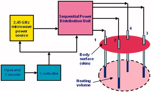
The use of multiple generators can be avoided by employing a single generator and a passive power splitter, as shown in .
Figure 1. Block diagram of a single generator, multi-output MW thermo-ablative system.
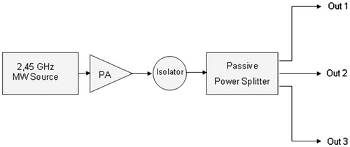
It should be noted that the use of classical passive power dividers or splitters naturally leads to a synchronous system solution that reduces system complexity and costs, but suffers from poor flexibility because the total available power at the generator output port (Ptot) is equally split among N ports; therefore, when a single applicator is used, the maximum allowable power is only Ptot/N.
To overcome this problem and to increase system flexibility, power distribution among N applicators can be accomplished using the switched-mode approach, where the N applicators of the array are fed sequentially in time [Citation29]. This leads to a simple and highly flexible asynchronous solution, where the switching frequency must be kept high enough to prevent a localised temperature drop during the applicator’s off-time, thus enabling the highest allowable TH synergy.
To efficiently emulate an ideal single-generator asynchronous mode we propose an approach called ‘fast sequential switching’ (FSS) which provides many advantages in terms of reduction of system complexity, robustness, and operational flexibility without at the same time suffering any significant power losses and maintaining a high overall energy efficiency. The FSS concept is based on the fact that the thermal time constant τ of biological tissues is relatively high (in the order of several seconds). Therefore if MW power is applied in a periodic pulsed mode with very short pulse periods ranging from 0.5 to 2 s, the tissue temperature tends to be related to the average applied power, whose value is determined by the on/off duty cycle.
Numerical comparison of synchronous versus asynchronous feeding
Our study is not devoted to improving the analysis model to better match the real dynamic thermoablative process, but rather to comparing different multi-applicator feeding technologies in terms of their overall performance at the 2.45 GHz frequency, which is that specified in Europe for industrial, scientific and medical (ISM) MW applications.
When simulating a multi-applicator thermoablative process, the analysis domain is even more extended than that of a single applicator, for which an expanded model could be applied to obtain more realistic results without an excessive numerical burden [Citation30]. Therefore, a full 3D simulation is generally needed for multi-applicator numerical analysis, because the domain is not axisymmetric and its dimensionality cannot be reduced.
Numerical simulations have been carried out by employing CST MICROWAVE STUDIO® 3D simulation software (https://www.cst.com, Darmstadt, Germany), which is a rigorous full-wave 3D tool capable of performing both EM and TH analyses. CST’s EM solver is based on the finite integration technique (FIT), a consistent discretisation scheme for Maxwell’s equations in their integral form.
The heating process is modelled via the Pennes bioheat equation which includes blood perfusion phenomena [Citation5,Citation31,Citation32].
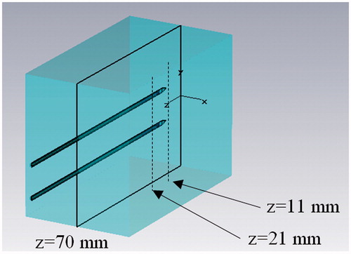
The heat transfer analysis in the region near the MW antennas is a critical factor that affects the entire temperature field during the MWA of the tissue. It is challenging to realistically predict the evolution of the tissue temperature distribution [Citation33] because the EM and TH properties of the tumour change with the increase in temperature. Furthermore, vaporisation phenomena occur [Citation34,Citation35] that are associated with tissue deformation [Citation36]. To reduce the numerical burden, we consider the simplest case of a pair of MW applicators [Citation37] immersed in a time and space invariant homogeneous tissue, as depicted in which shows the 3D analysis domain. Furthermore, the analysis is made using uncoupled EM and TH equations, such that the variability of the tissue parameters with temperature and time is not taken into account as described in [Citation38].
Figure 2. Numerical analysis domain (dimensions 120 × 60 × 60 mm). EM and TH boundary conditions are applied on all faces of the domain.
Perfectly matched layer (PML) boundary conditions are applied at the border of the analysis domain as shown in , and an automatic steady-state energy criterion is employed to end the simulation. In the TH simulations, boundary conditions are defined by enforcing the continuity of the heat flow perpendicular to the surface of the domain.
It should be noted that the coherence and the generality of the comparison are not compromised if we use a simplified model to reduce simulation time, given that the model approximations equally affect both synchronous and asynchronous feeding. Moreover, all of the above a priori simplifications have been validated by an a posteriori verification carried out by matching numerical and experimental results that were shown to be satisfactory for the purpose of this study.
The reference tissue used for the simulations is muscle, whose parameters are listed in [Citation39]; this type of tissue was chosen in view of the experimental comparisons that can be made with swine loin for its better homogeneity.
Table 1. Physical properties of muscle tissue at 2.45 GHz frequency and 37°C temperature.
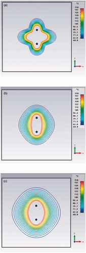
Since transient TH simulations are very time-consuming, a preliminary test comparing transient versus steady-state simulations was carried out. compares high energy pulsed (a), 6-min transient (b) and steady-state (c) simulations in the synchronous case. Note the similarity of the (b) and (c) behaviours due to the heat diffusion in the tissue; from this derives the possibility of using stationary TH analysis for the comparison, provided that the treatment time is not too short and that the total input power is the same.
Figure 3. Preliminary simulations comparing high energy pulsed (10 kJ, 1 s) (a), 6 min transient (b) and steady-state (c) power density distributions in the xy plane (z = 21 mm) for a dual applicator array operating at 2.45 GHz frequency.
For a detailed synchronous versus asynchronous comparison, we examined the behaviour of power density and temperature distributions for a pair of parallel applicators immersed in the reference tissue at distances of 12 mm and 20 mm, both of which are greater than the half wavelength in the tissue. Values smaller than the half wavelength, which are not of practical interest, were not considered.
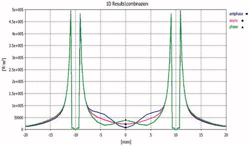
, and show the most significant simulation results in terms of power densities and temperature behaviours for three different feeding modes: in phase synchronous (green lines, ▴), out of phase synchronous (blue lines, ▪), and Q3 asynchronous (red lines, •).
Figure 4. Power density distribution in the xy plane (x = 0, z = 21 mm) using a pair of applicators at D = 12 mm, Pref = 1 W: in-hase feeding (green line), out-of-phase feeding (blue line), asynchronous feeding (red line).
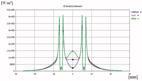
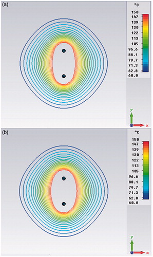
Figure 5. Temperature distribution in the xy plane (x = 0, z = 21 mm) (a), in the yz plane (y = 0, z = 21 mm) (b) and in the xz plane (x = 0, y = 0) (c), produced by a pair of applicators at D = 12 mm and with Ptot = 40 W: in-phase feeding (green line), out-of-phase feeding (blue line), asynchronous feeding (red line). In (a), the black dashed line refers to a single applicator with the same input power.
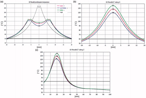
Figure 6. Power density distribution in the xy plane (x = 0, z = 21 mm) using a pair of applicators at D = 20 mm, Ptot = 20 W: in-phase feeding (green line), out-of-phase feeding (blue line), asynchronous feeding (red line).
The asynchronous feeding modality has been modelled by averaging a set of 3D simulated power densities which have pseudo-random inter-element phases or, more simply, uniformly distributed phases between 0 and 360 degrees. The resulting averaged power density distribution is then employed to calculate TH behaviour in the full 3D domain.
Results of the power density comparisons in the xy plane for an inter-element spacing of D = 12 mm are reported in . As expected, the in-phase synchronous feeding produces focusing in the centre of the array while out-of-phase feeding produces defocusing. This effect is confirmed by the temperature distribution shown in . Nevertheless, when changing from in-phase to out-of-phase feeding, the temperature drop is not so marked as that of the power density behaviour because of the heat diffusion phenomena. From the same figure we can also infer that a pair of applicators actually creates larger ablation zones and lower temperature gradients than a single applicator put at the centre of the array and fed with the same input power, as was to be expected.
The temperature distributions in the xy, yz and xz planes that are shown in can be used to calculate the ablation volume within the 60°C isotherm by using the formula V = 4/3 (π a b c), where a, b, c are the semi-axes of the ablation ellipsoid [Citation40]. Passing from the synchronous to the asynchronous case, we observe a reduction in the ablation volume of less than 10%. It can also be noted that asynchronous TH behaviours are in any case bounded between the in-phase and out-of-phase synchronous ones, as was expected.
If the distance between the two applicators is increased to D = 20 mm, as seen in , we can observe a minimum power density in y = 0 for the out-of-phase feeding but also an increase at y = ± 4.5 mm, corresponding to ± λ/4 in the muscle tissue. This is because near-field components radiated by the two applicators are additive in these points.
Complementary behaviour is observed for in-phase feeding, while asynchronous feeding appears more regular because phase incoherence destroys stationarity due to the interferences between near-fields. This smoothed behaviour is conserved when varying inter-applicator distance.
Temperature behaviours for D = 20 mm are not reported as they were very similar to those obtained for D = 12 mm and the reduction in ablation volume passing from the synchronous to the asynchronous feeding is in any case negligible. We can conclude that the expected advantage of the synchronous feeding tends to disappear when the inter-applicator distance is increased above half the tissue wavelength. This is why the synchronous solution works better at 915 MHz in liver tissue (λ/2 = 22 mm) than at 2450 MHz (λ/2 = 8.8 mm).
Additional numerical simulations have been carried out to prove the equivalence of synchronous, asynchronous and FSS systems for a pair of applicators placed at distance D = 12 mm. shows the FSS-mode power density distributions during the on/off cycle, while shows the comparison between synchronous and FSS modes. It should be noted that was obtained by adding by virtue of the superposition principle. Since we obtained the same behaviour for the asynchronous feeding, we can definitively assert the equivalence between the FSS and asynchronous modes, which could however also be deduced from intuitive physical considerations.
Figure 7. Power density distribution in the xy plane (z = 21 mm) of a dual applicator array operating in FSS mode during the first semi-period (a), and during the second semi-period (b).
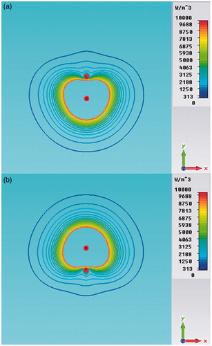
Figure 8. Power density distributions in the xy plane (z = 21 mm) of a dual applicator array operating in FSS mode (a) and in synchronous mode (b).
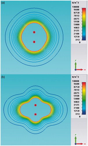
By comparing we can also observe that the FSS mode produces a more uniform power density distribution than the synchronous one, where stationary near-field interferences are present. However, due to the heat diffusion phenomenon, these differences become imperceptible in the iso-contour graphs of the steady-state TH distributions, as shown in .
Figure 9. Temperature distribution in the xy plane (z = 21 mm) of a dual applicator array operating in FSS mode (a) and in synchronous mode (b).
Results of ex vivo trials
Our experimental trials were carried out employing a prototype of the FSS-mode asynchronous system designated as Thermal Ablation Treatments for Oncology (TATO), and developed under a collaborative academia–industry effort [Citation37,Citation41,Citation42]. The TATO system, whose block diagram is shown in , performs as an ideal asynchronous system if the sequential switching operation is fast enough.
Figure 10. Block diagram of the asynchronous switched-mode TATO system.
Specifically, the ex vivo trials were devoted to experimentally validating the numerical comparison between synchronous and FSS feeding modes.
In order to obtain a reliable experimental comparison, a simple test bed could not be easily arranged, because we would have had to have used a pair of synchronous and FSS (asynchronous) ablation systems operating simultaneously under a unique common controller and employing identical applicators. Fortunately, however, a very simple and trustworthy test bed could be implemented by taking advantage of TATO’s operational flexibility.
illustrate how the experiment was performed using the TATO system with the addition of only a passive 3-dB Wilkinson power splitter.
Figure 11. The test bed used for the synchronous versus FSS (asynchronous) feeding comparison. Block diagram (a) and laboratory arrangement (b).
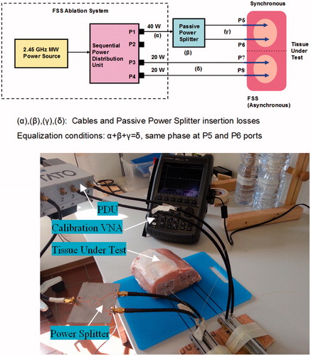
To the authors’ knowledge, this is the first testing system developed which allows the comparison of synchronous versus asynchronous modes with high precision and repeatability.
In order to achieve the best comparison accuracy, the electrical lengths and insertion losses of the cables connecting the sequential PDU to the four applicators have been equalised. This equalisation was achieved by adjusting the length of each physical path (P1–P5, P1–P6, P3–P7, P4–P8) by means of a vector network analyser (VNA).
The ablations trials were performed using pieces of fresh swine loin selected for the best homogeneity. During the transport to the lab, all tissues were maintained at a temperature of ∼15°C, which was slowly increased to ∼30°C before starting the experiments. Initial temperature uniformity of the loin piece was preliminarily tested before inserting the four 17-gauge coaxial applicators [Citation37] employed for the double simultaneous ablation process. The input reflection coefficient Г of each applicator was then measured in order to assure an in situ matching better than −15 dB.
Each applicator received the same net input power by virtue of the aforementioned accurate calibration procedure. Moreover, the two synchronous applicators were fed in phase by means of the Wilkinson 3-dB power divider. The ablation time was set at 10 min in all the experiments so as to better match the steady-state numerical simulations. Furthermore, the applicator cooling system was not enabled in order to avoid the appearance of various phenomena that could mask the real heat transfer within the tissue and distort the true final ablation zone observed.
For statistical confidence purposes, the experiment was repeated many (10) times, using different pieces of tissue and employing increasing inter-applicator separation ranging from 12 to 20 mm. At the end of each ablation process the input matching of the four applicators used was tested again; trials where one or more of the applicators presented an end ablation Г worse than −10 dB were disregarded.
shows the experimental results obtained with a separation of 15 mm that proved to be optimal for obtaining a more circular ablation in the transverse cut.
Figure 12. Comparison of TH ablation between synchronous and FSS (asynchronous) feeding modalities: (a) longitudinal cut, (b) transverse cut.
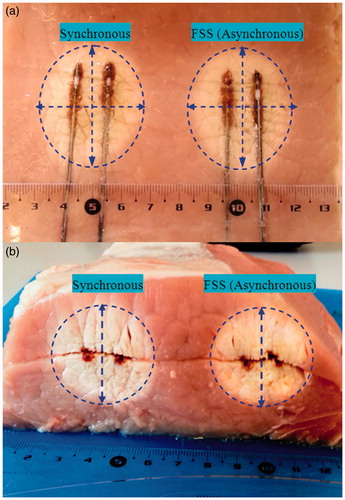
In this case the major axis diameter was 52 mm for synchronous configuration and 51 mm for FSS configuration. Minor axis diameter was 31.5 mm for synchronous configuration and 32 mm for FSS.
As far as the comparison is concerned, the absolute dimensions of the ablations obtained are not relevant in this context, since their general similarity was qualitatively evaluated by comparing the major and minor axes of the ellipses delimitating the ablation contours in the longitudinal cut.
In the total of the eight valid experiments performed, a deviation less than ± 8% was observed for each axis. This result definitively validates the assertion of the equivalence between synchronous and FSS asynchronous feeding within the limits of the experiment uncertainty.
It should be noted that, on average, the ablations obtained with FSS feeding presented lesser shape distortion and better repeatability than those obtained with synchronous in-phase feeding, perhaps because a precise phase coherence could not be easily maintained during the progression of the ablation.
The test bed that was realised also proved to be useful for analysing the consequences of applicator input mismatching due to the high temperature ageing that was caused by the repeated use of the same uncooled devices for multiple consecutive ablation procedures.
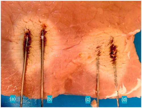
shows how even a moderate applicator mismatching can cause unwanted distortion in the ablation zones. By examining the ablation contours, a hint of comet effect is evidenced for the A and D applicators which exhibited an end-ablation input Г of −9 dB and −7 dB respectively. As expected, the reduced efficiency of the mismatched applicators produces a perceptible ablation asymmetry along the longitudinal direction.
Figure 13. Distortions in temperature behaviours due to the applicator A and B input mismatching.
Discussion
Despite the intrinsic limitations of the numerical analysis, which are due to the difficulty in implementing models that exhaustively describe the dramatic complexity of living tissues, the ex vivo trials demonstrated that the simplified model that was adopted was adequate to compare the performances of multi-probe MW ablative systems operating in synchronous and asynchronous FSS modes.
Numerical and experimental results show a substantial equivalence at a 2.45 GHz ISM frequency between synchronous, asynchronous and FSS feeding modes. Indeed, the heat diffusion phenomenon produces a smoothing in temperature distribution that practically cancels the expected advantages of the coherent feeding. Furthermore, the FSS asynchronous approach presents lower sensitivity to the placement of the applicators in the tissue. A remarkable reduction in the overall system complexity can be attained if the asynchronous solution is implemented by employing FSS technology, and this advantage is augmented by increasing the number of sequentially activated applicators. Finally, FSS technology appears to offer more operational flexibility because phase equalisation among the applicators is not required, and this greatly simplifies procedure planning and increases treatment predictability.
Conclusions
A pair of applicators operating at 2.45 GHz frequency in perfused muscle tissue have been analysed using the most advanced EM and TH simulators. Numerical results, validated by experiments in ex vivo swine tissue, show that
TH synergy plays a marginal role in coherent feeding, as opposed to what happens at 915 MHz frequency where the higher EM penetration depth allows the distance distance between the antennas to be maintained at below the half wavelength in the tissue,
the volume of the achievable TH ablation depends essentially on the total MW energy dispensed and only marginally on the array feeding modality,
FSS technology represents a viable solution for implementing a compact, affordable and highly efficient MW multi-applicator system of the asynchronous type,
multi-applicator technology, along with the use of highly efficient antennas, extends the possibilities for performing treatments using only a pair of uncooled applicators and it allows better procedural control and reproducibility in treating tumours up to 40 mm in diameter.
Acknowledgements
We would like to thank the Centro Interdipartimentale Sviluppo di Nuove Tecnologie Mini-invasive in Chirurgia Oncologica for the highly skilled support they provided in the ex vivo experiments.
Declaration of interest
Cosimo Ignesti discloses his current cooperation with Biomedical, of Florence, Italy, to actively continue the project and its related studies. Guido Biffi Gentili has no relevant relationship to disclose. The authors alone are responsible for the content and writing of the paper.
References
- Habash RWY, Bansal R, Krewski D, Alhafid HT. Thermal therapy, part III: ablation techniques. Crit Rev Biomed Eng 2007;35:37–121
- Diederich CJ. Thermal ablation and high-temperature thermal therapy: overview of technology and clinical implementation. Int J Hyperthermia 2005;21:745–53
- Boni L, Benevento A, Cantore F, Dionigi G, Rovera F, Dionigi R. Technological advances in minimally invasive surgery. Expert Rev Med Devices 2006;3:147–53
- Ahmed M, Brace CL, Lee FT, Goldberg SN. Principles of and advances in percutaneous ablation. Radiology 2011;258:351–69
- Brace CL. Microwave tissue ablation: biophysics, technology and applications. Crit Rev Biomed Eng 2010;38:65–78
- Ryan TP, Turner PF, Hamilton B. Interstitial microwave transition from hyperthermia to ablation: Historical perspectives and current trends in thermal therapy. Int J Hyperthermia 2010;26:415–33
- Brace CL. Radiofrequency and microwave ablation of the liver, lung, kidney, and bone: what are the differences? Curr Probl Diagn Radiol 2009;38:135–43
- Wright AS, Sampson LA, Warner TF, Mahvi DM, Lee FT. Radiofrequency versus microwave ablation in a hepatic porcine model. Radiology 2005;236:132–9
- Simon CJ, Dupuy DE, Mayo-Smith WW. Microwave ablation: principles and applications. Radiographics 2005;25:S69–83
- Brace CL. Microwave ablation technology: what every user should know. Curr Probl Diagn Radiol 2009;38:61–7
- Zhou W, Liang M, Pan H, Liu X, Jiang Y, Wang Y, et al. Comparison of ablation zones among different tissues using 2450-MHz cooled-shaft microwave antenna: results in ex vivo porcine models. PLoS One 2013;8:e71873
- Biffi Gentili G, Gori F, Leoncini M. Electromagnetic and thermal models of a water-cooled dipole radiating in a biological tissue. IEEE Trans Biomed Eng 1991;38:98–103
- Biffi Gentili G, Leoncini M, Trembly BS, Schweizer SE. FDTD electromagnetic and thermal analysis of interstitial hyperthermic applicators. IEEE Trans Biomed Eng 1995;42:973–80
- Wang Y, Sun Y, Feng L, Gao Y, Ni X, Liang P. Internally cooled antenna for microwave ablation: results in ex vivo and in vivo porcine livers. Eur J Radiol 2008;67:357–61
- Lubner MG, Hinshaw JL, Andreano A, Sampson L, Lee FT, Brace CL. High-powered microwave ablation with a small-gauge, gas-cooled antenna: Initial ex vivo and in vivo results. J Vasc Interv Radiol 2012;23:405–11
- Kuang M, Lu MD, Xie XY, Xu HX, Mo LQ, Liu GJ, et al. Liver cancer: increased microwave delivery to ablation zone with cooled-shaft antenna –experimental and clinical studies. Radiology 2007;242:914–24
- Laeseke P, Lee F, van der Weide D, Brace C. Multiple-antenna microwave ablation spatially distributing power improves thermal profiles and reduces invasiveness. J Interv Oncol 2009;2:65–72
- Brace CL, Laeseke PF, Sampson LA, Frey TM, van der Weide DW, Lee FT. Microwave ablation with multiple simultaneously powered small-gauge triaxal antennas: results from an in vivo swine liver model. Radiology 2007;244:151–6
- Wright AS, Lee FT, Mahvi DM. Hepatic microwave ablation with multiple antennae results in synergistically larger zones of coagulation necrosis. Ann Surg Oncol 2003;10:275–83
- Lubner MG, Brace CL, Hinshaw LJ, Lee FTJ. Microwave tumor ablation: mechanism of action, clinical results and devices. J Vasc Interv Radiol 2011;21:S192–203
- Magin RL, Peterson AF. Noninvasive microwave phased arrays for local hyperthermia: a review. Int J Hyperthermia 1989;5:429–50
- Tabuse K, Katsumi M, Kobayashi Y, Noguchi H, Egawa H, Aoyama O, et al. Microwave surgery: hepatectomy using a microwave tissue coagulator. World J Surg 1985;9:136–42
- Reuter NP, Martin RCGI. Microwave energy as a precoagulative device to assist in hepatic resection. Ann Surg Oncol 2009;16:3057–63
- Tabuse K. Basic knowledge of a microwave tissue coagulator. J Hep Bil Pancr Surg 1998;5:165–72
- Liang P, Wang Y, Yu X, Dong B. Malignant liver tumors: treatment with percutaneous microwave ablation – Complications among a cohort of 1136 patients. Radiology 2009;251:933–40
- Wolf FJ, Machan JT, Dupuy DE. Synchronous vs asynchronous microwave ablation: comparison in an ex vivo hepatic bovine model. World Conference on Interventional Oncology, New York City, 2011
- Haemmerich D, Lee FT. Multiple applicator approaches for radiofrequency and microwave ablation. Int J Hyperthermia 2005;21:93–106
- Camart JC, Dubois L, Fabre JJ, Vanloot D, Chive M. 915 MHz microwave interstitial hyperthermia. Part II: array of phase-monitored antennas. Int J Hyperthermia 1993;9:445–54
- Brace CL, Laeseke PF, Sampson LA, van der Weide DW, Lee FT. Switched-mode microwave ablation: less dependence on tissue properties leads to more consistent ablations than phased arrays. Radiological Society of North America meeting, Chicago, IL, 2007
- Ji Z, Brace CL. Expanded modeling of temperature-dependent dielectric properties for microwave thermal ablation. Phys Med Biol 2011;56:5249–64
- Nyborg WL. Solution to bio-heat transfer equation. Phys Med Biol 1988;33:785–92
- Pennes HH. Analysis of tissue and arterial blood temperature in the resting human forearm. J Appl Physiol 1948;1:93–122
- Ai H, Wu S, Gao H, Zhao L, Yang C, Zeng Y. Temperature distribution analysis of tissue water vaporization during microwave ablation: experiments and simulations. Int J Hyperthermia 2012;28:674–85
- Keangin P, Rattanadecho P, Wessapan T. An analysis of heat transfer in liver tissue during microwave ablation using single and double slot antenna. Int Commun Heat Mass Transf 2011;38:757–66
- Rattanadecho P, Keangin P. Numerical study of heat transfer and blood flow in two-layered porous liver tissue during microwave ablation process using single and double slot antenna. Int J Heat Mass Transf 2013;58:457–70
- Keangin P, Wessapan T, Rattanadecho P. Analysis of heat transfer in deformed liver cancer modeling treated using a microwave coaxial antenna. Appl Therm Eng 2011;31:3243–54
- Biffi Gentili G, Ignesti C, Tesi V. Development of a novel switched-mode 2.45 GHz microwave multiapplicator ablation system. Int J Microw Sci Technol 2014;2014:973736
- Saito K, Hayashi Y, Yoshimura H, Ito K. Heating characteristics of array applicator composed of two coaxial-slot antennas for microwave coagulation therapy. IEEE Trans Microw Theory Tech 2000;48:1800–6
- Bernardi P, Cavagnaro M, Pisa S, Piuzzi E. Specific absorption rate and temperature elevation in a subject exposed in the far-field of radio-frequency sources operating in the 10–900-MHz range. IEEE Trans Biomed Eng 2003;50:295–304
- Hoffmann R, Rempp H, Erhard L, Blumenstock G, Pereira PL, Claussen CD, et al. Comparison of four microwave ablation devices: an experimental study in ex vivo bovine liver. Radiology 2013;268:89–97
- Biffi Gentili G, Linari M. A novel thermo-ablative microwave multi-applicator system. RiNEm 2012: 19th Italian National Meeting on Electromagnetism. Rome, Italy, 2012
- Iadanza E, Ignesti C, Biffi Gentili G. Risk management process in a microwave thermal ablation system for CE marking. IFMBE Proc 2013;41:1170–3