
Abstract
Purpose: Size and geometry of the ablation zone obtained by currently available radiofrequency (RF) electrodes is highly variable. Reliability might be improved by matrix radiofrequency ablation (MRFA), in which the whole tumour volume is contained within a cage of x × y parallel electrodes. The aim of this study was to optimise the smallest building block for matrix radiofrequency ablation: a recently developed bipolar 2 × 2 electrode system. Materials and methods: In ex vivo bovine liver, the parameters of the experimental set-up were changed one by one. In a second step, a finite element method (FEM) modelling of the experiment was performed to better understand the experimental findings. Results:The optimal power to obtain complete ablation in the shortest time was 50–60 W. Performing an ablation until impedance rise was superior to ablation for a fixed duration. Increasing electrode diameter improved completeness of ablation due to lower temperature along the electrodes. A chessboard pattern of electrode polarity was inferior to a row pattern due to an electric field void in between the electrodes. Variability of ablation size was limited. The FEM correctly simulated and explained the findings in ex vivo liver. Conclusions: These experiments and FEM modelling allowed a better insight in the factors influencing the ablation zone in a bipolar 2 × 2 electrode RF system. With optimal parameters, complete ablation was obtained quickly and with limited variability. This knowledge will be useful to build a larger system with x × y electrodes for MRFA.
Introduction
Radiofrequency ablation (RFA) is increasingly being used to obtain local control of unresectable primary and secondary liver tumours [Citation1–3]. RFA electrodes, generators and treatment protocols are constantly being improved to increase the ablation diameter [Citation4–16]. Unfortunately, attention to reliability of RFA performance is lagging behind. With current electrodes, large ablation zones can be obtained but their predictability and completeness is problematic. Size and shape of the ablation zone are highly variable and difficult to predict [Citation17–33] even in the most standardised ex vivo experiments (). A standard deviation of the ablation diameter, especially the transverse diameter, of 0.5–1 cm is very common (). In a Gaussian distribution, the mean value ±2 standard deviations describes 95% of lesions. This means a potential difference of 2 to 4 cm between the smallest and the largest ablation zone, with 5% of ablation zones that are still smaller or larger. This poor predictability probably reflects biological variability in structure, composition and perfusion of liver. The size of the ablation zone (assuming identical electrodes and ablation protocol) depends on physical tissue characteristics such as electric and thermal conductivity, density, heat capacity and blood perfusion. Each of these factors can differ according to focal liver architecture (hepatocytes, intertwining arborifications of portal triad and hepatic veins), focal liver composition (water, fat, and proteins), focal parenchymal perfusion rate and proximity of large vessels [Citation34–36]. Ablation size after applying RFA in liver tumours is different than in healthy liver parenchyma and different again in cirrhotic liver [Citation37–40]. Local recurrence rates in clinical studies remain as high today as they were 10 years ago, especially in tumours >3 cm [Citation41–45]. Incomplete ablation not only leads to local recurrence but may render a tumour even more aggressive than before [Citation46–51]. The limitations of RFA continue to stimulate the development of alternative ablation techniques such as cryoablation [Citation52], laser-induced thermotherapy [Citation53], microwave ablation [Citation13,Citation54], irreversible electroporation [Citation55] and electrochemotherapy [Citation56].
Table 1. Variability of ablation size with commercial RF electrodes in ex vivo bovine liver [Citation33].
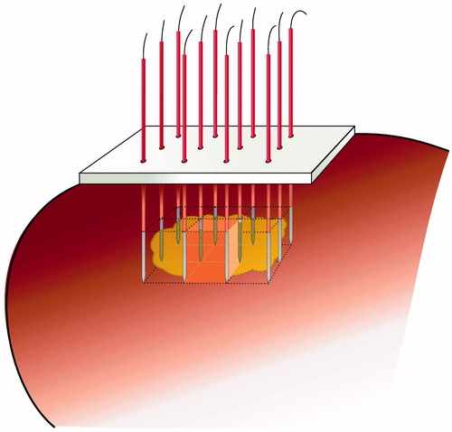
In order to improve reliability and predictability of the ablation zone, we are working on the development of matrix radiofrequency ablation (MRFA) in which the whole tumour volume is contained within a cage of x × y parallel electrodes ().
Figure 1. Matrix radiofrequency ablation. The whole tumour volume is contained within a cage of x × y parallel electrodes. The volume within this cage is the sum of (x − 1) × (y − 1) square blocks, each determined by 2 × 2 electrodes. One cluster of 2 × 2 electrodes is the smallest functional unit of such a matrix of electrodes. Ablation of the whole volume is obtained by activation of the 2 × 2 electrodes around the first block, then rapidly switching to the electrodes around the second block, and so on until impedance rise at all blocks prevents further current flow.
We recently reported on the smallest ‘building block’ for matrix radiofrequency ablation: a cluster of 2 × 2 parallel 3 cm simple needle electrodes activated in a bipolar mode [Citation57]. Complete ablation within the boundaries of the electrodes with minimal ablation outside was obtained in a reproducible way when the interelectrode distance was up to 2 cm [Citation57]. The aim of the current study was to further optimise this bipolar 2 × 2 electrode system and to analyse and understand the factors influencing ablation size and geometry. This knowledge will be useful in constructing (hardware) and steering (software) a system with x × y parallel electrodes.
Materials and methods
Experimental set-up and measurement of lesion size
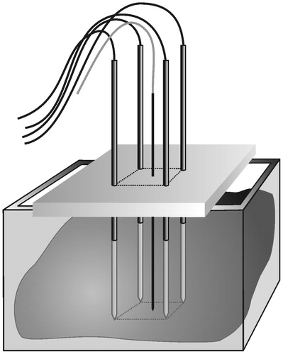
The experimental set-up and the measurement of lesion size have been described in detail recently [Citation57] (). In summary, four simple electrodes (Kirschner wires, Devroe Instruments, Vichte, Belgium) with a 1.8 mm diameter and electrically insulated by a plastic sheath over their entire length except for the last 3 cm at the tip were introduced into a freshly excised beef liver in a vertical and parallel way, in a square configuration. Precise spacing between electrodes was obtained by introducing them through a 3.2 cm thick multi-perforated polyoxymethylene block. Temperature was monitored with a thermocouple inside a saline flushed, non-irrigated, non-electrically activated Tyco cooled-tip single electrode ref CT-2530 (length 25 cm, non-isolated tip 3 cm) (measurement range 10–99 °C, accuracy ± 1 °C) (Tyco Healthcare, Mechelen, Belgium). This passive electrode was inserted in the centre of the square configuration, with its tip in the plane created by the tips of the four radiofrequency electrodes. Electrodes were activated by a Tyco CC-1 generator. A bipolar current field was established between the first pair of ‘positive’ electrodes and the second pair of ‘negative’ electrodes. Power was applied during a predetermined period of time or until current shut-off due to impedance rise.
Figure 2. Ex vivo bovine liver experiments. Temperature was monitored with a thermocouple in the centre of the square determined by the tips of the four radiofrequency electrodes.
Ablation protocol
In a first step, the bipolar 2 × 2 electrode system (3 cm active tip, 2 cm interelectrode distance) was tested in a ‘standard’ set-up using the following parameters based on previous experiments [Citation57]:
power: 50 W, fixed,
duration of ablation: 10 min or until current shut-off due to impedance rise,
electrode diameter: 1.8 mm,
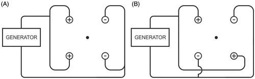
pattern: row pattern, meaning that a bipolar current field was established between a first row of two ‘positive’ electrodes and a second row of two ‘negative’ electrodes ().
In a second step, the parameters of the ‘standard’ set-up were changed one by one.
power: 30, 40, 60, 70, 80 W instead of 50 W,
duration of ablation: 2, 4, 6 min instead of 10 min or until current shut-off due to impedance rise,
electrode diameter: 1.4 and 2.2 mm instead of 1.8 mm,
pattern: chessboard pattern instead of row pattern, meaning that a bipolar current field was established between two ‘positive’ electrodes at the opposite corners of the square and two ‘negative’ electrodes at the other two opposite corners of the square ().
Figure 3. Ex vivo bovine liver experiments: electric wiring scheme. ◯ = electrode; • = thermocouple. (A) standard ‘row’ pattern: the current flows between the first row of two positive electrodes and the second row of two negative electrodes (B) ‘chessboard’ pattern: the current flows between two positive electrodes which are at the opposite corners of the square and two negative electrodes which are at the other two opposite corners of the square.
For each experimental setting, six ablations were created.
The ablation speed was obtained by dividing the volume (cm3) of the tissue contained in between the 2 × 2 electrodes, by the duration of the experiment (s). It was calculated only in case of complete ablation.
Statistical analysis
Numerical data were reported as mean ± standard deviation. A multivariate analysis of data was carried out to take into account the simultaneous influence of power, duration of ablation, electrode diameter and pattern (as analysed in this paper), interelectrode distance (as described in the first paper [Citation57]), electric mode (monopolar versus bipolar) and activation mode (consecutive versus simultaneous versus switching) (electric mode and activation mode will be analysed in a subsequent paper). Duration of ablation, end temperature, time and ablation speed (numerical data) were analysed by linear regression, and completeness of fusion (dichotomous data) by logistic regression. Regression analysis of repeated measures using generalised estimating equation (GEE) was performed to study the values of temperature, impedance and current at every minute. Student’s test was used for some particular comparisons. For evaluation of the influence of power on ablation speed, results between each two groups were compared with paired Student’s t-test after checking for normal distribution of each data sub-set using a Shapiro–Wilk test. One way ANOVA following Bonferroni’s test was applied for comparisons of parameters acquired from multiple conditions. A p value less than 0.05 was considered as statistically significant. Statistical analysis was performed using SPSS 15.0 statistical software (Chicago, IL, USA).
Finite element method analysis
In order to further understand the influence of the aforementioned parameters on ablation size and geometry, we performed a finite element method (FEM) analysis using RAFEM-2, a second generation version of our home-made software for RFA simulation, RAFEM, which has been described in detail before [Citation57,Citation58].
Two partial differential equations are involved. The first is a continuity equation which allows the calculating of the electric potential V at any point of a volume, with σ being the electric conductivity (S/m):
(1)
For simplification, the alternating current of 500 kHz is considered as a direct current. This assumption has been commonly accepted in literature about mathematical modelling of RFA [Citation59].
The second equation is a modified Pennes' heat transfer equation for temperature T in which the terms describing heat transfer by convection (blood perfusion) and heat generation by metabolic processes have been omitted (since the aim was to simulate the ex vivo experiments). A term describing Joule heating by the electric current (J·E) has been added:
(2)
In Equation Equation2(2) , ρ denotes density (kg/m3), c is heat capacity (J/kg·K), k stands for heat conduction coefficient (W/K·m), J means electric current density (A/m2) and E is the electric field (electric potential gradient) (V/m).
Thermal and electric properties of liver and electrodes were taken from Tungjitkusolmun et al. [Citation59] except for the electric and thermal conductivity that were considered to be temperature independent in that paper (and in RAFEM-1) for simplicity. In fact, significant changes in electric and thermal conductivity are seen with rising temperature [Citation60–63]. These changes are taken into account by the second generation version of RAFEM (for details see Appendix 1).
The geometrical model that was used is a box of 100 × 100 × 100 mm. Two pairs of cylinders are standing for two pairs of electrodes of opposite polarity, with a diameter of 1.8 mm and a length of 30 mm including a cone-shaped tip of 2 mm with a 22.5° angle between the tip and the axis of the shaft. They are embedded at a depth of 35 mm beneath the top surface. As electric boundary conditions, zero voltage was set on the left pair of cylinders. To the right pair of cylinders a positive voltage is applied which is determined by a Lagrange multiplier in such a way that the power input into the model was equal to the experiment setting power. As thermal boundary conditions, it was assumed that the heat flux vanished along all the boundaries which means, mathematically, that ∂T/∂n = 0, where n is the outward normal direction of the boundary. The initial temperature of the model was defined to be 20 °C. The 60 °C isotherm was used to predict the ablation zone, based on a careful literature study [Citation57] and on own pilot experiments matching isotherms with the experimentally measured coagulated area (not shown).
Results
Standard set-up
In the standard set-up, temperature went up very smoothly. Impedance first decreased during the first 3 min, then increased from 4 min on until a sudden impedance rise occurred with current shut-off. With constant power output of 50 W, current first increased during the first 3 min, and then decreased from 4 min on until impedance rise with current shut-off. The ablation process took 5.30 ± 0.70 min until current shut-off. End temperature was 77.7 ± 12.4 °C. Ablation was complete in both the axial and the transverse plane. Maximal axial diameter was 4.15 ± 0.21 cm. Maximal transverse diameter was 3.43 ± 0.36 cm.
Power
With increasing power, initial current was higher but the ablation procedure was interrupted more rapidly due to current shut-off (p < 0.001) (). Choosing a lower power allowed us to go on longer with the ablation process and to achieve a higher end temperature (p < 0.001) (). Fusion in both the axial and the transverse plane was always complete up until 60 W and was often incomplete above 60 W (p = 0.056) (). For power values leading to complete ablation (30–60 W), 50 W and 60 W allowed the quickest ablation per cm3 of the tissue contained in between the 2 × 2 electrodes. Ablation speed was 1.22 ± 0.05 cm3/min, 1.84 ± 0.40 cm3/min, 2.29 ± 0.28 cm3/min and 2.51 ± 0.33 cm3/min for 30 W, 40 W, 50 W and 60 W respectively (p < 0.0001 for comparison between all groups simultaneously; p = 0.0581 for paired comparison between 50 and 60 W).
Figure 4. (A) Ex vivo bovine liver experiments: influence of power on current (mean ± SD). (B) Ex vivo bovine liver experiments: influence of power on temperature (mean ± SD) measured in the centre of the square determined by the tips of the four radiofrequency electrodes. (C) Ex vivo bovine liver experiments: influence of power on ablation zone in axial and transverse plane and on mean duration until shut-off.
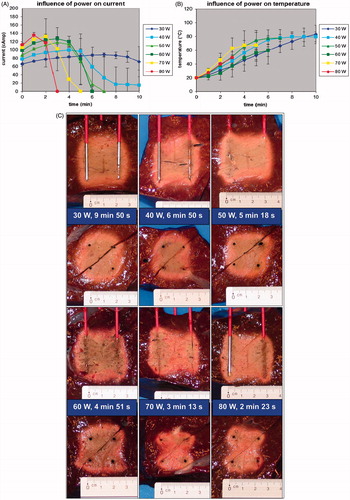
Figure 4. (D) FEM modelling with RAFEM-2: influence of power on temperature distribution in axial and transverse plane at current shut-off.
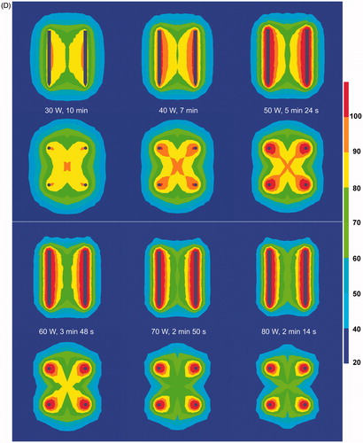
FEM modelling with RAFEM-2 () confirmed that current shut-off was reached earlier with increasing power. Above 60 W, the ablation zone (as defined by the 60 °C isotherm) was incomplete at current shut-off, due to an inhomogeneous temperature distribution (too high around the electrodes, too low at a distance). Temperature distribution was more homogenous with lower power.
Duration
Ablation started off immediately around each electrode. With longer duration, ablation extended to the two strips between the positive and the corresponding negative electrode. Finally, the central area in between those strips was coagulated too (). With longer duration, the chance of complete ablation of the block in between the 2 × 2 electrodes increased. Completeness of fusion in all cases, however, was noticed only when the ablation process was allowed to continue until 10 min or until current shut-off due to impedance rise (p = 0.001). A fixed duration of 6 min or less was insufficient to guarantee complete ablation in all cases.
Figure 5. (A) Ex vivo bovine liver experiments: influence of duration on ablation zone in axial and transverse plane (50 W). (B) FEM modelling with RAFEM-2: influence of duration on temperature distribution in axial and transverse plane (50 W). There are no results for 6 and 10 min because power shut-off in the simulation occurred at 5 min 24 s.
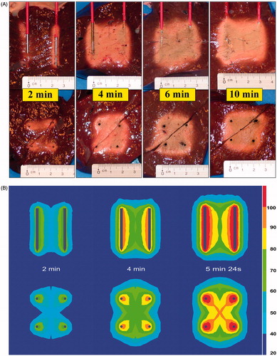
FEM modelling with RAFEM-2 () confirmed that ablation started at the area adjacent to the electrodes. In the transversal plane, the four ablation zones progressively grew towards each other in a cross-like fashion. The area in between two electrodes of the same polarity was coagulated last. In the axial plane, the proximal and distal central area in between the electrodes was coagulated last. Power shut-off in the simulation occurred at 5 min 24 s.
Electrode diameter
With increasing electrode diameter, initial current was similar but the ablation procedure could go on longer before current was shut off by impedance rise (p < 0.001) ().
Figure 6. (A) Ex vivo bovine liver experiments: influence of electrode diameter on current. (B) Ex vivo bovine liver experiments: influence of electrode diameter on temperature measured in the centre of the square determined by the tips of the four radiofrequency electrodes. (C) Ex vivo bovine liver experiments: influence of electrode diameter on ablation zone in axial and transverse plane. (D) FEM modelling with ANSYS: influence of electrode diameter on electric field (V/m) at the cross section of the axial and the transverse plane (distances measured from the centre). (E) FEM modelling with ANSYS: influence of electrode diameter on temperature (°C) after 130 s at the cross section of the axial and the transverse plane (distances measured from the centre).
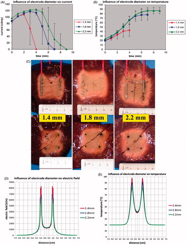
A larger diameter allowed a higher end temperature to be achieved (p < 0.001) (). A temperature of 60 °C was not reached when the electrode diameter was less than 1.8 mm.
Fusion in both the axial and the transverse plane was always complete when electrode diameter was 1.8 or 2.2 mm but was incomplete in five out of six experiments when it was 1.4 mm (). The ablation zone was larger for an electrode diameter of 2.2 mm when compared to an electrode diameter of 1.8 mm. Maximal axial and transverse diameters were 4.57 ± 0.39 cm (p = 0.064) versus 4.15 ± 0.21 cm and 3.82 ± 0.33 versus 3.43 ± 0.36 cm (p = 0.0293), respectively. An electrode diameter of 1.8 mm allowed a quicker complete ablation per cm3 of the tissue in between the boundaries of the 2 × 2 electrodes than a 2.2 mm electrode diameter: 2.29 cm3/min versus 1.89 cm3/min (p = 0.0410).
FEM modelling () showed that the electric field peak and corresponding temperature peak immediately adjacent to the electrode was highest for the smallest electrode diameter. Electric field peak was 8289.3 V/m for the 1.4 mm electrode, 6971.2 V/m for 1.8 mm and 6111.2 V/m for 2.2 mm. At 130 s, temperature along the electrode had already reached 97.7 °C for the 1.4 mm diameter electrode while it was still 91.2 °C and 83.7 °C for 1.8 mm and 2.2 mm electrode respectively. These results were obtained with the linear thermal electric model of ANSYS (i.e. with fixed, temperature independent tissue characteristics) because of its high efficiency in solving problems with large size finite element meshes. In our study on the influence of electrode diameter, the number of finite elements was extra high to obtain detailed information on electric field and temperature immediately along the electrodes: 429,848 for 1.4 mm, 559,381 for 1.8 mm and 720,975 for 2.2 mm. It is beyond the capacity of RAFEM-2 to obtain non-linear solutions (i.e. solutions with temperature-dependent tissue characterisitics) for these high numbers of elements in a reasonable time.
Pattern
When the polarity of the electrodes was organised in a chessboard pattern rather than in a row pattern, initial current (at 0, 1 and 2 min) was higher (p = 0.0172; p < 0.0001; p = 0.0004 respectively) but the ablation procedure was interrupted more rapidly due to current shut-off (p = 0.0083). A row pattern allowed to go on longer with the ablation process and to achieve a higher end temperature (p = 0.0041). A temperature of 60 °C was not reached with a chessboard pattern. Fusion in both the axial and the transverse plane was always complete with a row pattern and was incomplete in five out of six experiments with a chessboard pattern (p = 0.0041) ().
Figure 7. (A) Ex vivo bovine liver experiments: influence of electrode pattern on ablation zone in axial and transverse plane. (B) FEM modelling with RAFEM-2: influence of pattern on electric field (V/m) in axial and transverse plane. (C) FEM modelling with RAFEM-2: influence of pattern on temperature (°C) in axial and transverse plane at current shut-off: 5 min 24 s for row pattern and 3 min 42 s for chessboard pattern.
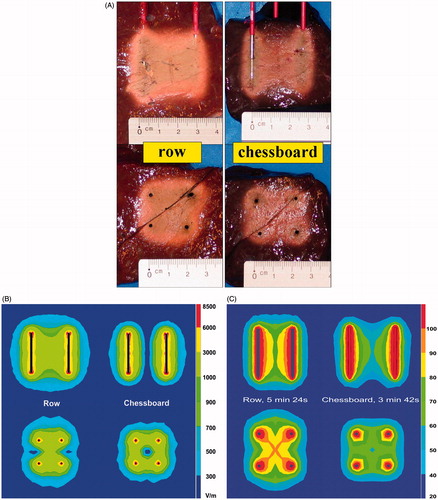
FEM modelling () showed a zero electric field and a corresponding low temperature in the centre between the four electrodes for the chess board pattern in contrast to the row pattern.
Discussion
Background
One of our current research topics is the development of a bipolar 2 × 2-electrode system for reliable RFA of liver tumours. While most modern RFA electrodes have complex designs, we preferred to go back to the simple needle electrodes from the early years of RFA.
Bipolar RFA in the liver between two simple needle electrodes has been described in one of the first papers on RFA in the liver [Citation64,Citation65]. The ablation zone was butterfly shaped. After a short clinical trial [Citation66,Citation67], the concept was abandoned for many years.
Monopolar RFA in the liver with four simple needle electrodes has also been studied in an early succinct study [Citation68,Citation69]. Ablation was incomplete as soon as the electrodes were spaced apart more than 1.5 cm; the clinical results were disappointing [Citation70] and the concept of RFA with four simple electrodes has rapidly been forgotten.
Since then, the bipolar mode and RFA with four electrodes have been explored mainly with novel more complex electrodes: wet [Citation71], cooled [Citation72], expandable [Citation73,Citation74] and blade electrodes [Citation75], and in various combinations[Citation15,Citation76–80].
Only recently, bipolar RFA between two [Citation81] or four [Citation57] simple electrodes has gained renewed interest for ablation of liver tumours [Citation57].
It needs to be mentioned that the current bipolar 2 × 2-electrode system (although developed independently) bears similarities with the Habib sealer, which also consists of a cluster of four simple needle electrodes, with a bipolar current running between two pairs of electrodes [Citation82]. The aim of the Habib sealer is different however: it has been designed to coagulate a narrow plane of healthy liver tissue in the future transection plane to decrease blood loss during hepatectomy, a technique called RF assisted liver resection. Therefore the inter-electrode distance is only 5 mm. The device is applied successively in a linear fashion. The aim of the currently described system on the other hand is to coagulate a wider volume of liver tissue for RFA of liver tumours. Therefore we explored larger interelectrode distances.
A prototype system consisting of 2 × 2 parallel 3 cm simple needle electrodes and a pilot protocol have recently been described [Citation57]. In an ex vivo liver model, complete ablation within the boundaries of the electrodes with minimal ablation outside these boundaries was obtained in a reproducible way when the interelectrode distance was up to 2 cm [Citation57]. The aim of the current study was to further optimise this bipolar 2 × 2 electrode system and to analyse and understand the factors influencing ablation size and geometry. A limitation of our experimental set-up is the use of a thermocouple sensor to monitor the temperature during RFA, because of the potential risk of RF interference [Citation83]. Using fibre-optic sensors would circumvent this concern [Citation84].
Power
A power of 50–60 W was ideal in the experimental setting to obtain a complete ablation in the shortest time. Increasing power to more than 60 W paradoxically led to inferior ablation due to rapid dehydration and carbonisation and premature arrest of current [Citation65,Citation85,Citation86]. Decreasing power to 30–40 W slowed down the ablation process but still induced complete ablation. Although the observation that increasing power above an optimal value may lead to inferior ablation has been reported by others [Citation11,Citation65,Citation85,Citation86], the current FEM modelling () for the first time nicely explains and illustrates the underlying mechanism: with increasing power, temperature distribution becomes increasingly inhomogeneous due to an imbalance between nearly instantaneous heating (mainly due to electrical energy input) around the electrodes and slow heating (mainly due to thermal energy conduction) at a distance.
Duration
The best moment to stop the generator; i.e. the best estimation of the moment when complete ablation was achieved, was not determined by a pre-set duration of time, nor by reaching a pre-set temperature, but by the occurrence of the sudden impedance rise. For each setting of parameters that induced a complete ablation, the variability of the duration of the ablation process was quite large. For example, with duration of 10 min or until current shut-off, the ablation process took 5.30 ± 0.70 min (range 4.6–6.53 min). This variability in duration is probably due to local variability of physical characteristics such as electric and thermal conductivity, which in its turn is due to local variability in tissue structure and composition. An ‘optimal’ fixed duration of time therefore could not be determined. End temperature was not used either to determine the end of the ablation process as it was not found to be a reliable predictor of complete ablation. The reason for this may be that temperature, the way we measured it, gave only focal information on the tissue in the centre of the plane determined by the electrode tips. In order to ensure complete ablation, the ablation had to be continued until the moment of sudden impedance rise. In other words, stopping the generator based on the sudden rise of impedance was the most reliable method to ensure completeness of ablation, as it allowed an ‘automatic’ correction of ablation duration for differences in tissue composition. Of note, such a conclusion could only be drawn from real experiments and not from FEM, since it does not take into account small differences in tissue composition. The outcome of FEM modelling was a single value of current shut off at 5 min 24 s.
Electrode diameter
Our experiments show that increasing the diameter of the electrodes increases the size of the ablation zone for the diameters considered. This has been observed by other authors [Citation16,Citation87–92], although the underlying mechanism has not been studied in depth till now.
Haines [Citation88,Citation93] found that the energy flows in and out of the ablation zone must be equal at thermal equilibrium. He described a linear relationship between the electrode radius and the transverse radius of the ablation zone both in a thermodynamic model and in experiments on (cardiac) tissue [Citation88,Citation93]. He maintained the electrode/tissue interface temperature at 60 °C. At thermal equilibrium, the amount of energy inflow, i.e. (mainly electric) energy crossing the border (surface) between the electrode and the tissue must equal the amount of energy outflow, i.e. (mainly thermal) energy crossing the border (surface) between the ablation zone and the surrounding viable tissue. When electrode/tissue interface temperature is kept constant, increasing electrode diameter r (hence its surface 2πr) linearly increases the ablation zone surface 2πR (hence its diameter R). Although interesting and correct, unfortunately Haines’ model is valid only when temperature at the electrode/tissue interface is kept constant. Other prerequisites are the absence of a sudden impedance rise (which would stop the current flow) and the presence of thermal equilibrium, a condition that is not necessarily met in real life.
The hypothesis that a larger electrode causes a larger ablation diameter due to radial displacement of the tissue [Citation89] can be rejected since the increase in ablation diameter is much larger than the potential radial displacement of tissue. Nevertheless, it has been shown that increased physical contact (force) between the electrode and the tissue improves ablation depth due to better electrical contact [Citation94,Citation95]. A larger diameter may improve the ‘grip’ of the electrode to the tissue and therefore the conduction of current.
Lee [Citation16] hypothesised that a larger electrode creates a higher electric field. Our FEM analysis () shows that in fact the opposite is true. In the tissue immediately adjacent to the electrode, the FEM analysis shows a high and narrow electric field peak and a corresponding high and narrow temperature peak for smaller electrode diameters, explaining rapid overheating along the electrode with dehydration, charring and premature current shut off due to impedance rise. For larger diameters, electric field and temperature peaks were lower, allowing more gradual heating of a larger area.
Increasing the diameter of electrodes up to 2 mm does not seem to compromise safety: when performing liver biopsies, the use of 2 mm (14 gauge) needles was associated with a clinically insignificant slight increase of blood loss compared to the use of 1.2 mm (18 gauge) needles: 1.0 g versus 0.2 g respectively [Citation96]. In hepatic RFA, the bleeding complication rate was similar for 1.8 mm (15 gauge) and 1.4 mm (17 gauge) electrodes [Citation16,Citation92].
Increasing the diameter of electrodes has the additional advantage of increasing stiffness [Citation92] which is useful for accurate electrode placement.
Pattern
Organising the polarity of the electrodes in a novel chessboard pattern rather than in the standard row pattern did not improve completeness of ablation, rather on the contrary. It was hoped the chessboard pattern would facilitate ablation by improving electrical conduction. In the chessboard pattern, current from one ‘positive’ electrode can flow to two equidistant (2 cm) ‘negative’ electrodes whereas in the row pattern these distances are 2 cm and 2.83 cm. Moreover, the symmetry in two dimensions for the chessboard pattern instead of only one dimension for the row pattern was expected to improve fusion of ablation zones around the four electrodes. These expectations were not met, however. The initial current (at 0, 1 and 2 min) was indeed higher but the temperature in the centre between the four electrode tips did not rise well and the ablation procedure was interrupted more rapidly due to current shut-off. FEM modelling () showed the cause of the problem. In the chessboard pattern, the electric field is indeed perfectly symmetrical but it is concentrated around each of the four electrodes with a zero electric field and a corresponding low temperature in the centre between the four electrodes. In the standard row pattern, the electric field is symmetrical in only one dimension but the centre is well ‘covered’ by the fused ablation zones between each pair of opposed electrodes.
FEM modelling
FEM modelling calculating electric fields and isotherms was found to be very useful to understand the reason and the pattern of incomplete ablation by RFA in the current experiments. Our refined FEM modelling program RAFEM-2 takes into account the temperature dependence of electric and thermal conductivity in order to improve realism of the simulation, especially when tissue temperature approaches 100 °C [Citation97].
Zurbuchen found a nearly linear increase in electric conductivity up till 75 °C, a plateau phase between 75–85 °C and a linear decrease between 85–100 °C [Citation60]. The linear increase in electric conductivity up till 75 °C is likely due to the high water and sodium chloride content of liver tissue. In aqueous solutions current is carried physically by ions that travel more rapidly through water with increasing temperature [Citation97]. Above 85 °C, an opposite phenomenon of decreasing electric conductivity is observed, likely due to progressive dehydration [Citation98]. Water behaves like a two-phase liquid in tissue, one that is free and one that is bound the macromolecules of the tissue. The water that is bound to the tissue molecules starts to evaporate at temperatures of about 65 °C [Citation99], and the free water will evaporate at temperatures around 100 °C [Citation99,Citation100]. Above 100 °C, electric conductivity drops dramatically due to complete dehydration and charring [Citation63,Citation101]. By taking into account the temperature dependence of electric conductivity, RAFEM-2 allows the prediction of the moment of current shut-off with a reasonably good correlation with the mean duration in the experiments ( and ). FEM software that does not take into account the temperature dependence of electric conductivity cannot calculate the moment of current shut off. It can only predict when tissue temperature reaches 100 °C, and use this as a raw surrogate for the moment of current shut-off.
RAFEM-2 also takes into account the temperature dependence of thermal conductivity with a linear increase up to 100 °C and a stable value above 100 °C [Citation63], even though the temperature dependence of thermal conductivity has been shown to be less important for realistic simulations than the temperature dependence of electric conductivity [Citation63,Citation102].
Apart from the sharp drop in conductivity due to dehydration, RAFEM-2 currently does not take into account other evaporation-related phenomena such as the energy loss due to evaporation (latent heat) (close to the electrodes), the diffusion of steam through the tissue and the energy release and water deposition due to recondensation (at a distance from the electrodes). We have, however, seriously considered doing so, and have studied the issue in depth. We found three main strategies in the literature to simulate evaporation [Citation63,Citation98,Citation103]. Every model has its advantages and inconveniences [Citation104]. The models mainly focus on the energy loss due to evaporation while the diffusion of steam through the tissue, and the energy release and water deposition due to recondensation are largely ignored, mainly because these phenomena are still poorly understood. Unfortunately, none of these models has been validated so far by comparing their results with experimental radiofrequency ablation data. Two of them are purely theoretical [Citation63,Citation98] and one has been compared only with microwave ablation [Citation103]. Research into quantification of temperature and time-dependent tissue shrinkage due to evaporation has only just started [Citation105,Citation106] and will be valuable for future modelling.
At this moment, we therefore feel uncomfortable to incorporate one of these models into RAFEM-2 until more data become available on their validity. Such validation studies will tell us whether the results of these models are truly more realistic than the current, theoretically imperfect modelling or not.
Variability
Variability of ablation size obtained with any RF electrode (system) including ours seems to be profoundly inevitable due to biological variability of tissue, even in the most standardised ex vivo experiment [Citation33] (). The currently presented bipolar 2 × 2 electrode system tries to circumvent this serious problem by focusing on obtaining a reliable complete ablation within the mechanically imposed boundaries of the 2 × 2 electrodes.
The ablation zone obtained by this device proved to be very reproducible and complete when using the optimal set of parameters as determined in this study (50 W, duration 10 min or until current shut-off, electrode diameter 1.8 mm and row pattern). Ablation was remarkably homogenous, without the typical carbonisation which is often seen in RFA using other electrodes. The rectangular shape of the ablation closely matched the rectangular shape of the volume in between the active parts of the 2 × 2 electrodes. Variability of ablation size, expressed either as standard deviation (SD) or as coefficient of variation = standard deviation/mean diameter (CV), was limited and smaller than for many currently available electrodes, both in the axial and the transverse plane [Citation33] ().
We believe that two factors are contributing to the smaller variability of the ablation size by the 2 × 2 electrode array: the use of the bipolar (versus monopolar) electric mode and the use of plain (versus design) electrodes.
In the bipolar mode, the ablation is to a great extent electrically restricted to the area within the ‘cage’ of the 2 × 2 electrodes. In contrast, in the monopolar mode (e.g. the cooled Covidien electrodes and the expandable AngioDynamics and Boston Scientific electrodes), the transverse diameter of the ablation zone around the electrode is more variable as its boundaries are not mechanically determined but merely depend (apart from the ablation protocol) on the uncontrollable biological variability of tissue characteristics.
The use of plain electrodes has the paradoxical advantage that they perform poorly (i.e. there is little ablation) outside the cage of the 2 × 2 electrodes. In contrast, design electrodes with inbuilt ‘tricks’ to prevent charring along the electrode (such as cooling and two electric poles on one shaft in the bipolar-cooled Celon electrodes) will cause larger ablation zones outside the (cage of three, four or more) electrodes even when used in the bipolar mode.
Matrix radiofrequency ablation
This 2 × 2 electrode array is not a device on its own, ready to be used in patients. The transverse diameter of the ablation zone is no larger than for currently available commercial electrodes (). We see, however, the rectangular ablation zone obtained by this device as the smallest ‘building block’ for matrix radiofrequency ablation, a novel concept aiming at solving the difficult problem of poor predictability of size and shape of the ablation zone obtained by current RF electrodes.
The volume between the electrodes is seen as the only useful part of the ablation zone; the volume outside the electrodes is less interesting although its size should be kept limited to avoid unintended collateral damage. We hope that by adding up these predictable building blocks in matrix radiofrequency ablation, the entire ablation zone will be completely coagulated with little ablation outside.
For matrix radiofrequency ablation, the tumour is pierced by x × y parallel electrodes, either in a preformatted cluster or in a pattern that can be composed freely with individual electrodes inserted through holes in a guiding block. The electrodes determine (x − 1) × (y − 1) rectangular tissue blocks, each boarded by a 2 × 2 electrodes cage. The length of the active parts of each electrode and the distance between two electrodes can be varied within certain limits, as long as the ablation zone within each 2 × 2 electrodes cage is guaranteed to be complete. The sum of the blocks approaches the size and shape of the tumour including a safety margin around (). Ablation of the whole volume is obtained by activation of the 2 × 2 electrodes around the first block, then rapidly switching to the electrodes around the second block, and so on, until impedance has risen at all blocks preventing further current flow. Of note, if successful, matrix radiofrequency ablation will need to be performed by laparotomy since correct parallel placement of electrodes through a percutaneous or laparoscopic approach will be very difficult.
Several steps still need to be taken in the development of matrix radiofrequency ablation. Firstly, additional experiments are needed to study the results with electrodes that have active tips that are shorter and longer than 3 cm and the observed reliable ablation with 2 × 2 electrodes needs to be confirmed when using x × y electrodes.
Secondly, the current ex vivo studies have to be confirmed by in vivo animal studies. Dimensions of ex vivo ablations tend to be larger and more regular than in in vivo perfused liver both for monopolar and bipolar radiofrequency ablation [Citation18,Citation107,Citation108] because of perfusion-mediated cooling [Citation18,Citation109]. However, since matrix radiofrequency ablation, if successful, will be used mainly during laparotomy, the effect of perfusion can be neutralised by performing a Pringle manoeuvre [Citation18]. Results of in vivo animal studies may differ from ex vivo results for other reasons too. Liver tissue electrical resistivity in vivo and ex vivo significantly changes with time since death [Citation110], and starting temperature is higher in vivo (37 °C) than ex vivo (usually 20 °C) [Citation111].
Thirdly, in vivo animal studies will have to be confirmed by a human clinical trial treating primary or secondary tumours in healthy and cirrhotic liver [Citation15]. Unfortunately, a large- animal tumour model is not yet available [Citation112]. Nevertheless ex vivo studies in explanted animal livers remain a good starting point for the pilot investigation and development of novel radiofrequency ablation techniques [Citation113].
Conclusion
In summary, we developed a bipolar 2 × 2 electrode system with simple needle electrodes with a 3-cm active tip and determined its optimal parameter settings. In the optimal setting, the ablation zone was obtained in a short time, very predictable in size and shape and always complete without voids. FEM modelling was very useful to understand the ‘pathogenesis’ of RF ablation zones, including the phenomena around the boiling point. The knowledge gained by the experiments and the FEM modelling will be useful to further develop the novel concept of matrix radiofrequency ablation with the 2 × 2 electrode cluster as the primary ‘building block’.
Acknowledgements
The authors wish to thank Marie-Bernadette Jacqmain, Mr. Axel Bailey and Christian Deneffe for the illustrations. The work is dedicated to the loving memory of Maurits Van Buggenhout, mathematician.
Declaration of interest
This work was partially supported by the grants awarded by the KU Leuven Molecular Small Animal Imaging Centre MoSAIC (KUL EF/05/08); the centre of excellence In vivo Molecular Imaging Research (IMIR) of KU Leuven; and a European Union project Asia-Link CfP 2006- EuropeAid/123738/C/ACT/Multi-Proposal No. 128- 498/111. Yicheng Ni is currently a Bayer Lecture Chair holder.
The authors report no conflicts of interest. The authors alone are responsible for the content and writing of the paper.
References
- Ni Y, Mulier S, Miao Y, Michel L, Marchal G. A review of the general aspects of radiofrequency ablation. Abdom Imaging 2005;30:381–400
- Pan C, Wu P, Yu J, Li W, Huang Z, He N, et al. CT-guided radiofrequency ablation prolonged metastatic survival in patients with liver metastases from nasopharyngeal carcinoma. Int J Hyperthermia 2011;27:549–54
- Nishikawa H, Kimura T, Kita R, Osaki Y. Radiofrequency ablation for hepatocellular carcinoma. Int J Hyperthermia 2013;29:558–68
- Mulier S, Miao Y, Mulier P, Dupas B, Pereira P, de Baere T, et al. Electrodes and multiple electrode systems for radiofrequency ablation: A proposal for updated terminology. Eur Radiol 2005;15:798–808
- Berjano EJ, Burdío F, Navarro AC, Burdío JM, Güemes A, Aldana O, et al. Improved perfusion system for bipolar radiofrequency ablation of liver: Preliminary findings from a computer modeling study. Physiol Meas 2006;27:N55–66
- Lee JM, Han JK, Kim HC, Kim SH, Kim KW, Joo SM, et al. Multiple-electrode radiofrequency ablation of in vivo porcine liver: Comparative studies of consecutive monopolar, switching monopolar versus multipolar modes. Invest Radiol 2007;42:676–83
- Solazzo SA, Ahmed M, Liu Z, Hines-Peralta AU, Goldberg SN. High-power generator for radiofrequency ablation: Larger electrodes and pulsing algorithms in bovine ex vivo and porcine in vivo settings. Radiology 2007;242:743–50
- Weisbrod AJ, Atwell TD, Callstrom MR, Farrell MA, Mandrekar JN, Charboneau JW. Percutaneous radiofrequency ablation with a multiple-electrode switching-generator system. J Vasc Interv Radiol 2007;18:1528–32
- Eisele RM, Neuhaus P, Schumacher G. Radiofrequency ablation of liver tumors using a novel bipolar device. J Laparoendosc Adv Surg Tech A 2008;18:857–63
- Schmidt D, Clasen S, Boss A, Herberts T, Aubé C, Truebenbach J, et al. Comparison of a single perfusion device and an internally cooled cluster device: Laboratory experience in ex vivo liver tissue with longer duration of energy application. J Vasc Interv Radiol 2009;20:524–31
- McGahan JP, Loh S, Boschini FJ, Paoli EE, Brock JM, Monsky WL, et al. Maximizing parameters for tissue ablation by using an internally cooled electrode. Radiology 2010;256:397–405
- Frieser M, Strobel D, Schaber S, Wissniowski TT, Bernatik T, Adis S, et al. [Pulsed radiofrequency ablation using perfused needle applicators in an in vitro trial on bovine liver]. Biomed Tech (Berl) 2010;55:101–7
- Li X, Zhang L, Fan W, Zhao M, Wang L, Tang T, et al. Comparison of microwave ablation and multipolar radiofrequency ablation, both using a pair of internally cooled interstitial applicators: Results in ex vivo porcine livers. Int J Hyperthermia 2011;27:240–8
- Romero-Méndez R, Tobajas P, Burdío F, Gonzalez A, Navarro A, Grande L, et al. Electrical-thermal performance of a cooled RF applicator for hepatic ablation with additional distant infusion of hypertonic saline: In vivo study and preliminary computer modeling. Int J Hyperthermia 2012;28:653–62
- Stoffner R, Kremser C, Schullian P, Haidu M, Widmann G, Bale RJ. Multipolar radiofrequency ablation using 4–6 applicators simultaneously: A study in the ex vivo bovine liver. Eur J Radiol 2012;81:2568–75
- Lee ES, Lee JM, Kim KW, Lee IJ, Han JK, Choi BI. Evaluation of the in vivo efficiency and safety of hepatic radiofrequency ablation using a 15-G Octopus® in pig liver. Korean J Radiol 2013;14:194–201
- Denys AL, De Baere T, Kuoch V, Dupas B, Chevallier P, Madoff DC, et al. Radio-frequency tissue ablation of the liver: In vivo and ex vivo experiments with four different systems. Eur Radiol 2003;13:2346–52
- Mulier S, Ni Y, Miao Y, Rosière A, Khoury A, Marchal G, et al. Size and geometry of hepatic radiofrequency lesions. Eur J Surg Oncol 2003;29:867–78
- Berber E, Herceg NL, Casto KJ, Siperstein AE. Laparoscopic radiofrequency ablation of hepatic tumors: Prospective clinical evaluation of ablation size comparing two treatment algorithms. Surg Endosc 2004;18:390–6
- Montgomery RS, Rahal A, Dodd GD III, Leyendecker JR, Hubbard LG. Radiofrequency ablation of hepatic tumors: Variability of lesion size using a single ablation device. Am J Roentgenol 2004;182:657–61
- Pereira PL, Trubenbach J, Schenk M, Subke J, Kroeber S, Schaefer I, et al. Radiofrequency ablation: In vivo comparison of four commercially available devices in pig livers. Radiology 2004;232:482–90
- Stippel DL, Brochhagen HG, Arenja M, Hunkemoller J, Holscher AH, Beckurts KT. Variability of size and shape of necrosis induced by radiofrequency ablation in human livers: A volumetric evaluation. Ann Surg Oncol 2004;11:420–5
- Frericks BB, Ritz JP, Roggan A, Wolf KJ, Albrecht T. Multipolar radiofrequency ablation of hepatic tumors: Initial experience. Radiology 2005;237:1056–62
- Mulier S, Ni Y, Jamart J, Ruers T, Marchal G, Michel L. Local recurrence after hepatic radiofrequency coagulation: Multivariate meta-analysis and review of contributing factors. Ann Surg 2005;242:158–71
- Frich L, Mala T, Gladhaug IP. Hepatic radiofrequency ablation using perfusion electrodes in a pig model: Effect of the Pringle manoeuvre. Eur J Surg Oncol 2006;32:527–32
- Oshio A, Tamaki K, Shimizu I, Fukuno H, Urata M, Ito S, et al. Double radiofrequency ablation is more extensive with a spherical zone shape compared to single ablation in a pig liver model. J Med Invest 2007;54:28–34
- Boykin RD. Characterization of radiofrequency ablation zones for the purpose of treatment planning. PhD dissertation, University of Texas Health Science Center, Graduate School of Biomedical Sciences, San Antonio, Texas, 2008
- Stippel DL, Bangard C, Prenzel K, Yavuzyasar S, Fischer JH, Hölscher AH. Which parameters are needed for targeting a multitined radiofrequency device – an approach to a simple algorithm. Langenbecks Arch Surg 2009;394:671–9
- Wahba R, Bangard C, Kleinert R, Rösgen S, Fischer JH, Lackner KJ, et al. Electro-physiological parameters of hepatic radiofrequency ablation – a comparison of an in vitro versus an in vivo porcine liver model. Langenbecks Arch Surg 2009;394:503–9
- Bangard C, Rösgen S, Wahba R, Wiemker R, Hellmich M, Reiter H, et al. Large-volume multi-tined expandable RF ablation in pig livers: Comparison of 2D and volumetric measurements of the ablation zone. Eur Radiol 2010;20:1073–8
- Burdio F, Tobajas P, Quesada-Diez R, Berjano E, Navarro A, Poves I, et al. Distant infusion of saline may enlarge coagulation volume during radiofrequency ablation of liver tissue using cool-tip electrodes without impairing predictability. Am J Roentgenol 2011;196:W837–43
- Koda M, Tokunaga S, Matono T, Sugihara T, Nagahara T, Murawaki Y. Comparison between different thickness umbrella-shaped expandable radiofrequency electrodes (SuperSlim and CoAccess): Experimental and clinical study. Exp Ther Med 2011;2:1215–20
- Rathke H, Hamm B, Güttler F, Rathke J, Rump J, Teichgräber U, et al. Comparison of four radiofrequency ablation systems at target volumes of 3 and 5 cm in an ex vivo bovine liver model. Diagn Interv Radiol 2014;20:251–8
- Lu DS, Raman SS, Vodopich DJ, Wang M, Sayre J, Lassman C. Effect of vessel size on creation of hepatic radiofrequency lesions in pigs: Assessment of the ‘heat sink’ effect. Am J Roentgenol 2002;178:47–51
- Liu Z, Ahmed M, Sabir A, Humphries S, Goldberg SN. Computer modeling of the effect of perfusion on heating patterns in radiofrequency tumor ablation. Int J Hyperthermia 2007;23:49–58
- Liu Z, Ahmed M, Gervais D, Humphries S, Goldberg SN. Computer modeling of factors that affect the minimum safety distance required for radiofrequency ablation near adjacent nontarget structures. J Vasc Interv Radiol 2008;19:1079–86
- Haemmerich D, Staelin ST, Tsai JZ, Tungjitkusolmun S, Mahvi DM, Webster JG. In vivo electrical conductivity of hepatic tumours. Physiol Meas 2003;24:251–60
- Liu Z, Ahmed M, Weinstein Y, Yi M, Mahajan RL, Goldberg SN. Characterization of the RF ablation-induced ‘oven effect’: The importance of background tissue thermal conductivity on tissue heating. Int J Hyperthermia 2006;22:327–42
- Laufer S, Ivorra A, Reuter VE, Rubinsky B, Solomon SB. Electrical impedance characterization of normal and cancerous human hepatic tissue. Physiol Meas 2010;31:995–1009
- Mertyna P, Hines-Peralta A, Liu ZJ, Halpern E, Goldberg W, Goldberg SN. Radiofrequency ablation: Variability in heat sensitivity in tumors and tissues. J Vasc Interv Radiol 2007;18:647–54
- Ayav A, Germain A, Marchal F, Tierris I, Laurent V, Bazin C, et al. Radiofrequency ablation of unresectable liver tumors: Factors associated with incomplete ablation or local recurrence. Am J Surg 2010;200:435–9
- Doyle MB, Chapman WC. Radiofrequency ablation for resectable colorectal hepatic metastases: Is it time for a randomized controlled trial? Ann Surg 2010;251:804–6
- Otto G, Düber C, Hoppe-Lotichius M, König J, Heise M, Pitton MB. Radiofrequency ablation as first-line treatment in patients with early colorectal liver metastases amenable to surgery. Ann Surg 2010;251:796–803
- Wong SL, Mangu PB, Choti MA, Crocenzi TS, Dodd GD III, Dorfman GS, et al. American Society of Clinical Oncology 2009 clinical evidence review on radiofrequency ablation of hepatic metastases from colorectal cancer. J Clin Oncol 2010;28:493–508
- Liu CH, Yu CY, Chang WC, Dai MS, Hsiao CW, Chou YC. Radiofrequency ablation of hepatic metastases: Factors influencing local tumor progression. Ann Surg Oncol 2014;21:3090–5
- Mulier S, Ruers T, Jamart J, Michel L, Marchal G, Ni Y. Radiofrequency ablation versus resection for resectable colorectal liver metastases: Time for a randomized trial? An update. Dig Surg 2008;25:445–60
- Ke S, Ding XM, Kong J, Gao J, Wang SH, Cheng Y, et al. Low temperature of radiofrequency ablation at the target sites can facilitate rapid progression of residual hepatic VX2 carcinoma. J Transl Med 2010;8:73
- Kong J, Kong L, Kong J, Ke S, Gao J, Ding X, et al. After insufficient radiofrequency ablation, tumor-associated endothelial cells exhibit enhanced angiogenesis and promote invasiveness of residual hepatocellular carcinoma. J Transl Med 2012;10:230
- Kong J, Kong J, Pan B, Ke S, Dong S, Li X, et al. Insufficient radiofrequency ablation promotes angiogenesis of residual hepatocellular carcinoma via HIF-1α/VEGFA. PLoS One 2012;7:e37266
- Dong S, Kong J, Kong F, Kong J, Gao J, Ke S, et al. Insufficient radiofrequency ablation promotes epithelial-mesenchymal transition of hepatocellular carcinoma cells through Akt and ERK signaling pathways. J Transl Med 2013;11:273
- Xu M, Xie XH, Xie XY, Xu ZF, Liu GJ, Zheng YL, et al. Sorafenib suppresses the rapid progress of hepatocellular carcinoma after insufficient radiofrequency ablation therapy: An experiment in vivo. Acta Radiol 2013;54:199–204
- Ei S, Hibi T, Tanabe M, Itano O, Shinoda M, Kitago M, et al. Cryoablation provides superior local control of primary hepatocellular carcinomas of >2 cm compared with radiofrequency ablation and microwave coagulation therapy: An underestimated tool in the toolbox. Ann Surg Oncol 2014;22:1294–300
- Wichmann JL, Beeres M, Borchard BM, Naguib NN, Bodelle B, Lee C, et al. Evaluation of MRI T1-based treatment monitoring during laser-induced thermotherapy of liver metastases for necrotic size prediction. Int J Hyperthermia 2014;30:19–26
- Lopresto V, Pinto R, Cavagnaro M. Experimental characterisation of the thermal lesion induced by microwave ablation. Int J Hyperthermia 2014;30:110–18
- Yeung ES, Chung MW, Wong K, Wong CY, So EC, Chan AC. An update on irreversible electroporation of liver tumours. Hong Kong Med J 2014;20:313–16
- Miklavčič D, Serša G, Brecelj E, Gehl J, Soden D, Bianchi G, et al. Electrochemotherapy: Technological advancements for efficient electroporation-based treatment of internal tumors. Med Biol Eng Comput 2012;50:1213–25
- Mulier S, Jiang Y, Wang C, Jamart J, Marchal G, Michel L, et al. Bipolar radiofrequency ablation with four electrodes: Ex vivo liver experiments and finite element method analysis. Influence of inter-electrode distance on coagulation size and geometry. Int J Hyperthermia 2012;28:686–97
- Jiang Y, Mulier S, Wang C, Rambo MCD, Chen F, Marchal G, et al. Formulation of 3D finite elements for hepatic radiofrequency ablation. Int J Model, Ident Control 2010;9:225–35
- Tungjitkusolmun S, Staelin ST, Haemmerich D, Tsai JZ, Webster JG, Lee FT Jr, et al. Three-dimensional finite-element analyses for radio-frequency hepatic tumor ablation. IEEE Trans Biomed Eng 2002;49:3–9
- Zurbuchen U, Holmer C, Lehmann KS, Stein T, Roggan A, Seifarth C, et al. Determination of the temperature-dependent electric conductivity of liver tissue ex vivo and in vivo: Importance for therapy planning for the radiofrequency ablation of liver tumours. Int J Hyperthermia 2010;26:26–33
- Watanabe H, Yamazaki N, Kobayashi Y, Miyashita T, Hashizume M, Fujie MG. Temperature dependence of thermal conductivity of liver based on various experiments and a numerical simulation for RF ablation. Conf Proc IEEE Eng Med Biol Soc 2010;2010:3222–8
- Guntur SR, Lee KI, Paeng DG, Coleman AJ, Choi MJ. Temperature-dependent thermal properties of ex vivo liver undergoing thermal ablation. Ultrasound Med Biol 2013;39:1771–84
- Trujillo M, Berjano E. Review of the mathematical functions used to model the temperature dependence of electrical and thermal conductivities of biological tissue in radiofrequency ablation. Int J Hyperthermia 2013;29:590–7
- Jones CD, McGahan JP, Gu W, Brock JM. Percutaneous liver ablation using bipolar radiofrequency electrocautery. Radiology 2007;217:229
- McGahan JP, Gu WZ, Brock JM, Tesluk H, Jones CD. Hepatic ablation using bipolar radiofrequency electrocautery. Preliminary investigation. Acad Radiol 1996;3:418–22
- Rossi S, Di Stasi M, Buscarini E, Quaretti P, Gabargnati F, Squassante L, et al. Percutaneous RF interstitial thermal ablation in the treatment of hepatic cancer. AJR Am J Roentgenol 1996;167:759–68
- Curley SA, Davidson BS, Fleming RY, Izzo F, Stephens LC, Tinkey P, et al. Laparoscopically guided bipolar radiofrequency ablation of areas of porcine liver. Surg Endosc 1997;11:729–33
- Goldberg SN, Gazelle GS, Dawson SL, Rittman WJ, Mueller PR, Rosenthal DI. Tissue ablation with radiofrequency using multiprobe arrays. Acad Radiol 1995;2:670–674
- Goldberg SN, Gazelle GS, Dawson SL, Rittman WJ, Mueller PR, Rosenthal DI. Tissue ablation with radiofrequency using multiprobe arrays. Acad Radiol 1995;2:670–4
- Solbiati L, Ierace T, Goldberg SN, Sironi S, Livraghi T, Fiocca R, et al. Percutaneous US guided radiofrequency tissue ablation of liver metastases: Treatment and follow up in 16 patients. Radiology 1997;202:195–203
- Burdio F, Guemes A, Burdio JM, Castiella T, De Gregorio MA, Lozano R, et al. Hepatic lesion ablation with bipolar saline-enhanced radiofrequency in the audible spectrum. Acad Radiol 1999;6:680–6
- Lee JM, Han JK, Kim SH, Lee JY, Choi SH, Choi BI. Hepatic bipolar radiofrequency ablation using perfused-cooled electrodes: A comparative study in the ex vivo bovine liver. Br J Radiol 2004;77:944–9
- Lee FT, Staelin ST, Haemmerich D, Tungjitkusolmun S, Johnson CD, Mahvi DM. Bipolar RF produces larger zones of necrosis than conventional monopolar RF in pig livers. Radiology 2000;217:229
- Morris DL, Daniel S, Chu F, Lee K. Novel high speed radio frequency (HS-RF) tissue ablation system – initial clinical experience. HPB 2007;9:S246
- dos Santos I, Correia D, Soares AJ, Góes JA, da Rocha AF, Schutt D, et al. A surgical device for radiofrequency ablation of large liver tumors. Physiol Meas 2008;29:N59–70
- Tacke J, Mahnken A, Roggan A, Gunther RW. Multipolar radiofrequency ablation: First clinical results. RoFo 2004;176:324–9
- Lee JM, Han JK, Kim SH, Lee JY, Kim DJ, Lee MW, et al. Saline-enhanced hepatic radiofrequency ablation using a perfused-cooled electrode: Comparison of dual probe bipolar mode with monopolar and single probe bipolar modes. Korean J Radiol 2004;5:121–7
- Zacharoulis D, Khorsandi SE, Vavra P, Dostalik J, Navarra G, Nicholls JP, et al. Pilot study for a new bipolar radiofrequency ablation/aspirator device in the management of primary and secondary liver cancers. Liver Int 2009;29:824–30
- Veenendaal LM, Borel Rinkes IH, van Hillegersberg R. Multipolar radiofrequency ablation of large hepatic metastases of endocrine tumours. Eur J Gastroenterol Hepatol 2006;18:89–92
- Bruners P, Schmitz-Rode T, Günther RW, Mahnken A. Multipolar hepatic radiofrequency ablation using up to six applicators: Preliminary results. RoFo 2008;180:216–22
- Soetaert F, Crevecoeur G, Dupre L. Optimizing bipolar radiofrequency ablation treatment by means of pulsed currents. Conf Proc IEEE Eng Med Biol Soc 2013;2013:3745–8
- Ferko A, Lesko M, Subrt Z, Melichar B, Hoffman P, Dvoràk P, et al. A modified radiofrequency-assisted approach to right hemihepatectomy. Eur J Surg Oncol 2006;32:1209–11
- Andreuccetti D, Bini MG, Ignesti A, Olmi R, Rubino N, Vanni R. EMI-immune thermocouple thermometry in RF hyperthermia systems. IEEE Trans Electromagnetic Compatibility 1989;31:384–9
- Tosi D, Macchi EG, Gallati M, Braschi G, Cigada A, Rossi S, Leen G, Lewis E. Fiber-optic chirped FBG for distributed thermal monitoring of ex-vivo radiofrequency ablation of liver. Biomed Opt Express 2014;5:1799–811
- Clasen S, Geng A, Herberts T, Boss A, Schmidt D, Schraml C, et al. Internally cooled bipolar radiofrequency ablation: Is a lower power output more effective? RoFo 2007;179:282–8
- Zurbuchen U, Frericks B, Roggan A, Lehmann K, Bössenroth D, Buhr HJ, et al. Ex vivo evaluation of a bipolar application concept for radiofrequency ablation. Anticancer Res 2009;29:1309–14
- Cosman ER, Rittman WJ, Nashold BS, Makachinas TT. Radiofrequency lesion generation and its effect on tissue impedance. Appl Neurophysiol 1988;51:230–42
- Haines DE, Watson DD, Verow AF. Electrode radius predicts lesion radius during radiofrequency energy heating. Validation of a proposed thermodynamic model. Circ Res 1990;67:124–9
- Goldberg SN, Gazelle GS, Dawson SL, Rittman WJ, Mueller PR, Rosenthal DI. Tissue ablation with radiofrequency: Effect of probe size, gauge, duration, and temperature on lesion volume. Acad Radiol 1995;2:399–404
- Kim SK, Seo JW. Radiofrequency ablation with a new perfused-cooled electrode using a single pump: An experimental study in ex vivo bovine liver. Cardiovasc Intervent Radiol 2005;28:779–88
- Cosman ER Jr, Gonzalez CD. Bipolar radiofrequency lesion geometry: Implications for palisade treatment of sacroiliac joint pain. Pain Pract 2011;11:3–22
- Park HJ, Lee MW, Song KD, Cha DI, Rhim H, Kang TW, et al. Comparison of therapeutic efficacy and safety of radiofrequency ablation of hepatocellular carcinomas between internally cooled 15-G and 17-G single electrodes. Br J Radiol 2014;87:20130534
- Haines DE, Watson DD. Tissue heating during radiofrequency catheter ablation: A thermodynamic model and observations in isolated perfused and superfused canine right ventricular free wall. Pacing Clin Electrophysiol 1989;12:962–76
- Eick OJ, Gerritse B, Schumacher B. Popping phenomena in temperature-controlled radiofrequency ablation: When and why do they occur? Pacing Clin Electrophysiol 2000;23:253–8
- Yokoyama K, Nakagawa H, Shah DC, Lambert H, Leo G, Aeby N, et al. Novel contact force sensor incorporated in irrigated radiofrequency ablation catheter predicts lesion size and incidence of steam pop and thrombus. Circ Arrhythm Electrophysiol 2008;1:354–62
- Gazelle GS, Haaga JR, Rowland DY. Effect of needle gauge, level of anticoagulation, and target organ on bleeding associated with aspiration biopsy. Work in progress. Radiology 1992;183:509–13
- Chang I. Finite element analysis of hepatic radiofrequency ablation probes using temperature-dependent electrical conductivity. Biomed Eng Online 2003;2:12
- Zhu Q, Shen Y, Zhang A, Xu LX. Numerical study of the influence of water evaporation on radiofrequency ablation. Biomed Eng Online 2013;12:127
- Ramachandran T, Sreenivasan K, Sivakumar R. Water vaporization from heated tissue: An in vitro study by differential scanning calorimetry. Lasers Surg Med 1996;19:413–15
- Nahirnyak VM, Moros EG, Novák P, Klimberg VS, Shafirstein G. Doppler signals observed during high temperature thermal ablation are the result of boiling. Int J Hyperthermia 2010;26:586–93
- Haemmerich D, Chachati L, Wright AS, Mahvi DM, Lee FT Jr, Webster JG. Hepatic radiofrequency ablation with internally cooled probes: Effect of coolant temperature on lesion size. IEEE Trans Biomed Eng 2003;50:493–500
- Watanabe H, Yamazaki N, Isobe Y, Lu X, Kobayashi Y, Miyashita T, et al. Validation of accuracy of liver model with temperature-dependent thermal conductivity by comparing the simulation and in vitro RF ablation experiment. Conf Proc IEEE Eng Med Biol Soc 2012;2012:5712–17
- Yang D, Converse MC, Mahvi DM, Webster JG. Expanding the bioheat equation to include tissue internal water evaporation during heating. IEEE Trans Biomed Eng 2007;54:1382–8
- Fatieieva Y, Almendárez P, Romero-Méndez R, Berjano E, Trujillo M. Comparison of enthalpy method and water fraction method to mathematically model water vaporization during RF ablation. J Adv Biomed Eng Tech 2014;1:8–14
- Farina L, Weiss N, Nissenbaum Y, Cavagnaro M, Lopresto V, Pinto R, et al. Characterisation of tissue shrinkage during microwave thermal ablation. Int J Hyperthermia 2014;30:419–28
- Rossmann C, Garrett-Mayer E, Rattay F, Haemmerich D. Dynamics of tissue shrinkage during ablative temperature exposures. Physiol Meas 2014;35:55–67
- Han JK, Lee JM, Kim SH, Lee JY, Park HS, Eo H, et al. Radiofrequency ablation in the liver using two cooled-wet electrodes in the bipolar mode. Eur Radiol 2005;15:2163–70
- Lee JM, Han JK, Lee JY, Kim SH, Choi JY, Lee MW, et al. Hepatic radiofrequency ablation using multiple probes: Ex vivo and in vivo comparative studies of monopolar versus multipolar modes. Korean J Radiol 2006;7:106–17
- Lu DS, Raman SS, Limanond P, Aziz D, Economou J, Busuttil R, et al. Influence of large peritumoral vessels on outcome of radiofrequency ablation of liver tumors. J Vasc Interv Radiol 2003;14:1267–74
- Haemmerich D, Ozkan R, Tungjitkusolmun S, Tsai JZ, Mahvi DM, Staelin ST, et al. Changes in electrical resistivity of swine liver after occlusion and postmortem. Med Biol Eng Comput 2002;40:29–33
- Lee JM, Han JK, Kim SH, Lee JY, Shin KS, Choi BI. An ex-vivo experimental study on optimization of bipolar radiofrequency liver ablation using perfusion-cooled electrodes. Acta Radiol 2005;46:443–51
- Laeseke PF, Sampson LA, Haemmerich D, Brace CL, Fine JP, Frey TM, et al. Multiple-electrode radiofrequency ablation creates confluent areas of necrosis: In vivo porcine liver results. Radiology 2006;241:116–24
- Bruners P, Lipka J, Günther RW, Schmitz-Rode T, Mahnken AH. Bipolar radiofrequency ablation: Is the shape of the coagulation volume different in comparison to monopolar RF-ablation using variable active tip lengths? Minim Invasive Ther Allied Technol 2008;17:267–74
- Gresho P, Lee RL, Sani RL. On the time-dependent solution of the incompressible Navier-Stokes equations in two and three dimensions. In: Taylor C, Morgan K, eds. Recent Advances in Numerical Methods in Fluids. Swansea: Pineridge Press, 1980, pp. 27–79
- Zienkiewicz OC. The Finite Element Method, 3rd ed. NEWYORK: McGraw-Hill, 1977
- Jewett JW, Serway RA. Physics for Scientists and Engineers, Volume 2, 8th ed. Pacific Grove, PA: Brooks/Cole Cengage Learning, 2010, p. 793
Appendix 1
RAFEM-2 has the following features.
The time-dependent non-linear Equations (Equation1
(1) and Equation2
RFA power is constrained with a Lagrange multiplier [Citation115] to be given values, i.e. 30 W, 40 W, 50 W, 60 W, 70 W and 80 W respectively, as in our experiment settings.
Thermal conductivity k in function of temperature is taken from Trujillo and Berjano (, Case 9, 12) [Citation63]. It is equal to 0.44 W/(m.K) at T = 0 °C, increases linearly up to 0.60 W/(mċK) at T = 100 °C and keeps the same value for T > 100 °C.
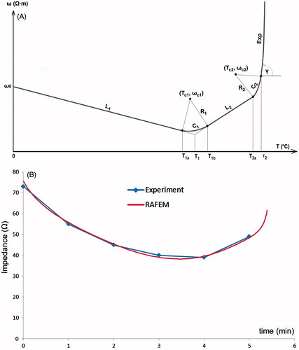
A piecewise temperature-dependent function of resistivity, called Line-Circle-Line-Circle-Exponential (LCLCExp), has been implemented (). Note that resistivity is the inverse of electric conductivity. As resistivity is positively correlated with impedance, it is easier to fit experimental curves of impedance with resistivity than with conductivity. LCLCExp is geometrically composed of two lines (L1 and L2), two arcs (C1 and C2) and an exponentially rising curve, Exp, to model the shut-off. Lines L1 and L2 represent respectively linear decrease and increase of resistivity. Arc C1 intercepts L1 and L2. It was inspired by the plateau in Zurbuchen’s measurements of (in vivo porcine) liver conductivity [Citation60]. Arc C2 is merely for assuring a smooth numerical transition from L2 to Exp. Mathematical expressions of LCLCExp may be written as follows.
For line L1:
(3)
in which ω stands for resistivity, ω0 is resistivity at 0 °C, k1 is the slope of L1, and T1a is temperature at the end of L1.
Figure 8. (A) FEM modelling with RAFEM-2: temperature dependent changes in resistivity during the heating phase are described by a line-circle-line-circle exponential function, Equations Equation3–7, using parameters given in . (B) Determination of parameters in Equations Equation3–7 by fitting ex vivo bovine liver impedance data with RAFEM-2 (power = 50 W, distance between electrodes = 2 cm, diameter of electrode = 1.8 mm, row pattern).
For arc C1:
(4)
in which Tc1 and ωc1 are the coordinates, i.e., temperature and resistivity, at the centre of arc C1, Rc1 is its radius, and T1b is temperature at the end of C1.
For line L2:
(5)
in which ω1 and T1 are resistivity and temperature at the interception of L1 and L2, k2 is the slope of L2, T2a is temperature at the end of L2.
For arc C2:
(6)
in which Tc2 and ωc2 are the coordinates at the centre of C2, Rc2 is its radius, and T2 is temperature at the end of arc C2.
For Exp, the exponential curve [Citation116] starting from temperature T2:
(7)
in which ω2 and k3 are respectively resistivity and the slope of the tangent at the end of C2.
We have determined all the parameters in Equations Equation3–7 by fitting experimental data of impedance with RAFEM-2 (). In such fitting, we repeatedly run RAFEM-2, in adjusting parameters in each run and observing results, so that the computational resistance fits as well as possible the experimental curve of impedance and shut-off time. In RAFEM-2, the resistance is computed as quotient between power, which is constrained to be constant by Lagrange multiplier, and the square of voltage difference applied on pairs of electrodes, which varies in function of temperature change. The final fitting curve is shown in and corresponding parameters are given in . Other parameters in Equations Equation3–7 that are not given in , i.e. Tc1, ωc1, Rc1, Tc2, ωc2 and Rc2 can be determined by simple geometrical analysis. All the simulations with RAFEM-2 in this work have been performed with the parameters in .