
Abstract
Purpose: The aim of this study was to describe the design and characterisation of a miniaturised 434 MHz patch antenna enclosed in a metal cavity for microwave hyperthermia treatment of cancer. Materials and methods: Electromagnetic (EM) field distribution in the near field of a microstrip patch irradiating body tissue was studied using finite element method (FEM) simulations. Antenna miniaturisation was achieved through dielectric loading with very high permittivity, metal enclosure, patch folding and shorting post. Frequency dependent electrical properties of materials were incorporated wherever appropriate using dispersion model and measurements. Antenna return loss and specific absorption rate (SAR) at 434 MHz were measured on muscle phantoms for characterisation. Results: The design was progressively optimised to yield a compact 434 MHz patch (22 mm × 8.8 mm × 10 mm) inside a metal cavity (40 mm × 12 mm) with integrated coupling water bolus (35 mm). The fabricated antenna with integrated water bolus was self resonant at 434 MHz without load, and has better than −10 dB return loss (S11) with 13–20 MHz bandwidth on two different phantoms. SAR at 434 MHz measured using an infrared (IR) thermal camera on split phantoms indicated penetration depth for −3 dB SAR as 8.25 mm compared to 8.87 mm for simulation. The simulated and measured SAR coverage along phantom depth was 3.09 cm2 and 3.21 cm2 respectively at −3 dB, and 6.42 cm2 and 9.07 cm2 respectively at −6 dB. SAR full width at half maximum (FWHM) at 5 mm and 20 mm depths were 54.68 mm and 51.18 mm respectively in simulation, and 49.47 mm and 43.75 mm respectively in experiments. Performance comparison of the cavity-backed patch indicates more than 89% co-polarisation and higher directivity which resulted in deeper penetration compared to the patch applicators of similar or larger size proposed for hyperthermia treatment of cancer. Conclusion: The fabricated cavity-backed applicator is self-resonant at 434 MHz with a negligible shift in resonance when coupled to different phantoms, Δf/f0 less than 1.16%. IR thermography-based SAR measurements indicated that the −3 dB SAR of the cavity-backed aperture antenna covered the radiating aperture surface at 5 mm and 20 mm depths. It can be concluded that the compact cavity-backed patch antenna has stable resonance, higher directivity and low cross polarisation, and is suitable for design of microwave hyperthermia array applicators with adjustable heating pattern for superficial and/or deep tissue heating.
Introduction
Population-based cancer registries in India indicate that cancer of the breast and cervix are the most common cancers amongst Indian women [Citation1]. Lung, stomach and oral cancers are the common cancer sites amongst Indian men. Though the site-specific age-adjusted rate of cancer incidence is lower than in developed countries [Citation2], incidence of cancer is on the rise in India and cancer burden on the nation is a great cause of concern [Citation1,Citation3]. Population-based cancer registries for 2009–2011 indicate incidence rate of breast cancer as 10.3–32.5% compared to cancers at other sites, with higher incidence rates in urban Indian populations. Almost 50% of patients have locally advanced disease [Citation4]. Several clinical trials have demonstrated that the addition of heat to radiation and or chemotherapy treatment of locally advanced and recurrent breast cancers improves clinical outcome [Citation5–8]. This provided us the motivation to develop a compact 434 MHz hyperthermia heating device which could be used to design applicator arrays for site- and region-specific cancers for the Indian scenario.
A literature survey on hyperthermia device development revealed that the following devices were primarily developed for treatment of locally advanced and recurrent breast cancers and soft tissue sarcomas [Citation9,Citation10]: current sheet applicators, dielectric loaded horn and contact flexible microstrip applicator operating at 434 MHz, 140-MHz folded dipole array breast applicator, 915-MHz conformal microwave applicator (CMA) array and scanning ultrasound reflector linear array system (SURLAS). Except for the 915 MHz CMA, devices reported were either rigid or offered limited control on power deposition pattern. The next generation of microwave hyperthermia devices was based on microstrip patch antennas. The 434 MHz rectangular patch and 915 MHz spiral antennas demonstrated the feasibility of low profile and low cost electromagnetic (EM) heating antennas using microstrip patch antennas [Citation11,Citation12]. The hypercollar, consisting of an array of rectangular patch antennas designed for deep-seated head and neck tumours at 434 MHz is undergoing clinical testing [Citation13]. An array applicator made of triangular microstrip antennas containing V-shaped slots and short-circuiting walls has been proposed for time reversal hyperthermia between 500 and 900 MHz [Citation14]. Due to the finite ground plane, performance of the low profile microstrip patch and slot antennas is easily influenced by changes in tissue load and surrounding medium. In this paper we present a miniaturised cavity-backed patch antenna for microwave hyperthermia at 434 MHz with stable resonance near 434 MHz for changes in tissue load and surrounding environment. Miniaturisation is obtained using cavity enclosure, folded design and reactive loading of the patch. The proposed antenna with an integrated water bolus is compact with stable resonance near 434 MHz. The organisation of the paper is as follows. The first section presents the 3D EM model, design and optimisation of the cavity-backed patch antenna and experimental set-up for antenna characterisation on tissue phantoms. Results of the 3D EM simulations for antenna design and optimisation, and experimental validation on tissue phantoms are included in the next section, followed by the discussion and our future work. The final section concludes our work.
Methodology
EM model
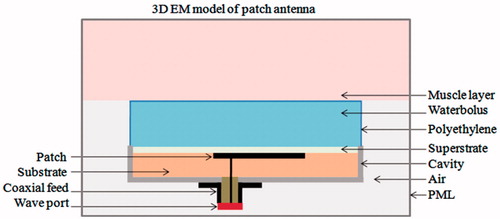
shows the 3D numerical model of the probe-fed cavity-backed patch antenna irradiating a homogeneous tissue layer. The computation model was studied using finite element method (FEM)-based 3D EM simulation software (HFSS®, Ansys, Canonsburg, PA) which solves for the generalised time harmonic vector wave equation
(1)
everywhere inside the computational domain. In Equation (Equation1
(1) )
is the time harmonic electric field,
is the dielectric permittivity of the material assumed to be homogeneous and isotropic,
is the magnetic permeability of the material which is equal to the free space permeability, μ0 in our model, and
is the impressed current density defined at the feed. The antenna was excited using a 50 -Ω SMA type coaxial probe with transverse EM (TEM) mode. The outward-going EM field on the boundaries of the computational domain was absorbed using a perfectly matched layer (PML) to mimic radiation into the surrounding space. The dielectric property of materials used for patch antenna construction was modelled based on literature data and the HFSS® materials database [Citation15]. Dispersive behaviour of dielectric permittivity of muscle tissue and deionised water was modelled using the Cole-Cole model [Citation16], and coaxial dielectric probe measurements (85070E, Keysight Technologies, Santa Rosa, CA) respectively. The computational domain was discretised into tetrahedral elements based on the wavelength inside the individual material. The EM field inside the computational domain was iteratively calculated at the specified frequency, and the computational mesh was adaptively refined until the numerical error between the subsequent iterations was below the specified tolerance, δ. Antenna power coupling efficiency given by the reflection coefficient, S11, and specific absorption rate (SAR) given by
where σ is tissue conductivity and ρ is tissue density, calculated from the near-field distribution, were used to optimise the radiating patch.
Figure 1. A 3D numerical model of the probe-fed cavity-backed resonant patch antenna studied in EM simulation software, HFSS®.
Antenna design
Patch construction
A high permittivity substrate was used for the patch antenna to obtain a compact design. A cylindrical metal enclosure was chosen to shield the patch antenna from effects of finite ground plane and changing surrounding environment, thereby provide stable resonance at 434 MHz [Citation17]. The resonant fields inside the metal enclosure also help in antenna miniaturisation [Citation18] and suppress surface waves in thicker substrate [Citation19]. The substrate and superstrate of the cavity-backed patch were chosen as deionised water to yield a compact antenna with higher directivity [Citation20]. The deionised water also helps cool the applicator during hyperthermia treatment and minimises reflection between the radiating aperture and adjacent water bolus. The cavity-backed patch embedded in deionised water also improves EM coupling between the antenna and tissue load which typically has 70–80% water content. A list of the material properties [Citation15] used in the EM model is summarised in . The patch antenna was optimised to meet the following design criteria: 1) resonance at 434 MHz industrial scientific and medical (ISM) frequency with 90% power coupling to tissue , 2) at least 15 MHz bandwidth (BW) to accommodate small shifts in resonance during clinical use, and 3) a radiating electric field tangential to the tissue to minimise heating at tissue layer interfaces [Citation12,Citation21].
Table 1. Material properties of model domainsa.
Patch evolution
shows the evolution of the cavity-backed patch antenna starting from the simple rectangular patch. The rectangular patch is the simplest design that yields linear current density on the patch and maintains tangentially directed electric field propagating into the tissue. Unlike patch antennas studied in literature, the proposed design is compact due to the finite ground plane inside a metal cavity and reactive loading. Simulations were carried out for cavity-backed rectangular patch of with deionised water as substrate and superstrate for 1 W input power to the 50 Ω coaxial transmission line. In the simulations, frequency was swept from 400 to 500 MHz with less than 2% error in iterative solution (δ0.02) as the convergence criterion. For a given substrate and superstrate, the resonant frequency of a patch is heavily influenced by the maximal length, L and substrate height, h. Thus, simulations were carried out to determine the optimal length for a corner fed patch and 40 mm thick (h1) water bolus. Subsequently, parametric simulations were carried out to determine the optimal substrate height (h.)nd patch width (W). Finally, feed location (xf, yf) was optimised to match the 50 Ω coaxial feed. The influence of water bolus thickness (h1) and cavity height (h2) on antenna performance was also studied. lists the sweep range for the design variables of the cavity-backed rectangular patch of .
Figure 2. Evolution of the compact probe-fed patch antenna inside a metal enclosure. (A) Rectangular patch, (B) folded C-type patch and, (C) C-type folded patch with shorting post near the feed.
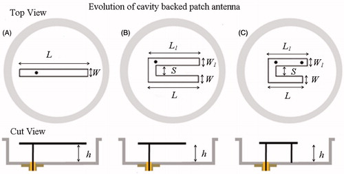
Table 2. Sweep range for the design parameters of cavity-backed rectangular patch ().
The size of the optimised rectangular patch inside the cavity was reduced further by folding the radiating arm into a C-type patch as shown in . A reduction in arm length shifted the resonance to higher frequency due to decrease in inductance of the resonant patch. This was compensated by the capacitive coupling between the folded arms. The resonance and power coupled by the C-type patch were tuned to meet the design criteria by optimising the arm lengths (L, L1) and capacitive coupling provided by the arm separation distance, S. The dimensions of the optimised rectangular patch were used as default values to tune the design parameters of the C-type patch. Subsequently, remaining design parameters (h, W) that influence patch resonant frequency were determined. Finally, the feed location (xf, yf) was optimised to enhance power coupled to the patch by the 50 Ω coaxial feed. The optimised C-type patch was further reduced by reactive loading of the resonant patch as shown in [Citation22]. The reactive impedance provided by the shorting post enabled the length of the C-type patch to be further reduced. The patch dimensions (L, L1) and location of the shorting post were optimised to yield a miniaturised patch antenna for microwave hyperthermia.
Experimental validation
Antenna return loss
The ability to couple power to the human body was studied through antenna return loss (S11) measurements on the following phantoms with high water content: 1) gelatin phantom, and 2) polyacrylamide gel phantom. The solid gelatin phantom was fabricated by mixing polyethylene powder and gelling agent in saline water with 1% salt (NaCl) at 80°C as per the formulation reported for characterisation of EM applicators [Citation23]. Optically transparent polyacrylamide gel phantom simulating muscle tissue was fabricated using the recipe reported in literature [Citation24]. Resonance and power coupled by the miniaturised patch antenna were measured for these high water content tissue phantoms mimicking muscle tissue using a microwave vector network analyser (E5071C, Keysight Technologies, USA).
Antenna SAR
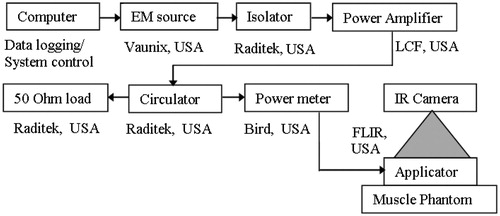
Power deposited by the miniaturised patch was measured on solid split and layered phantoms using infrared thermographic experiments [Citation23,Citation25]. shows the experimental set-up for antenna SAR measurement. Antenna SAR profiles along phantom depth and across the surface at a given depth were characterised by delivering a short pulse of 24 W at 434 MHz for various time durations (45 s, 60 s and 90 s). Temperature distributions on the phantom surface before and after EM exposure were acquired using a medium wave infrared (IR) camera (SC 5000 FLIR, Wilsonville, OR) at the rate of 50 frames per second. Assuming thermal conduction to be negligible (k▿2T ≈ 0) during the short high-power EM pulse, temperature rise in IR thermogram, ΔT from the phantom equilibrium temperature, T0 was used to calculate antenna SAR given by ρC(ΔT/Δt), where C is the phantom specific heat capacity, ΔT = Tf − T0 is the measured thermal gradient for Δt pulse duration, Tf is the phantom temperature after EM exposure. Temperature measurements were recorded for Δt = 45 s, 60 s and 90 s to determine the appropriate time interval with minimal thermal conduction and convection errors for antenna characterisation. Due to the superior thermal stability of polyacrylamide phantom reported in Andreuccetti et al. [Citation24,Citation25], pulse power and duration for antenna SAR charaterisation were determined using split polyacrylamide phantoms. Layered polyacrylamide phantoms, 8 cm × 8.5 cm with 1 cm and 0.5 cm thicknesses were used for surface SAR measurements (XY plane). Split cylindrical phantoms, 10 cm diameter and 5 cm in height were used for SAR depth measurement (XZ plane). Pulse parameters that yielded good agreement between simulation and polyacrylamide phantom SAR measurements were used to measure antenna SAR distribution on gelatin phantom. Layered gelatin phantoms (9 cm × 8 cm × 2 cm) were used for SAR surface measurement (XY plane), and split phantoms (9 cm × 8 cm × 2cm) were used for SAR depth measurement (XZ plane). Full width half maximum (FWHM) of antenna power deposition patterns calculated from phantom thermographic measurements were compared with simulation results. Sliced phantoms for SAR measurements were placed inside an appropriately shaped plastic box to avoid thermal convection effects which could influence the measurements.
Figure 3. Experimental set up for antenna SAR measurement.
Results
Simulation results
Optimisation of the cavity-backed patch
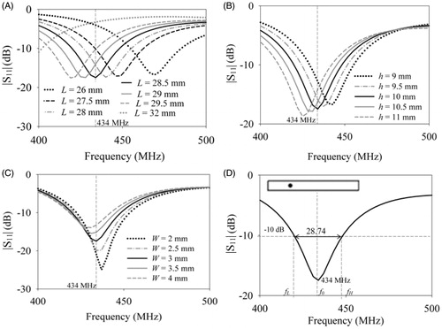
shows the return loss of the rectangular patch inside an 8-mm thick cylindrical aluminium cavity (40 mm ×12 mm) as the patch length, L was swept from 26 mm to 32 mm for W = 3 mm, h = 0 mm, feed location (xf, yf) = (−7.25, 1.5) mm and h1 = 50 mm. Increase in patch length shifted the resonance to lower frequency, since the maximal linear dimension of the patch, L determines the patch resonant frequency, f0 [Citation22]. From the patch length was fixed as 28.5 mm for resonance at 434 MHz and parametric sweep was carried out to determine the optimal dimensions for a miniaturised cavity-backed rectangular patch. show the simulated return loss of the cavity-backed patch for varying substrate height, h. d patch width, W. shows the return loss of the optimised cavity-backed rectangular patch of . The miniaturised patch resonated at 434 MHz with 28.74 MHz BW at −10 dB S11 and induced a linear current density on the patch which maintained a predominantly co-polarised electric field propagating in the water bolus and adjacent muscle tissue,
= 89.9% for the high permittivity superstrate. The dimensions of the optimised cavity-backed rectangular patch were L = 28.5 mm, h = 10 mm, W = 3 mm, xf = −7.25 mm, yf = 1.5 mm. The dimensions of the optimised cavity-backed patch with finite ground is comparable to the designs reported for a patch with a relatively large/infinite ground plane [Citation12,Citation13]. Though the dimensions are comparable, the influence of proximity of the tissue to the finite ground plane and its effect on patch resonant frequency is eliminated in our design.
Figure 4. Influence of the design parameters of the cavity-backed rectangular patch namely, (A) patch length (L), (B) height (h.) and (C) width (W) on return loss . (D) Return loss of the optimised cavity-backed patch with S11 = −17.31 dB at 434 MHz satisfying the design criteria (L = 28.5 mm, h = 10 mm, W = 3 mm).
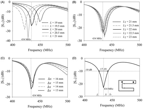
shows the simulated return loss of the folded C-type patch of for variation in patch design parameters. show simulation results for varying arm lengths of the folded patch (L, L1), for W = 3 mm, and default dimensions of cavity-backed rectangular patch. Subsequent optimisation led to a C-type cavity-backed patch with L = 26 mm, L1 = 26 mm, S = 2.8 mm, h = 10 mm, W = 3 mm and (xf, yf) = (−7, 2.9) mm. shows the normalised field distribution of the tangential component of the electric field vector, radiated by the C-type patch in the water bolus and adjacent tissue layer. From it can be observed that the folded C-type patch with smaller maximal dimension compared to the rectangular patch meets the design criteria for microwave hyperthermia.
Figure 5. Simulation results of the cavity-backed folded C-type patch of . Influence of the folded patch lengths namely, (A) the first (L) and (B) second arms (L1) on antenna return loss ; (C) return loss for the optimised C-type patch (L = 26 mm, L1 = 26 mm, h = 10 mm, W = 3 mm, S = 3 mm), and (D) normalised electric field
at 434 MHz in the antenna near field.
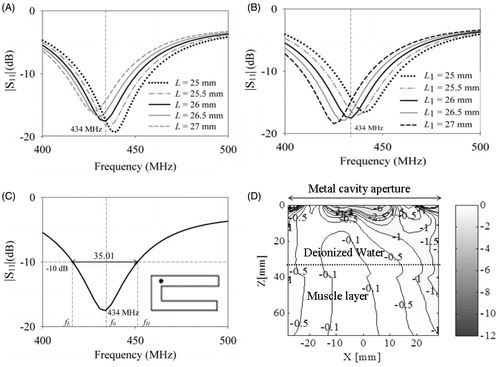
shows the return loss simulations of the cavity-backed C-type patch of with a shorting post. From , we observe that the patch length (L = 20 mm) is much smaller than the rectangular patch (L = 28.5 mm) with the introduction of shorting pin [Citation26]. The shorter arm, L influenced the patch resonance more than the longer arm, L1 Use of shorting wall [Citation27] and capacitive loading [Citation28] have also been proposed for miniaturisation of free space antennas for operation at low frequency. Due to the simple design, reactive loading of the patch with a shorting post near the feed was chosen for patch miniaturisation. shows the influence of the spacing between shorting post and feed, Δx on antenna return loss. The water bolus thickness and configuration are critical for antenna near-field performance, and the simulations indicated that the bolus thickness should be at least 30 mm for stable resonance near 434 MHz. Subsequently, remaining design parameters were optimised to meet the design criteria. shows the return loss of the miniaturised cavity-backed patch antenna designed for microwave hyperthermia. From it can be observed that the reactive loading resulted in stronger resonance at 434 MHz with reduced BW (17. 19 MHz at −10 dB ).
Figure 6. Simulation results of the miniaturised patch with metal enclosure, folded C-type arm and shorting post near the feed. Influence of the lengths of the (A) first (L) and(B) second arms (L1) on antenna return loss ; (C) influence of the spacing between shorting post and feed Δx = 16 mm and (D) return loss of the optimised patch (L = 20 mm, L1 = 22 mm, h = 10 mm, W = 3 mm, S = 3 mm).
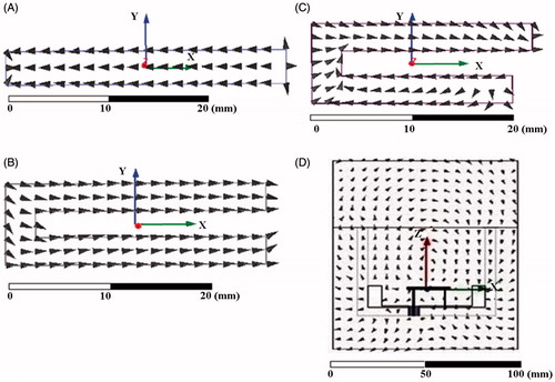
show the orientation of electric current density, induced on the patch surface as the patch was progressively optimised to yield a miniaturised design that meets the design criteria for microwave hyperthermia. The linear current density maintained a co-polarised electric field in the reactive zone of the patch antenna. shows the electric field vector maintained by the miniaturised patch adjacent to the tissue layer. From we observe that the electric field is tangential and continuous near the dielectric boundary between water bolus and muscle tissue. Thus, potential heating at tissue layer interfaces arising due to the normal component of the electric field is eliminated in our design [Citation21].
Figure 7. Orientation of induced current density on the patch surface for the optimised (A) cavity-backed rectangular patch, (B) C-type cavity-backed patch without shorting post, (C) with shorting post; (D) orientation of electric field vector radiated by the miniaturised cavity-backed folded C-type patch with shorting post in the antenna near-field.
Miniaturised patch for microwave hyperthermia
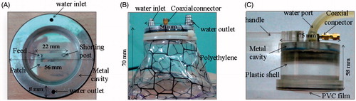
shows the fabricated prototypes of the miniaturised patch antenna for microwave hyperthermia. shows the C-type folded patch with a shorting post near the feed inside a metal cavity. The cavitybacked patch was fabricated using aluminium for light weight and ease of machining. The patch is fabricated from a single metal block using a precision computerised numerical control machining process (±25 µm fabrication tolerance). The inlet and outlet ports of the temperature controlled deionised water were drilled into the metal cavity and were fitted with stainless steel hose barb connectors. The miniaturised patch (22 mm × 8.8 mm × 1 mm) was cut to the dimensions using precision wire cutting with ±10 µm fabrication tolerance. The patch and aluminium cavity were anodised to avoid formation of an oxide layer. The SMA female coaxial feed (Srinar Communications, Chennai, India) with extended inner conductor was screwed to the body of the aluminium cavity and was bonded to the patch with silver conductive epoxy (MG Chemicals, Surrey, BC, Canada). An electrical contact between the shorting post and the ground plane was established using conductive silver epoxy. shows prototype 1 with a flexible water bolus made of 0.3 mm thick soft medical grade PVC film (Renolit, Worms, Germany) fitted to the circumference of the metal cavity. Rubber gaskets were used between the metal cavity and the PVC film to avoid water leakage. Bolus bags of varying height, h1 greater than 35 mm, were fabricated. Due to folding of the bolus layer during phantom testing, prototype 2 shown in was developed with a rigid plastic outer shell and a flexible bottom cover made of soft 0.3 mm thick PVC film. Due to the addition of the plastic shell, the dimensions of the miniaturised patch with integrated rigid water bolus were fine-tuned for resonance at 434 MHz. For the modified patch with rigid plastic outer shell, simulations indicated stable resonance for h1 greater than 30 mm. The cavity-backed miniaturised patch antenna with integrated water bolus of height, h1 = 35 mm was housed in a plastic shell for ease of handling as shown in .
Figure 8. Prototypes of the miniaturised antenna for microwave hyperthermia. (A) C-type folded patch with a shorting post near the feed inside a metal cavity; (B) prototype 1 with flexible 0.3 mm thick PVC water bolus; (C) prototype 2 with rigid side wall to maintain constant bolus thickness and a flexible PVC film at the skin-contacting side.
Antenna characterisation on tissue phantoms
Return loss measurements
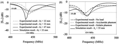
shows comparison between experimental antenna return loss, and simulation result obtained for the optimised dimensions of the miniaturised patch prototype 1. Return loss measurements of prototype 1 () on polyacrylamide phantom for varying water bolus height, h1 indicated single resonance with relatively larger bandwidth compared to the simulation. However, the resonant frequency shifted with bolus height due to the difficulty in maintaining constant bolus height with the flexible water bolus bag during measurements. shows the return loss measurements of prototype 2 with fixed bolus height (35 mm) on different tissue phantoms. It should be observed that the patch is self-resonant at 434 MHz in the absence of load due to the presence of the metal cavity. Also, the shift in resonance for two different muscle phantoms is lower for prototype 2. The return loss of prototype 2 is less than −10 dB at 434 MHz for the muscle phantoms. In the simulations the outer shell of the water bolus was designed as plastic with ɛr = 4 and loss tangent, tanδ = 0. However, the outer shell was constructed using acrylic which has lower permittivity resulting in additional resonance in the shift (). The miniaturised patch has 13–20 MHz BW at −10 dB and is compact compared to other designs reported for microwave hyperthermia at 434 MHz [Citation13, Citation29–31]. Furthermore, it is less influenced by the proximity of the tissue to the applicator ground and to variations in tissue load.
Figure 9. Comparison between return loss measurements of the fabricated miniaturised patch and simulation. Return loss measurements of (A) prototype 1 with flexible water bolus for polyacrylamide phantom, and (B) prototype 2 with fixed water bolus height (h1) and plastic outer shell for no load, poly acrylamide and gelatin phantoms.
Antenna SAR measurements
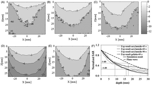
shows experimental and simulated (SAR) patterns of prototype 2 at 434 MHz along the depth of the polyacrylamide and gelatin muscle phantoms (XZ plane) where Z axis indicates depth and X axis indicates surface along the muscle phantom. The SAR pattern is normalised with respect to the maximum value in the measurement plane. show the SAR ρC(ΔT/Δt) measured from IR thermography images of polyacrylamide gel phantom for various pulse durations (45 s, 60 s and 90 s). indicated −3 dB SAR, i.e. 50% of the normalised SAR, measured along the depth as 4.68 mm, 8.7 mm and 11.31 mm respectively for Δt = 45 s, 60 s and 90 s. Increase in FWHM and SAR pattern broadening were observed for larger pulse duration due to heat dissipation aided by thermal conduction inside the phantom during pulse exposure, and thermal convection caused by the finite delay in recording the temperature rise which was about 5 s. shows the simulated SAR at 434 MHz for muscle tissue with ɛr = 56.87, tanδ = 0.59 [Citation16] and ρ = 1000 kg/m3. SAR distribution in polyacrylamide phantom yielded conservative values for SAR FWHM for lesser pulse duration, and is in agreement with simulation () for 60 s pulse duration. Hence, SAR measurement on the split gelatin muscle phantom was conducted for 60 s pulse duration and 26 W at 434 MHz. shows the normalised SAR measured along the depth of the gelatin phantom. Due to the high water content, 25% and 50% SAR contours of the gelatin phantom were relatively larger compared to the polyacrylamide gel phantom and simulation result of . However, the heat deposition pattern is similar for both muscle phantoms and agreed well with the simulation despite variations in phantom dielectric and thermal properties and composition. shows the average depth profiles of normalised SAR obtained from three measurements for different pulse durations. From we observe that SAR measurement on the polyacrylamide phantom for 60 s pulse duration agrees well with thr simulation. It should be noted that the −3 dB and −6 dB SAR along the depth are 8.87 mm and 16.02 mm respectively in the antenna near-field compared to 17.44 mm and 29.38 mm calculated for the plane wave at 434 MHz.
Figure 10. Normalised SAR along the depth of muscle phantoms (XZ plane) for varying pulse duration, Δt. SAR measurements of polyacrylamide gel phantom for (A) 45 s, (B) 60 s and (C) 90 s, (D) simulation results for muscle tissue, (E) normalised SAR of gelatin phantom for Δt = 60 s, (F) comparison of measured and simulated SAR depth profiles.
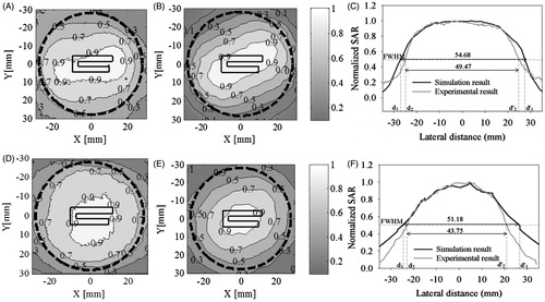
shows the experimental and simulated SAR distribution across the phantom surface (XY plane) at 5 mm and 20 mm depths. The SAR distribution was normalised with respect to the maximum value in the respective measurement planes. Experimental data on layered phantoms were obtained for 60 s pulse duration which had minimal thermal artifacts (). shows the measured SAR distributions at 5 mm depth in the polyacrylamide gel phantom. The dotted black line indicates the outer circumference of the metal cavity with 56 mm diameter and 8 mm wall thickness. It can be observed that SAR measurement at depth is in very good agreement with the simulation result in . shows comparison between measured and simulated SAR profiles at 5 mm depth taken along the centre cut line (y = 0 mm). shows SAR distributions at 20 mm depth measured in gelatin phantom. The corresponding SAR distribution calculated from the simulation is shown in , and comparison between SAR profiles along y = 0 mm is shown in . The SAR distribution is in good agreement with simulations at 5 mm and 20 mm depths with a small broadening due to thermal artifacts associated with this indirect SAR measurement technique [Citation32]. From , we observe that power deposition decays with depth inside the tissue due to wave attenuation as it propagates through the lossy medium. SAR measurements on two different phantoms with dielectric and thermal properties reportedly equivalent to human muscle tissue further confirms that our applicator SAR distribution is not influenced by the choice of phantom.
Figure 11. Normalised SAR at a given depth in muscle phantoms (XY plane). SAR at 5 mm depth for (A) polyacrylamide gel phantom, Δt = 60 s and, (B) simulation result; (C) comparison between measured and simulated SAR profiles along y = 0 mm. SAR surface distribution at 20 mm depth for (D) gelatin phantom, Δt = 60 s, (E) simulation result for muscle tissue, (F) comparison between measured and simulated SAR profiles along y = 0 mm. The dotted black line indicates the outer circumference of the metal cavity (56 mm diameter with 8 mm wall thickness).
provides a summary of maximum rise in temperature (ΔT), maximum SAR, 25% and 50% SAR coverage calculated from phantom measurements for various pulse durations, and simulation results. Measured density of polyacrylamide gel phantom (ρ = 1233 kg/m3) and specific heat capacity, C = 3475 J/kg°C reported in the literature were used for absolute SAR calculations [Citation24]. For the gelatin phantom, specific heat capacity and density of water (C = 4187 J/kg°C, ρ = 1000 kg/m3) were used for SAR calculation [Citation23]. From we observe that temperature rise from thermal equilibrium increases with pulse duration. However, absolute SAR decreased with increase in pulse duration due to heat dissipation through thermal conduction and convection effects associated with thermography studies. Absolute SAR for simulation in calculated using thermal properties of polyacrylamide gel and gelatin phantoms were compared with phantom measurements. Maximum SAR measured for the gelatin phantom (355.89 W/kg) is in good agreement with simulation (367 W/kg) compared to polyacrylamide gel phantom due to the large temperature gradient (ΔT = 5.10°C). Simulated and measured SAR coverage along the depth of the gelatin phantom were 3.95 cm2 and 5.62 cm2 respectively for −3 dB SAR. The −3 dB SAR along the depth of the polyacrylamide gel phantom was measured as 3.21 mm compared to 3.09 mm calculated from the simulation. The 50% SAR coverage at 5 mm depth across the surface of the polyacrylamide gel phantom (XY plane) was measured as 23.12 cm2 and 18.58 cm2 respectively for measurement and simulation. Measurements at 20 mm depth for the gelatin phantom indicated 50% SAR coverage of 25.22 cm2 compared to 18 cm2 for simulation. Normalised SAR measurements at 5 mm and 20 mm depths indicate 50% SAR coverage over the radiating aperture of the cavity-backed miniaturised patch antenna with 40 mm diameter (12.56 cm2). Despite variations in absolute SAR, normalised SAR distributions along depth and across phantom surface at a given depth are in good agreement with simulations.
Table 3. Summary of maximum rise in temperature, ΔTmax, maximum SAR (SARMAX, (°C)) and normalised SAR for polyacrylamide gel and gelatin phantoms for varying heating durations and comparison with simulation results.
Discussion
A compact cavity-backed patch applicator at 434 MHz is presented for hyperthermia treatment. EM field propagation in biological tissues and deionised water was modelled using a dispersion model for the material dielectric property, and 3D simulations for device optimisation were validated with experimental measurements on tissue phantoms. The salient features of the proposed patch are miniaturisation using dielectric loading, reactive loading using a folded arm and shorting pin and improved directivity with low cross polarisation using a metal enclosure. Miniaturisation of the heating element is important for designing an antenna array to deliver controlled power with adjustable spatial heating pattern. Miniaturisation of hyperthermia applicators has been traditionally achieved with dielectric loading [Citation12,Citation13,Citation29]. A comparison with 434 MHz patch applicators reported for hyperthermia treatment in the literature reveals that our applicator (40 mm diameter) is much smaller than the 50 mm × 70 mm theoretical antenna of Andreuccetti et al. [Citation29], 130 mm × 130 mm circular patch of Curto et al. [Citation30], 70 mm × 70 mm dual concentric conductor (DCC) slot antenna of Rossetto et al. [Citation31], and 85 mm diameter spiral antenna of Samulski et al. [Citation11]. Apart from being larger in size, EM field interaction with biological tissues presented in Andreuccetti [Citation29] is based on analytical equations for antenna radiation in free space and employs a lumped LC circuit for input matching. Input matching is obtained in our design by optimising the feed position such that the natural resonance of the patch’s cavity electric field yields maximal response at 434 MHz. Passive reactive loading with patch folding and a shorting pin introduced ino our design further minimised the patch size at 434 MHz [Citation22].
Unlike the rectangular patch radiators with a large ground plane [Citation12,Citation13,Citation29], a relatively small ground plane is used in our design. Though the size of our C-type patch radiator (22 mm × 8.8 mm) is comparable to the 28.7 mm × 8 mm rectangular patch of Paulides et al. [Citation13], the amount of co-polarisation achieved in our cavity-backed patch antenna with smaller ground plane is greater than 90%, while the rectangular patch of Paulides et al. [Citation13] is only greater than 80%. Thus, antenna directivity is far better in our cavity-backed patch antenna despite the smaller ground plane. A sensitivity study of patch dimensions for use in a magnetic resonance (MR) scanner reported in [Citation33] indicated less variation for a larger ground plane size (≥50 mm) and an overall increase in their optimised patch dimensions (31 mm ×8.8 mm) [Citation33]. Thus, ground size of our patch (40 mm diameter) is smaller than other water-loaded patch radiators reported for hyperthermia. Despite the smaller patch and ground dimensions we have demonstrated stable resonance with and without load () and penetration depth of 8.87 mm at −3 dB SAR in tissue phantoms (). Additional simulations carried out in the absence of a metal cavity for our optimised patch dimensions indicated that the patch resonance frequency shifted as high as 36 MHz from 434 MHz and return loss became as high as −6 dB with an increase in patch ground plane from 40 mm to 100 mm diameter. However, the increase in ground plane size in the presence of the cavity had minimal effect on coupled power (−8 dB to −12 dB) and did not shift applicator frequency response. Thus, stable resonance was observed in the presence of the cavity enclosure. This is in agreement with observations reported for free space antennas [Citation17–20]. The effect of metal enclosure on patch size reduction [Citation18] is overshadowed by the high permittivity substrate and superstrate used in our work.
As the patch size is reduced with dielectric loading, substrate height becomes larger which results in undesired surface waves and reduction in antenna radiation efficiency. The metal cavity surrounding the patch reinforces the resonant fields of the patch antenna which behaves as a leaky cavity with low quality factor [Citation22]. The metal cavity surrounding the patch suppresses surface wave propagation, minimises radiation loss inside the patch and reinforces patch resonance [Citation17,Citation18]. Other advantages of the cavity-backed patch radiators that were demonstrated in this paper are (1) low cross polarisation with greater than 89% co-polarised electric field () which minimises discomfort due to unwanted heating at the interface between tissue layers [Citation34], (2) device miniaturisation (40 mm × 10 mm) for design of applicator array with adjustable heating pattern to treat large surface area disease such as chest wall recurrence of breast cancer, and (3) stable resonance with minimal influence from surrounding and variation in tissue load ().
To assess the directivity of our compact patch antenna, additional simulations were carried out to compare the penetration depth of our patch with other patch radiators of similar and larger sizes. Simulations were carried out for the dielectric property and phantom dimensions specified for the respective patch radiator reported in the literature. Typically, larger size implies more radiating cross section, hence, more coupling efficiency. However, −3 dB simulated SAR along the depth from 1 cm onwards was reported as 8 mm for the 50 mm × 70 mm high permittivity patch radiator [Citation29] and is calculated as 7.5 mm for our antenna. Similar observation was made for the 434 MHz circular patch [Citation30]. The simulated peak SAR for 1 W input power on the planar layered model was 5.54 W/kg for the 130 mm × 130 mm circular patch [Citation30]. It is measured as 18.7 W/kg for our cavity-backed antenna indicating higher power coupling. The simulated penetration depths for −3 dB and −6 dB SAR were 7 mm and 9 mm respectively for the circular patch [Citation30], compared to 8.87 mm and 16 mm for our antenna. However, the simulated SAR coverage along the depth is 67.25 cm2 compared to 3.09 cm2 for the proposed antenna due to the larger applicator size. Despite the larger size, SAR deposition in muscle phantom is higher for the proposed antenna due to the higher directivity provided by the metal enclosure. The simulated SAR penetration depth for the 434 MHz conformal DCC aperture array (27.5 cm × 18.75 cm) with 70 mm × 70 mm heating element is approximately 5 mm at −6 dB and 10 mm at −9 dB [Citation31], which is lesser compared to our cavity-backed patch antenna with 16 mm and 24 mm at −6 dB and −9 dB respectively. This is because the slot antenna radiation pattern is bidirectional and its radiation efficiency is poor due to its low profile [Citation22]. Comparison with the 434 MHz spiral antenna indicates that SAR FWHM at 20 mm depth is 75 mm for the 85 mm diameter spiral antenna [Citation11] and 52 mm for our 40 mm diameter applicator. The reduction in SAR FWHM is due to the compact size of our applicator. It is well known that the power deposited by the spiral antenna is more due to its directional radiation pattern compared to the patch radiator. This feature results in higher field inhomogeneity in array design compared to slot and aperture type patch array radiators. This detailed comparison presented here clearly demonstrates that our cavity-backed patch antenna has deeper penetration despite smaller patch and ground plane dimensions. This is due to the higher directivity and low cross polarisation provided by the patch metal enclosure. Applicator characterisation on phantoms presented in this work has motivated us to move forward with the design of an array applicator for microwave hyperthermia. Simultaneously efforts are focused on development of a clinical prototype of the cavity-backed patch applicator for a preclinical study on volunteers. The preclinical study approved by our institute’s ethics committee aims to gather antenna impedance matching to tissue and applicator comfort on healthy and patient volunteers. The outcome of this study will enable us to optimise our single antenna and array design for the development of next generation applicator(s) utilising the self-resonant miniaturised cavity-backed patch antenna.
Conclusion
In this paper we have developed and characterised a miniaturised patch antenna with integrated water bolus for microwave hyperthermia. The proposed antenna is smaller than other 434 MHz patch radiators proposed in the literature. The improved directivity provided by the metal enclosure resulted in higher power deposition at depth compared to other 434 MHz patch radiators of similar and larger sizes. From the characterisation results we conclude that an array of the miniaturised patch antenna could be configured for superficial tissue heating with less field inhomogeneity and adjustable heating patterns for incoherent excitation. A multi-element array of several of the miniaturised patches driven in coherent mode could also be designed to realise an applicator array for microwave hyperthermia treatment of deep seated tumours.
Acknowledgements
The authors thank Krishnan Balasubramanian, professor at the Centre for Non-Destructive Evaluation at the Indian Institute of Technology, Madras, for providing access to VNA and IR thermal camera.
Declaration of interest
This work was sponsored by the New Faculty Research Grant, Indian Institute of Technology, Madras. Grant No : EDD1011522NFSCKAVT. The authors alone are responsible for the content and writing of the paper.
References
- National Cancer Registry Programme. Three year report of population-based cancer registries: 2009–2011. Bangalore: Indian Council of Medical Research, NCDIR-NCRP (ICMR); 2013
- Ferlay J, Shin HR, Bray F, Forman D, Mathers C, Parkin DM. Estimates of worldwide burden of cancer in 2008: GLOBOCAN 2008. Int J Cancer 2010;127:2893–917
- Swaminathan R, Shanta V, Ferlay J, Balasubramanian S, Bray, F Sankaranarayanan R. Trends in cancer incidence in Chennai city (1982–2006) and statewide predictions of future burden inTamil Nadu (2007–16). Natl Med J India 2011;24:72–7
- Shanta V, Swaminathan R, Rama R, Radhika R. Retrospective analysis of locally advanced noninflammatory breast cancer from Chennai, South India, 1990–1999. Int J Radiat Oncol Biol Phys 2008;70:51–8
- Tanaka Y, Imada H, Hiraki Y, Ono S, Maebayashi T, Saito T, et al. The past and present status of clinical hyperthermia in Japan: A survey in 2004 using a questionnaire. Thermal Med 2007;23:1–10
- Zagar TM, Oleson JR, Vujaskovic Z, Dewhirst MW, Craciunescu OI, Blackwell KL, et al. Hyperthermia for locally advanced breast cancer. Int J Hyperthermia 2010;26:618–24
- Zagar TM, Oleson JR, Vujaskovic Z, Dewhirst MW, Craciunescu OI, Blackwell KL, et al. Hyperthermia combined with radiation therapy for superficial breast cancer and chest wall recurrence: A review of the randomised data. Int J Hyperthermia 2010;26:612–17
- Van der Zee J, De Bruijne M, Mens JWM, Ameziane A, Broekmeyer-Reurink MP, Drizdal T, et al. Reirradiation combined with hyperthermia in breast cancer recurrences: Overview of experience in Erasmus MC. Int J Hyperthermia 2010;26:638–48
- Stauffer PR. Thermal therapy techniques for skin and superficial tissue disease. Crit Rev 1999;75:1–41
- Stauffer PR. Evolving technology for thermal therapy of cancer. Int J Hyperthermia 2005;21:731–44
- Samulski TV, Fessenden P, Lee ER, Kapp DS, Tanabe E, McEuen A. Spiral microstrip hyperthermia applicators: Technical design and clinical performance. Int J Radiat Oncol Biol Phys 1990;18: 233–42
- Underwood HR, Peterson AF, Magin RL. Electric-field distribution near rectangular microstrip radiators for hyperthermia heating: Theory versus experiment in water. IEEE Trans Biomed Eng 1992;39:146–53
- Paulides MM, Bakker JF, Chavannes N, Van Rhoon GC. A patch antenna design for application in a phased-array head and neck hyperthermia applicator. IEEE Trans Biomed Eng 2007;54:2057–63
- Trefna HD, Vrba J, Persson M. Evaluation of a patch antenna applicator for time reversal hyperthemia. Int J Hyperthermia 2010;26:185–97
- Ansoft HFSS. Ansys, Canonsburg, PA. Available from http://www.ansys.com
- Gabriel S, Lau RW, Gabriel C. The dielectric properties of biological tissues: III. Parametric models for the dielectric spectrum of tissues. Phys Med Biol 1996;41:2271–93
- Baracco JM, Brachat P. Shielded microstrip subarray with large bandwidth and low cross polarization. Proc IEEE Antennas Propagation Soc Int Symp 1992;1992:203–6
- Karmakar NC. Investigations into a cavity-backed circular-patch antenna. IEEE Trans Microwave Theory Tech 2002;50:1706–15
- Aberle JT. On the use of metallized cavities backing microstrip antennas. In IEEE AP-S Int Symp 1991. London, Ontario, Canada: IEEE, pp. 60–63
- Zavosh F, Aberle JT. Design of high gain microstrip antennas. Microwave J 1999;42(9):138–48
- Montecchia F. Microstrip-antenna design for hyperthermia treatment of superficial tumors. IEEE Trans Biomed Eng 1992;39:580–8
- Garg R, Bhartia P, Bahl I, Ittipiboon A. Microstrip Antenna Design Handbook. Norwood, MA: Artech House; 2001
- Guy AW. Analyses of electromagnetic fields induced in biological tissues by thermographic studies on equivalent phantom models. IEEE Trans Microwave Theory Tech 1971;19:205–14
- Andreuccetti D, Bini M, Ignesti A, Olmi R, Rubino N, Vanni R. Use of polyacrylamide as a tissue-equivalent material in the microwave range. IEEE Trans Biomed Eng 1988;35:275–7
- Surowiec A, Shrivastava PN, Astrahan M, Petrovich Z. Utilization of a multilayer polyacrylamide phantom for evaluation of hyperthermia applicators. Int J Hyperthermia 1992;8:795–807
- Waterhouse RB, Targonski SD, Kokotoff DM. Design and performance of small printed antennas. IEEE Trans Antennas Propagat 1998;46:1629–33
- Pinhas S, Shtrikman S. Comparison between computed and measured bandwidth of quarter-wave microstrip radiators. IEEE Trans Antennas Propagat 1988;36:1615–16
- Rowell CR, Murch RD. A Capacitively loaded PIFA for compact mobile telephone handsets. IEEE Trans Antennas Propagat 1997;45:837–42
- Andreuccetti D, Bini M, Ignesti M, Olmi R, Priori S, Vanni R. A high permittivity patch radiator for single and multielement hyperthermia applicators. IEEE Trans Biomed Eng 1993;40:711–15
- Curto S, See TSP, McEvoy P, Ammann MJ, Chen ZN. In silico hyperthermia performance of a near-field antenna at various positions on a human body model. IET Microw Antennas Propag 2011;5:1408–15
- Rossetto F, Stauffer PR. Theoretical characterization of dual concentric conductor microwave applicators for hyperthermia at 433 MHz. Int J Hyperthermia 2001;17:258–70
- Gladman AV. Infrared Thermographie Measurement of the SAR Patterns of Interstitial Hyperthermia Applicators. Masters thesis, Department of Electrical and Cornputer Engineering, University of Toronto, 1997
- Paulides MM, Bakker JF, Hofstetter LW, Numan WCM, Pellicer R, Fiveland EW, et al. Laboratory prototype for experimental validation of MR-guided radiofrequency head and neck hyperthermia. Phys Med Biol 2014;59:2139–54
- Cheung AY, Neyzari A. Deep local hyperthermia for cancer therapy: External electromagnetic and ultrasound techniques. Cancer Res 1984;44:4736s–44s