
Abstract
Purpose: Clinical phase III trials have shown the benefit of adding hyperthermia to radiotherapy and chemotherapy for head and neck cancer (H&N). The HYPERcollar, a functional prototype capable of applying hyperthermia to the entire H&N region was developed. Specific absorption rate-based hyperthermia treatment planning (HTP) is used to optimise HYPERcollar treatments. Hence, besides treatment quality, reproduction and reproducibility of the HTP are also pivotal. In the current work we analysed the impact of key parameters on treatment quality and completely redesigned the mechanical layout of the HYPERcollar for improved treatment quality and patient comfort. Material and methods: The requirements regarding patient position and the water bolus shape were quantified by simulation studies. The complete mechanical redesign was based on these requirements and non-modellable improvements were experimentally validated. Results: From simulation studies we imposed the required positioning accuracy to be within ±5 mm. Simulation studies also showed that the water bolus shape has an important impact on treatment quality. Solutions to meet the requirements were 1) a redesign of the applicator, 2) a redesign of the water bolus, and 3) a renewed positioning strategy. Experiments were used to demonstrate whether the solutions meet the requirements. Conclusions: The HYPERcollar redesign improves water bolus shape, stability and skin contact. The renewed positioning strategy allows for positioning of the patient within the required precision of ±5 mm. By clinically introducing the new design, we aim at improving not only treatment quality and reproducibility, but also patient comfort and operator handling, which are all important for a better hyperthermia treatment quality.
Introduction
Clinical phase III trials have established a strong benefit from adding hyperthermia (HT) to radiotherapy (RT) and chemotherapy for a number of tumour sites including the head and neck (H&N) region. The impact of superficial HT-generated radiosensitisation on treatment outcome in advanced H&N carcinoma, i.e. metastatic cervical lymph nodes, was first demonstrated by the phase III studies of Valdagni et al. and Amichetti et al. [Citation1–4]. Recently, Huilgol et al. proved an enhancement of RT [Citation5] and promising results for chemoradiation [Citation6] by capacitive HT. Using intracavitary equipment based on a resistive wire, Hua et al. also showed the benefit of adding HT to RT for nasopharynx tumours [Citation7,Citation8].
Based on these clinical results, we developed the HYPERcollar [Citation9] to enable HT treatment of tumours at deep locations in the H&N region also, i.e. more than 4 cm from the skin. The HYPERcollar applicator system features 12 independently controllable channels (power and phase per channel) leading to 23 degrees of freedom to control the energy delivery. For optimisation of the signals applied to the antennas, pre-treatment planning was developed based on 3D numerical electromagnetic simulation tools [Citation10–13]. Moreover, we recently implemented real-time HTP control to facilitate complaint-adaptive treatments [Citation12]. All are important steps towards the reliable and target-conformal application of HT to deeply located tumours in the H&N region.
During HT application, precise control of the heating pattern is required due to the presence of critical tissues in the H&N region. This control enhances treatment quality by improved power targeting, as well as patient comfort by avoiding hotspots during treatment. Rarely, temperature control can be provided by invasive thermometry. Even then, invasive thermometry most often provides only limited localised temperature information [Citation14] and its placement can cause serious discomfort. Therefore, in about 70% of cases, we must fully rely on HTP [Citation13,Citation14], assuming a stable and accurate treatment set-up. Past treatments have shown that water bolus (WB) and positioning properties are unstable and inaccurate over time with the current applicator. This affects treatment quality as well as physical comfort, which in turn decreases the probability of completing the treatment. Given the thermal dose–effect relationship, and the fact that we extensively validated the HYPERcollar model in cylindrical phantoms [Citation9,Citation15], we expect that a new applicator design, which combines improved patient comfort with better control, operator handling and stable treatment quality performance, will further improve clinical outcome.
In this paper we propose a mechanical redesign of the HYPERcollar that improves the quality and comfort during deep H&N HT treatments. As a first step, treatment and equipment were critically observed to find weak points and margins for improvements. At the same time, we performed a simulation study to quantify the influence of the WB shape and positioning on the treatment quality using the HYPERcollar applicator. The results of these first two steps led to a requirement list for the applicator redesign. During the redesign process, separate design solutions were experimentally evaluated before implementation. Finally, the work in this paper and the previously optimised antenna array design [Citation16] were combined in the final redesign, which is currently being constructed.
Material and methods
Initial observations
Initially, the treatment and the equipment involved were observed unobtrusively during treatments, and separately. By this, the behaviour of the patients during the treatment as well as the operator working method could be analysed and questioned, and the required improvements identified. Moreover, in an iterative process, the findings were investigated and the improvements implemented separately and combined afterwards, resulting in a new WB and positioning concept. These concepts led to more precise requirements for the redesign.
Simulation study
To quantify the requirements for the WB shape and for patient positioning, the following simulation studies were performed. From all patients treated with the HYPERcollar, three patients per H&N HT group as defined in Togni et al. [Citation16], were randomly selected to investigate the influence of the positioning error and WB shape on the treatment quality. For completeness, the definitions of the H&N HT group are given below:
Group 1, nasal cavity, paranasal sinus and nasopharynx.
Group 2, oropharynx, oral cavity, hypopharynx, parotid glands.
Group 3, larynx, thyroid, trachea, neck node metastasis.
Models and hyperthermia treatment planning
The patient models used in this study were obtained from the HTP results of H&N HT treatments. In summary, a computed tomography (CT) scan is made for each patient, which is segmented into various tissues [Citation17]. Then, the patient anatomy slices are combined into a 3D model and exported to the electromagnetic (EM) simulation platform SEMCAD X (SPEAG, Zurich, Switzerland) (finite-difference time-domain (FDTD)), along with a computer-aided design model of the HYPERcollar. The location of the patient model within the HYPERcollar model resembles the patient location in the HYPERcollar in the clinic, using the distances A, B and C, see . These distances A, B and C are measured by positioning the patient in the HYPERcollar which is done before the HTP is carried out. EM fields are calculated for each antenna separately, whereafter the E-fields are extracted to MATLAB for importing into the VEDO program. Details of this procedure can be found in Rijnen et al. [Citation12].
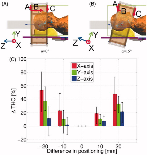
Figure 1. (A, B) HYPERcollar orientations as used during the treatments. (A) is used for H&N HT group 1, while (B) is used for H&N HT group 2 and 3. The arrows A, B and C are the distances with respect to the applicator ring as currently used in hyperthermia treatment planning. (C) Impact of varying patient positioning on target-to-hotspot quotient (THQ). The error bars represent the minimum and maximum differences in THQ.
Impact of water bolus shape
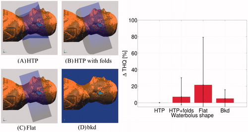
The influence of the WB shape was investigated by varying the WB model in the HTP models. Modelling the exact shapes of the WB proved too difficult to do realistically. Therefore we approximated the large shape variations by the extrema. The WB shapes used are given below and shown in :
: Shape used in HTP for clinical treatments
: Shape used in HTP, but including realistic folds (5 folds in total)
: Straight WB edges in correspondence with the applicator ends, without folds
: Full water background
Figure 2. Left: Different water bolus shapes used in the applicator model to investigate the influence on treatment quality. (A) Hyperthermia treatment planning (HTP) shape, (B) HTP with realistic folds (five in total), (C) straight edges, (D) full water background. Right: Influence of water bolus shapes on target-to-hotspot quotient (THQ), compared to the THQ of the standard HTP model.
Impact of positioning
In the current HYPERcollar procedure, two cases are distinguished. For treatment in H&N HT group 1, the HYPERcollar is not rotated (α = 0°), see . For the treatment of H&N HT groups 2 and 3, the HYPERcollar is always rotated 15°: (α = 15°), see . also shows the respective axis (X, Y, Z) orientations as used in this simulation study.
To evaluate the influence on positioning, the patient model was shifted within the applicator model along the three axes X, Y and Z by ±10 mm and ±20 mm, with respect to the original HTP model, and an HTP was performed for each shifted model.
Evaluation of the simulation study
For the original HTP of each patient included, the specific absorption rate (SAR) distribution was optimised by adjusting the amplitudes and phases of each antenna in the clinical HTP model in order to maximise the target-to-hotspot quotient (THQ), see Equation Equation2(2) [Citation18,Citation19] (the reference HTP). The set of amplitudes and phases obtained from this optimisation was then applied to the other models (same patient, but different patient position or WB shape, hence called the modified HTP) to evaluate ΔTHQ(%), defined by Equation Equation1
(1) . In this way the required positioning accuracy was quantified in each direction along the main axis (X, Y and Z, see ) as well as the effect of changes in the WB shape
(1)
with THQref the THQ of the reference HTP model, i.e. with standard WB or no shift, THQmod the THQ of the modified HTP model, and ΔTHQ the percentage difference in THQ. THQ is defined as in Equation Equation2
(2) below
(2)
with SARtarget the average SAR in the target region and SAR(ν1) as the average SAR in the 1% volume of healthy tissue that contains the highest SAR.
Requirement list
Based on the initial observations, the simulation study and the clinical experience obtained with the HYPERcollar, a requirement list was generated.
Experimental validation of the redesign
Where possible, parts of the redesign were experimentally evaluated to check whether the requirements were met, before proceeding with building the redesigned applicator. For these experiments the following two set-ups were used.
The current HYPERcollar [Citation9].
A small-scale simplified version of the redesigned applicator.
Small-scale set-up
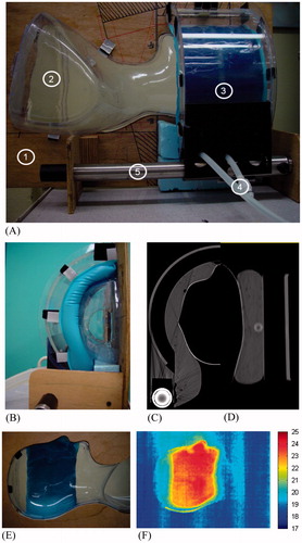
Before the final redesign was approved, a small-scale set-up was realised in order to preliminarily evaluate the performances of the inner WB [Citation20]. show two pictures of the set-up, which resembles one half of the redesigned applicator proposal, without the ground plane and the antennas. A wooden plate allowed the small-scale set-up to be mounted vertically, thereby reproducing the correct applicator orientation. A transparent plastic head-shaped mould could be inserted between the inner WB and the vertical wooden panel. This mould mimicked the patient contour, allowing for evaluating the WB–patient contact in a situation close to reality. Moreover, the patient-conformal contour at the vertical wooden panel was cut out to better evaluate the WB contact from the inside of the mould, see . The inner WB could be filled with water, and the water circulated to perform experiments to evaluate the cooling homogeneity.
Figure 3. (A, B) Pictures of the small-scale set-up. (C, D) Two examples of CT images of the small-scale set-up. (C) Transversal plane slice in correspondence with the middle position of the water bolus shell. (D) Coronal plane slice in correspondence with the applicator horizontal axis. (E) Picture taken through the cavity in the wooden plate to evaluate the water bolus contact from the inside of the mould. The blue part is the inner water bolus. (F) IR picture taken from the same position as (E), showing the temperature distribution of the water bolus through the plastic head-conformal mould.Left side view of the small-scale setup. 1: Wooden plate; 2: Morphologic transparent surface model of a human; 3: Hard-plastic rigid WB holding the inner WB; 4. Tubing for the inflow and outflow of cooled water of the inner WB; 5: Iron glider to shift the WB over as it would be in the applicator redesign.
Volunteer test of the new positioning procedure using the redesigned applicator
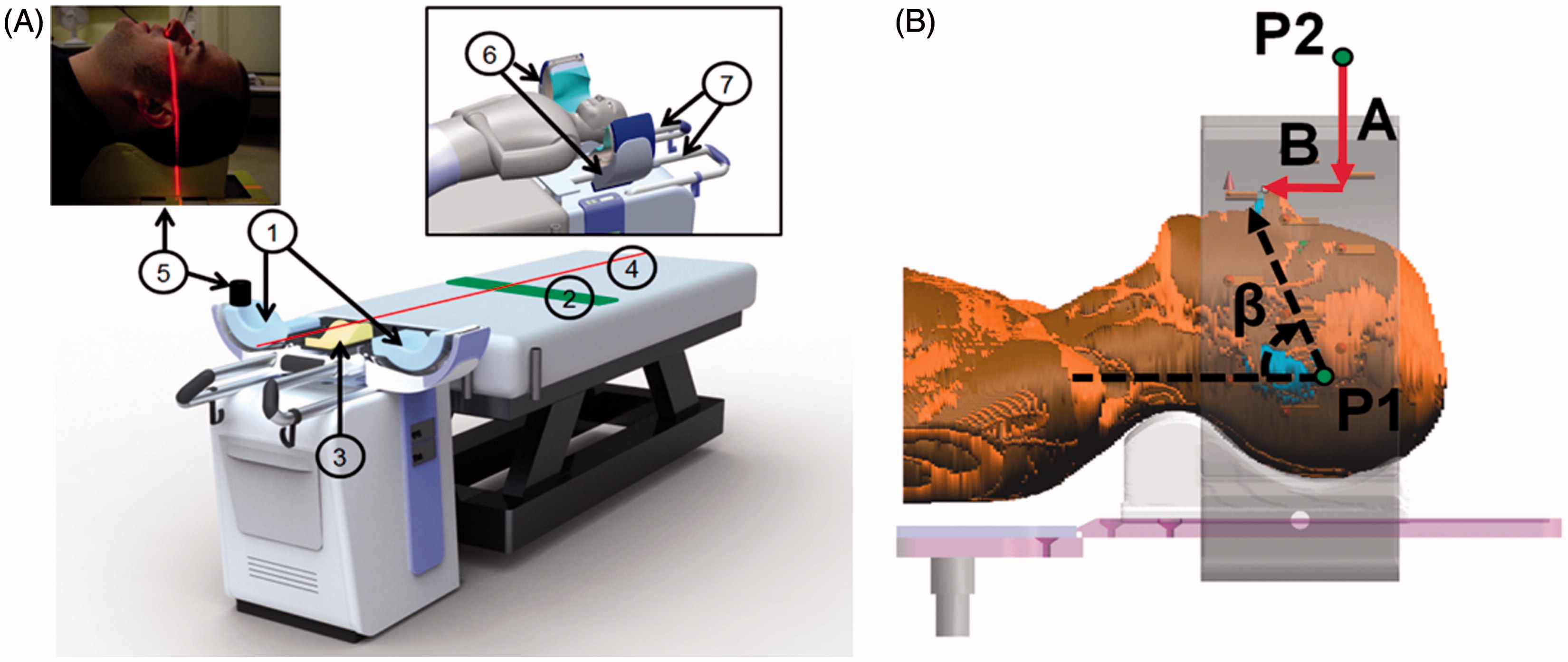
Along with the redesign, a new positioning strategy was developed, as described in the Results section below. The new positioning strategy was tested on healthy volunteers to assess the precision of the new positioning strategy, using the partly constructed redesigned applicator. Each volunteer was positioned in the redesigned applicator according to the renewed positioning strategy. The parameters β, A and B were measured, see . After filling the WB and leaving the volunteer in this position for 5 min, the WB was emptied and the parameters β, A and B remeasured. The difference of β, A and B from the first and second measurement are expressed by Δβ, ΔA and ΔB.
Figure 4. (A) Artist’s impression of the new applicator design and positioning procedure. The patient is initially placed on the treatment bed, with a rough indication of the position for the hips (2) before lowering the upper body. Positioning the H&N on the headrest (HR) (3) is assisted by a middle-sagittal laser-line (4) for aligning the patient. The laser line (5) is used to measure the head rotation, and to adapt the position of the HR accordingly, to set the head rotation such that it matches the head rotation in the hyperthermia treatment planning CT-scan. Second, the two applicator shells (6) slide on the gliders (7) over the patient’s head to the intended position. The shells are then closed, such that they form a cylindrical shape by rotating the shells on the gliders. Finally, the water boluses are filled with water, thereby filling the space between the patient and the outer water boluses. (B) New positioning strategy, showing the distances A and B with respect to a fixed reference point (P2) on the redesigned applicator. The angle β is the angle of a line through the philtrum and the most cranial part of the left ear (P1), with respect to the horizontal plane. The angle β is derived from the radiotherapy CT-scan, while A and B are derived from a test positioning procedure with the patient.
Results
Water bolus observations
To guarantee transport of EM energy and patient skin cooling, a WB is used to fill the space between the antennas and the patient with water. A single circular version is intended to suit every patient in the HYPERcollar. After positioning the patient, water is added to expand the WB. Handling the WB during the filling process is difficult; for example, the direction of the folds and the total water volume can barely be controlled. Intended folds, e.g. for creating breathing cavities, are difficult to obtain and to reproduce in following treatments. Pressure and foil resistance can lift the head upwards or even cause shifting in the transversal plane. Therefore, the WB shape varies significantly between treatments. This made it difficult to model the HYPERcollar’s WB shape accurately, introducing a mismatch between HTP and clinical practice.
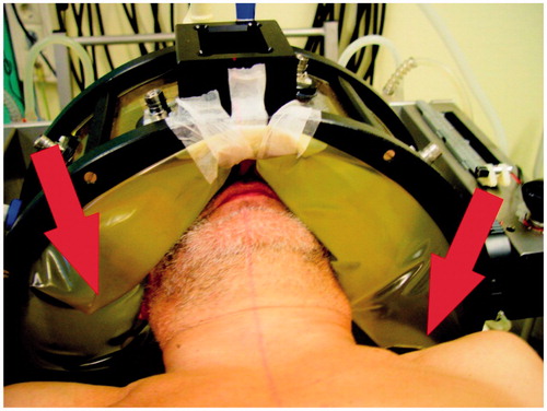
The temperature in the large water volume in the WB of the HYPERcollar appeared hard to control. Also, the folds in the HYPERcollar’s WB block the water circulation, as they divide the WB into different sections, see . This results in inhomogeneous cooling of the antennas, which affects their performance, and inhomogeneous cooling of the patient skin, which can cause hotspots or muscle stiffness.
Figure 5. Patient in the HYPERcollar. Folds can be seen in the water bolus on both sides of the patient. The red arrows emphasise the folds that divide the water boluses into different sections and thereby block the water circulation. Also note the sticky tape that is used to create an air cavity for breathing.
Influence of water bolus shape variations on target-to-hotspot quotient
The WB simulation study shows that the differences in shape have an important impact on ΔTHQ, see . For the nine evaluated patient models, the ΔTHQ enhances by an average of 11% with increments of about 80% in the worst case. These crude simulations demonstrate the importance of the WB shape; which should be predictable and reproducible. Note that quantified tolerances are difficult to study due to the unpredictable and highly non-linear behaviour of the shape of the current WB. The influence of the flat WB shape on ΔTHQ is the highest due to the fact that the target region extends, in caudal direction, outside the flat WB for four of the nine evaluated patient models.
Water bolus redesign
Each applicator-half consists of an outer and an inner WB. The outer WB consists of a rigid, transparent PMMA (polymethyl methacrylate) shell of 1 mm thickness around the antennas on the back plane, which protects the antennas and allows control of the water temperature to guarantee an adequate impedance matching during treatment.
The inner WB, see , should ensure a proper connection between the outer WB and the patient’s skin.
Figure 6. Proposal of the new inner water bolus design. (1) Open cell, water-permeable polypropylene foam insert, surrounded by a non-elastic foil (2). The foam insert should ensure a predictable shape after filling, since the elastic styrene ethylene butylene styrene (SEBS)-foil (3) exactly fits the foam, and during filling the water bolus will mostly expand in the direction of the patient’s skin and not to the sides. Water tubes (4) are inserted for water circulation and hence, temperature homogeneity.
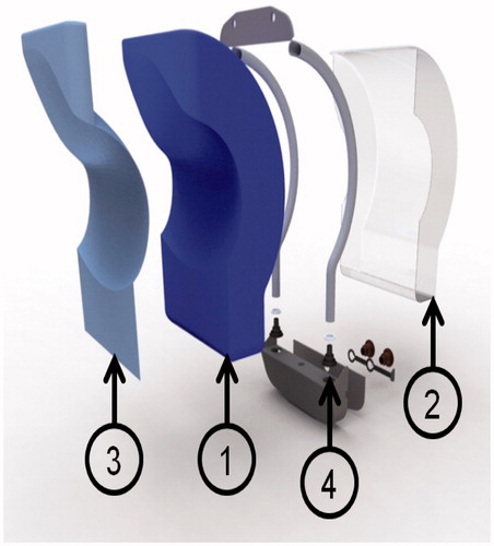
The foam and foil WB inhibits a pre-shaped breathing option, increasing reproducibility: a triangular cavity from the top of the nose down to the chin for the treatment of H&N HT group 1, or a triangular cavity from the nose to the forehead for the treatment of H&N HT groups 2 and 3.
Experimental assessment of the bolus shape reproducibility and fold reduction
A visual inspection of the small-scale setup, including the inner WB, already shows a strong improvement (see ); no folds are seen, and the WB is well connected to the patient, see also Togni et al. [Citation20]. For a more extensive evaluation, the small-scale set-up was fully imaged using a CT-scan (resolution: 0.72 by 0.72 mm in the transverse plane, and 2.5 mm in the longitudinal direction). Two examples of the CT-scan images are shown in . shows a CT-slice in the transversal plane in correspondence of the middle position of the WB shell. This picture clearly shows that this design guarantees a really good contact between the inner WB and the head-shaped mould as well as with the external WB shell. Moreover, analysis of the entire CT-scan did not show the presence of any kind of air folds between the WB and the patient-conformal mould.
Experimental assessment of the WB cooling homogeneity
The small-scale set-up of was also used to verify the cooling uniformity of the WB, see also Togni et al. [Citation20]. This experiment was performed by circulating warm water (25 °C) within the WB till a steady-state temperature was achieved, and by measuring the temperature distribution in the inner part of the patient using an infrared thermocamera (Avio Neo Thermo TVS-600, Nippon Avionics, Tokyo, Japan). The pictures were made through the hole in the wooden plate, and through the mould, which was possible because of the limited thickness of the mould (around 2 mm) see . The temperature of the surrounding air was 17 °C. Although this method provides only a qualitative evaluation, pictures do show that the water circulation spreads the temperature uniformly, i.e. a homogeneous cooling over the WB surface. The lack of cold-spots in the infrared picture indicates that no folds exist in this set-up, which was also shown by the evaluation with the CT-scan.
Current positioning procedure
In the current positioning procedure, the patient is initially placed on the middle of the bed and headrest (HR). Then the bed is shifted into the applicator, such that the distances A, B and C related to the antenna ring match those of the planning, see . Finally, the WB is filled around the patient’s head. Positioning is important for an accurate, target-conformal application of H&N HT [Citation14]. Clinical experience has shown that positioning and rotation of the patient head deviations could add up to several centimetres during a deep H&N HT treatment [Citation14]. Because of their mutual dependencies, positioning and rotation can be hard to set in the current procedure.
Influence of positioning on target-to-hotspot quotient
The results of the positioning simulation study, see , show that an error of 10 mm in the X direction results in an increase of THQ of 21% on average while in the Y and Z direction the increase is limited to 10% and 5%. For errors of 20 mm the trend is similar, but the hotspot relevance in all directions is above 30% on average, except for Z, where this level is reached in the worst case only. Although a criterion for the maximum ΔTHQ that is allowed is yet unknown, we concluded the following from the positioning simulation study: first, the influence on ΔTHQ is the highest for a shift on the X-axis, the left–right positioning of the patient should be monitored closely during treatment using the laser alignment. Second, a shift along the Y-axis has a larger influence on the average ΔTHQ than a shift along the Z-axis, hence the requirement on the shift along the Y-axis should be more stringent than along the Z-axis. Based on this positioning simulation study, the requirements of the patient positioning were chosen to be within ±5 mm.
Renewed positioning strategy
The new positioning strategy is described in . This new positioning strategy uses lasers to aid in matching the patients head rotation in both the middle-sagittal plane and the middle-coronal plane.
Positioning test with volunteers using the redesigned applicator
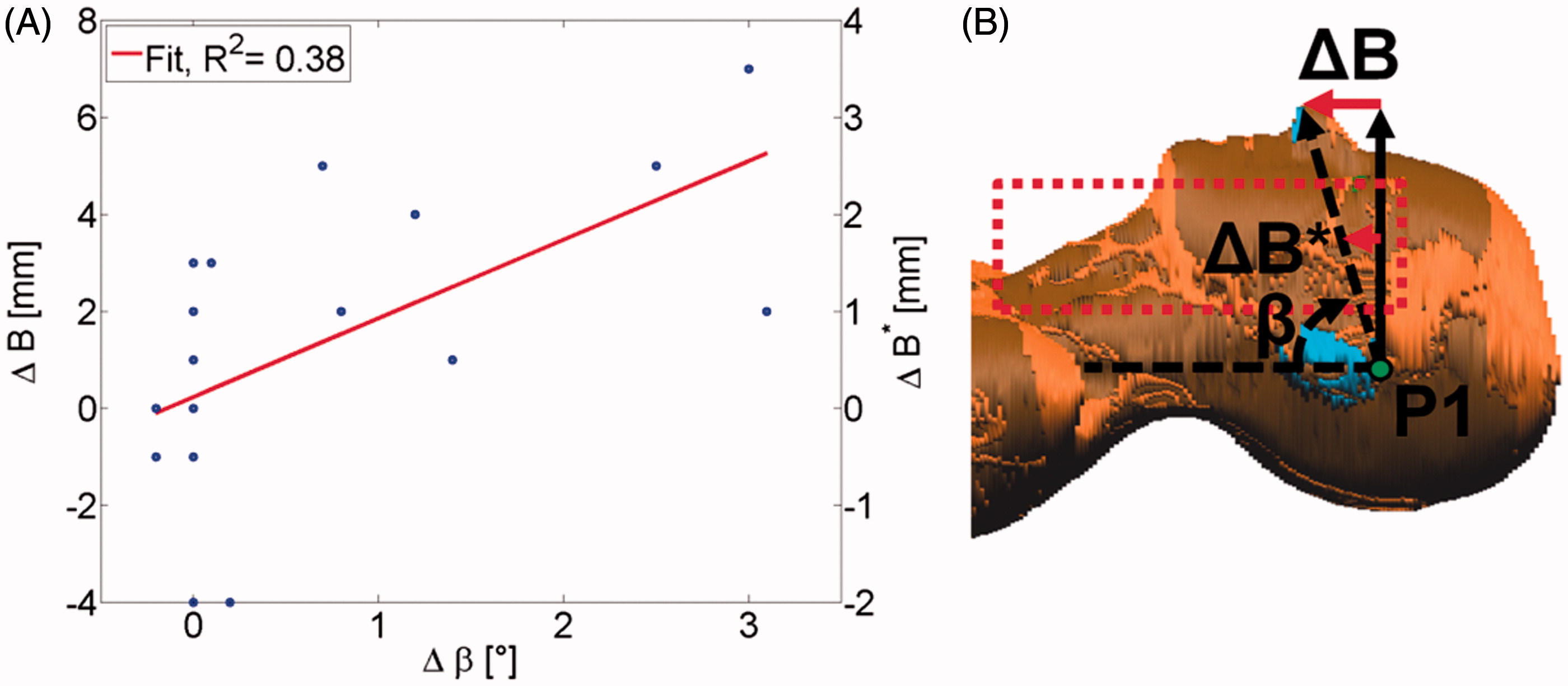
The test, using the redesigned applicator which was still under construction (), was carried out with five volunteers, for both α = 0° and α = 15°, and repeated twice. shows ΔA and ΔB. The range of ΔA is within −2 mm and 1 mm (median: 0 mm), while the range of ΔB is within −4 mm and 7 mm (median: 1 mm). shows a linear correlation (R2 = 0.38) between the angle Δβ and ΔB, and hence show that the higher ΔB values are caused by rotation of the patient, not by a shift. When there is no rotation, ΔB is between ±4 mm. The results of show that ΔA (Y-axis) have a larger influence on THQ than ΔB (Z-axis). Therefore, a low ΔA is more important than a low ΔB. Moreover, the effect of a large ΔB on THQ is even lower than predicts, because the higher ΔB values are caused by rotation, measured at the point of the nose. Since tumours are located closer to the rotational axis, often even within halfway, the shift of the target is twofold lower than the value of ΔB indicates, leading to the new parameter ΔB*, see . From the positioning test, it follows that the shift of the patient is within ±5 mm for both of the positioning parameters A and B, thus within the requirement devised from the positioning simulation study. In this test, the left–right positioning accuracy is not tested but we expect that the middle-sagittal laser line will effectively lead to a correct positioning of the left–right position of the patient.
Figure 7. The redesigned applicator under construction. The volunteer test was carried out early in the construction phase to allow for modifications if the new positioning procedure was inadequate.
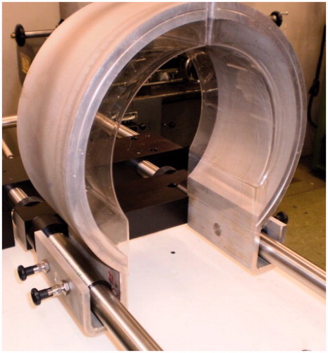
Figure 8. Results from the positioning test with volunteers, showing the difference between the position of the volunteer before and after the 5 min of lying in the redesigned applicator.
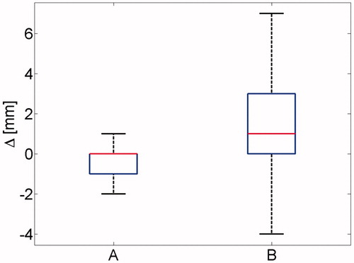
Figure 9. (A) Correlation of δβ and PB which shows that the largest values of δB are for the largest part caused by rotation of the patient (δβ) and not by a shift of the patient. (B) Explanation of δB*. Assume that the patient is rotated around the axis through P1, causing a shift in the measured B. The tumours of H&N patients are mostly located in the area indicated by the dotted rectangle. Because the target region is closer (roughly twice on average) to the point of rotation (P1) than the point of the nose where B is measured, we assume the shift of the tumours to be δB* = 1/2*δB.
Final applicator
In , an artistic impression of the novel applicator redesign is shown, including a redesign of the WB and a different positioning strategy. The main features are summarised below. An extensive overview of the improvements of the newly redesigned applicator over the old applicator can be found in . Note that the numbering corresponds to :
Instead of a cylinder, the redesign consists of two halves which can be closed after the patient is positioned (6).
A rigid outer WB, i.e. a separate antenna housing filled with circulated water, to allow stable antenna behaviour (6).
A flexible inner WB, composed from water-permeable foam, elastic foil and circulation tubing (1), which is exchangeable to allow head or neck treatments, respectively.
An adjustable HR (3), which enables fine-tuning of the head position and rotation, assisted by a sagittal laser set-up (5).
A positioning strategy which enables the patient to be positioned first, whereafter the applicator can be closed.
Table 1. Overview of the improvements of the newly redesigned applicator over the old applicator.
Discussion
This work shows that the WB shape can introduce a large error. By separating the WB into two parts, i.e. a rigid part and a flexible replaceable inner part, the flexible WB can be kept relatively thin for reducing the WB modelling errors. Moreover, the pre-shaped breathing gap in the inner WB and the fact that the inner WB nicely follows the patient contour will further diminish WB modelling errors. The experiments in this work showed that the problems with the current HYPERcollar WB will be solved: the WB nicely follows the patient contour, is not bulging out, and the cooling is uniform. Positioning was found important for a correct translation of HTP to the clinic, in agreement with [Citation19]. The new positioning strategy was shown to work well: the shift of the tumour (expressed in ΔA and ΔB*) was well within the requirements deduced from the simulation study. The volunteer test was carried out for 5 min, while an actual treatment lasts 75 min. However, since the WB is inflated, the patient is fixed with some pressure and therefore we expect an equal outcome for the longer duration of the test.
Togni et al. [Citation16] found that a new antenna arrangement will, on average, improve the THQ by 32% by lowering the relative hotspots. This result was obtained by implementing 20 antennas and selecting the 12 antennas that give, per Watt radiofrequency input-power, the highest SAR in the target region, which is needed to restrict the number of required applicators, and hence systems cost. Combined with the improvements in this work, we expect to enhance the achievable temperature even more than the new antenna arrangement alone, by an improved correlation between HTP and the clinic, making HTP-guided steering more effective.
The lower WB volume lowers the pressure on the patient, while the new positioning strategy allows for quicker patient positioning. The implementation of the breathing gap removes the need to make an artificial, unpredictable gap with sticky-tape as is currently done in HYPERcollar treatments. Moreover, the ability to open the two halves of the redesigned applicator makes the device more patient-friendly and operator-friendly. Patient comfort is an important factor in HT [Citation14]: if the patient feels comfortable, movement during treatment is less and increases the chance that the full treatment is completed.
Conclusions
The redesigned WB solves the major problems of the HYPERcollar WB: it improves the shape reproducibility and diminishes folds. Moreover, the lower amount of water volume improves the cooling capacity and lowers the pressure of the WB on the patient. Also, the renewed positioning strategy allows for quicker patient positioning, thereby increasing patient comfort. The new positioning strategy is able to position the patient within the required precision of ±5 mm. By clinically introducing the redesign, we expect that the quality of deep H&N HT treatments guided by simulations will improve, also leading to improved clinical outcome.
Declaration of interest
This study was supported by the Dutch Cancer Society (Grant DDHK2009-4270). The authors alone are responsible for the content and writing of the paper.
References
- Valdagni R. Two versus six hyperthermia treatments in combination with radical irradiation for fixed metastatic neck nodes: Progress report. Recent Results Cancer Res 1988;107:123–8
- Valdagni R, Amichetti M, Pani G. Radical radiation alone versus radical radiation plus microwave hyperthermia for N3 (TNM-UICC) neck nodes: A prospective randomized clinical trial. Int J Radiat Oncol Biol Phys 1988;15:13–24
- Valdagni R, Amichetti M. Report of long-term follow-up in a randomized trial comparing radiation therapy and radiation therapy plus hyperthermia to metastatic lymphnodes in stage IV head and neck patients. Int J Radiat Oncol Biol Phys 1994;28:163–9
- Amichetti M, Romano M, Busana L, Bolner A, Fellin G, Pani G, et al. Hyperfractionated radiation in combination with local hyperthermia in the treatment of advanced squamous cell carcinoma of the head and neck: A phase I–II study. Rad Oncol 1997;45:155–8
- Huilgol N, Gupta D, Sridhar C. Hyperthermia with radiation in the treatment of locally advanced head and neck cancer: A report of randomized trial. J Cancer Res Ther 2010;6:492–6
- Huilgol N, Gupta D, Dixit R. Chemoradiation with hyperthermia in the treatment of head and neck cancer. Int J Hyperthermia 2010;26:21–5
- Hua Y, Shenglin M, Zhenfu F, Qiaoying H, Wang L, Yongfeng P. Intracavity hyperthermia in nasopharyngeal cancer: A phase III clinical study. Int J Hyperthermia 2011;27:180–6
- Paulides MM. Towards developing effective hyperthermia treatment for tumours in the nasopharyngeal region. Int J Hyperthermia 2011;27:523–5
- Paulides MM, Bakker JF, Neufeld E, van der Zee J, Jansen PP, Levendag PC, et al. Winner of the ‘New Investigator Award’ at the European Society of Hyperthermia Oncology Meeting 2007. The HYPERcollar: A novel applicator for hyperthermia in the head and neck. Int J Hyperthermia 2007;23:567–76
- Neufeld E. High resolution hyperthermia treatment planning. Doctoral thesis, ETH Zurich, 2008
- Canters RAM, Paulides MM, Franckena MF, van der Zee J, van Rhoon GC. Implementation of treatment planning in the routine clinical procedure of regional hyperthermia treatment of cervical cancer: An overview and the Rotterdam experience. Int J Hyperthermia 2012;28:570–81
- Rijnen Z, Bakker JF, Canters RAM, Togni P, Verduijn GM, Levendag PC, et al. Clinical integration of software tool VEDO for adaptive and quantitative application of phased-array hyperthermia in the head and neck. Int J Hyperthermia 2013;29:181–93
- Paulides MM, Stauffer P, Neufeld E, Maccarini P, Kyriakou A, Canters RAM, et al. Simulation techniques in hyperthermia treatment planning. Int J Hyperthermia 2013;29:346–57
- Paulides MM, Bakker JF, Linthorst M, van der Zee J, Rijnen Z, Neufeld E, et al. The clinical feasibility of deep hyperthermia treatment in the head and neck: New challenges for positioning and temperature measurement. Phys Med Biol 2010;55:2465–80
- Paulides MM, Bakker JF, van Rhoon GC. Electromagnetic head-and-neck hyperthermia applicator: Experimental phantom verification and FDTD model. Int J Radiat Oncol Biol Phys 2007;68:612–20
- Togni P, Rijnen Z, Numan WCM, Verhaart RF, Bakker JF, Rhoon GC, et al. Electromagnetic redesign of the HYPERcollar applicator: Toward improved deep local head-and-neck hyperthermia. Phys Med Biol 2013;58:5997–6009
- Verhaart RF, Fortunati V, Verduijn GM, van Walsum T, Veenland JF, Paulides MM. CT-based patient modeling for head and neck hyperthermia treatment planning: Manual versus automatic normal-tissue-segmentation. Rad Oncol 2014;111:158–63
- Canters RAM, Franckena M, van der Zee J, Van Rhoon GC. Complaint-adaptive power density optimization as a tool for HTP-guided steering in deep hyperthermia treatment of pelvic tumors. Phys Med Biol 2008;53:6799–820
- Canters RAM, Franckena M, Paulides MM, Van Rhoon GC. Patient positioning in deep hyperthermia: Influences of inaccuracies, signal correction possibilities and optimization potential. Phys Med Biol 2009;54:3923–36
- Togni P, Roskam R, Rijnen Z, Paulides MM. HYPERcollar redesign: Towards improved head-and-neck hyperthermia treatment. Poster session presented at: 28th Annual Conference of the European Society for Hyperthermic Oncology 2013;Munich, Germany