Abstract
Introduction. Fiducial markers based on a removable stent are currently used in image guided radiotherapy. Here it is investigated what the possible dosimetric impact of such a marker could be, if used in proton or carbon ion treatment. Material and methods. The simulations have been done using the Monte Carlo particle transport code FLUKA with its default hadron therapy settings. A 3 cm long stent is approximated in FLUKA by stacking hollow tori. To simulate realistic clinical conditions a field 5 × 5 cm has been used, delivering a 5 cm wide spread out Bragg peak located 5 cm deep for protons and carbon ions. For protons fields mimicking active and passive beam delivery have been investigated. The stent has been arranged perpendicular, turned 45 degrees, and parallel to the beam axis. Results. The position of the 95% dose level shifts for carbon ions 7 mm in proximal direction for the marker perpendicular to the beam and 8 mm if the stent is turned 45 degree for a 1 × 1 cm dose binning on the centre beam axis. For the case where the stent was parallel to beam direction the 95% dose level shifts 26 mm. For active delivered protons, the shift of the 95% dose level is less. The shift for a perpendicular arranged marker is 6 mm, for 45 degrees turned it is 7 mm. For the case where the stent was oriented parallel to the beam, the observed shift is 21 mm. Dose inhomogeneities caused by straggling effects occur only near the distal edge of the field. Conclusions. The results of our investigations show that the Ni-Ti marker has a non negligible impact on the dose distributions for the used radiation types. However if the treatment plan rules out narrow angles between symmetry axis of the stent and the beam direction, this may be compensated.
Radiotherapy has become a standard procedure in the treatment of prostate cancer, and recent studies show still increasing local control rates at doses above 75–80 Gy [Citation1]. Due to the very high target doses used and the vicinity of prostate to radio sensitive normal tissue, primarily the rectal wall, high geometrical accuracy of the dose delivery is required to assure target coverage as well as optimal normal tissue sparing. In external x-ray radiotherapy daily image-guidance, using orthogonal kV or MV images or cone beam CT, combined with radiopaque fiducial markers in prostate is widely applied. Studies of various fiducial systems have shown improved geometrical accuracy compared to setups with bony anatomy or external skin markers [Citation2]. The most commonly used material for the radiopaque fiducial markers is gold, but other high Z materials like silver and steel are also used. For particle therapy the use of fiducial markers is not straightforward. The high Z materials create artefacts on the CT-scan used for treatment planning challenge the dose calculation algorithms [Citation3] and perturb the particle radiation field [Citation4], if the beam passes through the marker (which can not always be avoided) this may cause severe under-dosage in the region behind the marker.
The daily alignment of a patient by using metallic markers may not be appropriate for heavy charged particles, because the particle range depends also on the alignment of traversed tissue (especially bony structures). As long as volumetric kV-imaging is not easily available in the treatment room, metallic markers will be used for patient setup as well as for tracking organ motion, as it is currently done, e.g. for lung tumours [Citation5].
The reduced particle range behind the markers could be handled by additional margins, but alternative methods should be investigated. Alternative fiducial markers, e.g. based on microscopic gold particles have been suggested [Citation6]. A novel developed stent marker based on nickel and titanium has been clinically tested for conventional x-ray radiotherapy [Citation7]. Ni and Ti have lower atomic numbers than the traditionally used markers suggesting the hypothesis that for the Ni-Ti stent the above mentioned problems will be less pronounced. In fact, the stent shows less artefacts on CT images than, e.g. gold markers, but partial volume effects make the stent appear larger on CT than the actual physical dimensions [Citation7]. Contrary to smaller Ti markers the stent is easily identifiable on radiographic images [Citation8]. Another advantage of this given marker is that it is possible to place and remove it without surgery. This study addresses the perturbation of the radiation field by the Ni-Ti stent which may arise from the fine structure of the stent in contrast to its total size.
Material and methods
The marker we investigated is a stent consisting of a hollow tube formed as a spiral, made of a Ni-Ti alloy. It is different from the one used in the aforementioned studies [Citation7,Citation8] since they used one made of solid wire. The tube has an outer diameter of 0.6 mm and an inner diameter of 0.35 mm. The spiral has a diameter of 7 mm and is available in different lengths. The single layers of the spiral are in contact, so that no tissue can grow between two layers and complicate the removal of the stent.
Simulations have been done using the Monte Carlo particle transport code FLUKA [Citation9], which is benchmarked for therapeutic carbon ion beams [Citation10] and also used for protons in clinical settings [Citation11]. The default hadron therapy settings, including the DPMJET3 [Citation12] fragmentation model, have been used.
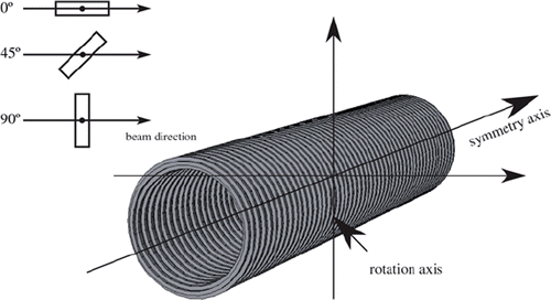
The geometry of the stent has been carefully implemented. We have chosen a stent length of 3 cm. Its centre was placed in 7.5 cm water depth. To estimate the impact of the angle of the stent towards the beam it has been arranged with its symmetry axis in beam direction, perpendicular and with an angle of 45 degree to the beam direction (see ).
The treatment planning code for particle therapy TRiP [Citation13] was used for planning a single carbon ion 5 × 5 × 5 cm3 cube shaped PTV, centred at 7.5 cm water depth. Raster scanning was assumed, where individual scan points were fluence weighted. For protons we used two different field designs. One, similar to the carbon field, designed with TRiP mimicking spot scanning, and another field which mimics a field generated with a passive system and hence a high angular divergence, we have chosen a value of 38 mrad.
The accelerator control files generated by TRiP were imported into FLUKA. Here straggling effects from metal artefacts is better handled since FLUKA is a full Monte Carlo particle transport system.
In order to estimate the dosimetrical influence we scored a depth dose curve along the beam direction through the stent. Three different box-shaped scoring volumes were applied: 0.5 × 0.5 × 12 cm3, 1 × 1 × 12 cm3 and 2 × 2 × 12 cm3. The scoring volume was divided in 0.1 mm bins along the beam axis. In addition we scored the dose in high resolution around the stent in order to identify eventual over or under dosage regions.
Results
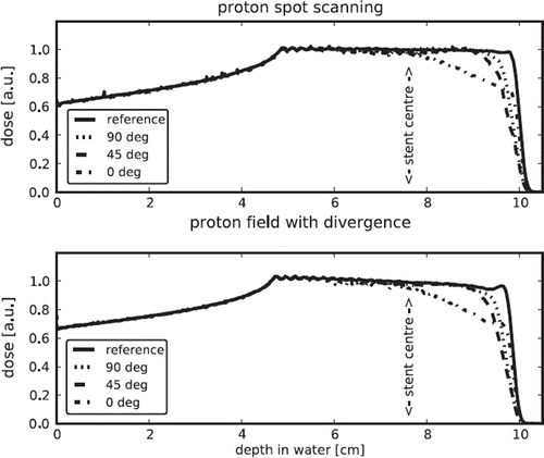
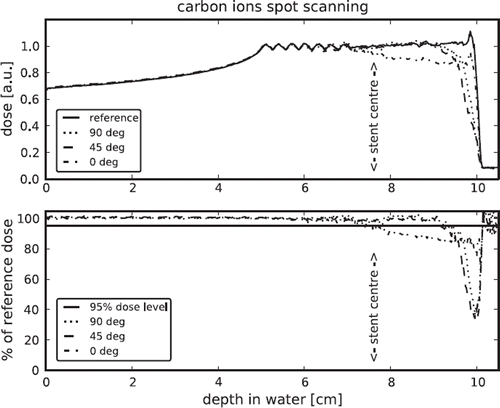
The and show the depth dose curves for the given settings and bins of size 1.0 × 1.0 × 0.1 cm3. The upper part of shows the depth dose curves for the reference field, without a stent, and the curves for geometries including the stent with the respectively angle. The lower part shows the ratio between the dose distribution for the different setups and the reference, the 95% level is indicated. shows the depth dose curves for protons delivered with active and passive beam delivery.
Figure 3. Depth dose curves for proton fields delivered with raster scanning and with high divergence.

Additional the position of the rotation centre (see ) of the stent is indicated. The range reduction regarding the 95% dose level and the dose levels of the maximum dose falloff are summarised in .
Table I. Summary of the range reduction of the 95% dose level and the dose level of maximum dose falloff compared to reference field for the different settings.
Discussion
The size of the dose scoring volume influences the results, depending of the stent arrangement. In order to be able to compare depth dose curves for all three stent orientations, we chose the scoring area of 1 cm × 1 cm since this is wider than the stent diameter but does not average over a too wide area as the 2 cm × 2 cm scoring does. Scoring areas smaller than the inner diameter of the stent (5.8 mm) would make the depth dose curves incomparable, since there would be no stent material in the examined area for the orientation in beam direction (0°), but for the other orientations.
For carbon ions as for protons, in both settings, the dose shadow behind the stent is reduced when the stent is under 90° to the beam axis and highest if the stent is in beam direction. The setup with an angle of 45° results in a just slightly different dose distribution in comparison with the setup perpendicular to beam direction.
Both ion types show similar behaviour, the main difference is the minor dose falloff for a stent in beam direction for carbon ions compared with protons. This can be explained by less scattering of carbon ions compared to protons, hence more carbon ions can pass the “tunnel” formed by the stent in beam direction.
For protons there is a difference in the dosimetric impact of the stent on an active raster scanning and a passive field with high angular divergence for the stent in beam direction. The range shift is less for the scanned field with less divergence and hence less scattered particles in the stent.
An important aspect is, whether the dosimetric impact of the stents is important for radiotherapy. Since it is very unlikely, that the stents are aligned precisely along the beam axis, the dosimetric effects are probably relatively minor. Even if the stents are used to re-align the patient in daily setup, there will probably be small rotations of the stents around the isocentre, so that some amount of averaging of the cold spots is to be expected. The size of the resulting effects in a fractionated therapy can thus only be estimated by sampling the remaining rotational errors in daily setup.
Conclusion
The results of our investigations show that the Ni-Ti marker has a non negligible impact on the dose distributions for the used radiation types. The results show furthermore that the orientation towards the incoming beam has, as expected, a large influence on the dose shadow. Interestingly, the range reduction for a stent in beam direction may be larger, but the maximal dose falloff is less than for other orientations, and also that the difference between fields with low and with high divergence is quite low.
Several concerns should be made if treating prostate cancer with particles and using the Ni-Ti stent as fiducial marker for beam alignment. Beams entering through the perineum as used for proton therapy some places [Citation14] should be avoided, while coaxial beams would be acceptable if the reduced range is included in the treatment margin calculation. Using a larger number of beams could reduce the necessity for large margin extensions.
Acknowledgements
The Danish Cancer Society supported this work with a grant. CIRRO – The Lundbeck Foundation Center for Interventional Research in Radiation Oncology and The Danish Council for Strategic Research are also acknowledged for their financial support.
Declaration of interest: The authors report no conflicts of interest. The authors alone are responsible for the content and writing of the paper.
References
- Kuban DA, Tucker SL, Dong L, Starkschall G, Huang EH, Cheung MR, . Long-term results of the M. D. Anderson randomized dose-escalation trial for prostate cancer. Int J Radiat Biol Phys 2008;70:67–74.
- Poulsen PR, Muren LP, Høyer M. Residual set-up errors and margins in on-line image-guided prostate localization in radiotherapy. Radiother Oncol 2007;85:201–6.
- Jäkel O, Reiss P. The influence of metal artefacts on the range of ion beams. Phys Med Biol 2007;52:635–44.
- Newhauser W, Fontenot J, Koch N, Dong L, Lee A, Zheng Y, . Monte Carlo simulations of the dosimetric impact of radiopaque fiducial markers for proton radiotherapy of the prostate. Phys Med Biol 2007;52:2937–52.
- Miyamoto T, Yamamoto N, Nishimaura H, Koto M, Tsuji H, Mizoe J, . Carbon ion radiotherapy for stage I non-small cell lung cancer. Radiother Oncol 2002;66:127–40.
- Lim YK, Kwak J, Kim DW, Shin D, Yoon M, Park S, . Microscopic gold particle-based fiducial markers for proton therapy of prostate cancer. Int J Radiat Oncol Biol Phys 2009;74:1609–16.
- Carl J, Nielsen J, Holmberg M, Larsen EH, Fabrin K, Fisker RV. A new fiducial marker for image-guided radiotherapy of prostate cancer: Clinical experience. Acta Oncol 2008;47: 1358–66.
- Carl J, Lund B, Larsen EH, Nielsen J. Feasibility study using a Ni-Ti stent and electronic portal imaging to localize the prostate during radiotherapy. Radiother Oncol 2006;78: 199–206.
- Battistoni G, Muraro S, Sala PR, Cerutti F, Ferrari A, Roesler S, . FLUKA: A multi-particle transport code. Albrow M, Raja R. Proceedings of the Hadronic Shower Simulation Workshop, Fermilab; 2006 Sep 6–8. AIP Conference Proceeding 2007;896:31–49.
- Sommerer F, Parodi K, Ferrari A, Poljanc K, Enghardt W, Aiginger H. Investigating the accuracy of the FLUKA code for transport of therapeutic ion beams in matter. Phys Med Biol 2006;51:4385–98.
- Parodi K, Enghardt W, Haberer T. In-beam PET measurements of β+ radioactivity induced by proton beams. Phys Med Biol 2002;47:21–36.
- Roesler S, Engel R, Ranft J. The Monte Carlo event generator DPMJET-III. Kling A, Barao F, Nakagawa M, Tavora L, Vaz P. Proceedings Monte Carlo 2000 Conference; 2000 Oct 23–26; Lisbon. Berlin: Springer-Verlag; 2001. 1033–8.
- Krämer M, Jäkel O, Haberer T, Kraft G, Schardt D, Weber U. Treatment planning for heavy-ion radiotherapy: Physical beam model and dose optimization. Phys Med Biol 2000;45: 3299–317.
- Isacsson U, Nilsson K, Asplund S, Morhed E, Montelius A, Turesson I. A method to separate the rectum from the prostate during proton beam radiotherapy of prostate cancer patients. Acta Oncol 2010;49:500–5.


