Abstract
Background. Magnetic resonance imaging (MRI) instrumentation is vulnerable to technical and image quality problems, and quality assurance is essential. In the studied regional imaging center the long-term quality assurance has been based on MagNET phantom measurements. American College of Radiology (ACR) has an accreditation program including a standardized image quality measurement protocol and phantom. The ACR protocol includes recommended acceptance criteria for clinical sequences and thus provides possibility to assess the clinical relevance of quality assurance. The purpose of this study was to test the ACR MRI phantom in quality assurance of a multi-unit imaging center. Material and methods. The imaging center operates 11 MRI systems of three major manufacturers with field strengths of 3.0 T, 1.5 T and 1.0 T. Images of the ACR phantom were acquired using a head coil following the ACR scanning instructions. Both ACR T1- and T2-weighted sequences as well as T1- and T2-weighted brain sequences in clinical use at each site were acquired. Measurements were performed twice. The images were analyzed and the results were compared with the ACR acceptance levels. Results. The acquisition procedure with the ACR phantom was faster than with the MagNET phantoms. On the first and second measurement rounds 91% and 73% of the systems passed the ACR test. Measured slice thickness accuracies were not within the acceptance limits in site T2 sequences. Differences in the high contrast spatial resolution between the ACR and the site sequences were observed. In 3.0 T systems the image intensity uniformity was slightly lower than the ACR acceptance limit. Conclusion. The ACR method was feasible in quality assurance of a multi-unit imaging center and the ACR protocol could replace the MagNET phantom tests. An automatic analysis of the images will further improve cost-effectiveness and objectiveness of the ACR protocol.
The complex nature and high accuracy demands of magnetic resonance imaging (MRI) instrumentation makes it vulnerable to technical and image quality problems. Although the question of appropriate technical quality assurance of MRI has not triggered as many national and international guidelines as the imaging methods using ionizing radiation, substantial work has been done. The Eurospin project in the 1990s recommended a set of standard phantoms [Citation1]. The MagNET phantoms have been used in the evaluation program supported by the UK Government's Centre for Evidence-based Purchasing [Citation2]. American Association of Physicists in Medicine (AAPM) published its quality assurance recommendation in 1990 [Citation3]. There are also international standards for image quality measurement [Citation4–8]. American College of Radiology (ACR) has its own phantom for accreditation purposes [Citation9]. Several research groups have also suggested quality assurance protocols [Citation10–15].
Large healthcare providers often have several MRI systems on several sites, possibly including mobile units. The sites typically use a common picture archiving and communications system, and the images are not necessarily read on the site where the imaging itself takes place. The technical and clinical quality of the images from different sites should fulfill the same standards when the indication for the imaging is the same. Therefore uniform and consistent technical quality assurance is essential. The MRI quality assurance protocol of our multi-unit imaging center currently consists of three parts: 1) Daily single-slice spin-echo image of a manufacturer-specific homogenous phantom, 2) coil tests performed using manufacturer-specific phantoms and instructions, and 3) annual measurement of MagNET phantoms [Citation2]. This protocol has been used for several years and questions have arisen regarding the optimal time interval between different tests. Some measurements are time consuming and their clinical relevance has been discussed, since the sequences differ from those used in clinical practice. Thus new methods are continuously evaluated.
American College of Radiology (ACR) has built an accreditation program for the U.S. MRI sites [Citation9]. The program includes measurements with a standardized phantom to estimate the technical quality of images. The phantom is also available for centers not taking part in the accreditation program. The phantom includes features that enable versatile image quality measurement and evaluation. An important advantage compared to our current quality assurance measurements is that the ACR protocol also recommends image quality acceptance levels for MRI sequences used in clinical practice.
The objectives of this study were to test the feasibility of quality assurance with the ACR MRI accreditation phantom in our organization and to explore the possibility to replace some of the existing quality assurance procedures with the ACR phantom test. The ACR method was selected for evaluation because of its internationally recognized position, as well as the short measurement time of the protocol.
Material and methods
The ACR MRI accreditation phantom is cylindrical and has an inside diameter of 190 mm and an inside length of 148 mm. It is filled with 10 mM NiCl2 and 75 mM NaCl. It contains structures for measuring geometric accuracy, high-contrast spatial resolution, slice thickness accuracy, slice position accuracy, image intensity uniformity, percent signal ghosting and low-contrast detectability. The phantom images were acquired on 11 MRI systems of three major manufacturers following the ACR site scanning instructions [Citation16]. The field strengths were 3.0 T (systems #1 and #2), 1.5 T (systems #3 to #10) and 1.0 T (system #11). All the systems were administered and operated by one regional imaging center. Apart from system #11, all the systems had been purchased or upgraded during the last seven years. The MRI systems were located in eight different hospital buildings and in a mobile unit (system #10). The clinically used head coil of each system was used in the measurements, with the exception of system #10 as the phantom was too large to fit inside that particular coil. The coils were 8- or 12-channel coils, apart from single channel coils on systems #6, #10 and #11. The phantom was carefully leveled inside the coil, and the center point of the phantom was aligned with the center point of the coil and the isocenter of the magnet with the positioning lasers. The anatomically shaped design of some coils prevented positioning of the phantom at the center of the coil. The measurement was performed twice on each system. The time interval between the two measurements varied from three to nine months.
According to the measurement protocol, a sagittal slice (locator) was acquired first. Then, axial sequences defined by the ACR and each site's own T1- and T2-weighted head sequences were acquired. In many cases the site sequences needed to be selected among several possible sequences used at the respective site. Number of slices, slice gap and slice thickness of the site sequences were determined by the ACR protocol, to ensure acquisition of the slices in correct positions for analysis. The sequence parameters are listed in . Pixel sizes for and were calculated by dividing the field of view by the acquisition matrix. Image intensity correction options of multi-element coils were turned on in the ACR sequences whenever they were routinely used in clinical head sequences of the respective site, absent only on system #9. Parallel imaging was used in site T2 sequence of systems #2, #7 and #8.
Table I. Imaging parameters of the ACR sequences [Citation16].
Table II. Imaging parameters of site T1-weighted sequences of different systems.
Table III. Imaging parameters of site T2-weighted sequences of different systems.
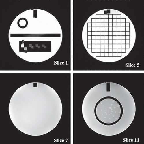
The images (examples in ) were analyzed according to the ACR instructions by the same single observer and the results were compared to the ACR specifications [Citation17]. Geometric accuracy was evaluated by measuring seven known distances in the images. High-contrast spatial resolution was assessed visually based on the distinguishability of hole-array pairs with hole diameters of 0.9 mm, 1.0 mm and 1.1mm. Slice thickness was calculated from the known ramp angle and slice position accuracy measurement was based on wedge visualization. Image intensity uniformity was calculated from pixel values inside a region of interest in a slice containing only uniform material. Ghosting values were calculated from regions of interest placed outside the phantom in the image. Low-contrast object detectability was visually assessed by calculating number of objects visible in four images with gradually decreasing contrast and object size.
Figure 1. Examples of ACR phantom images. In slice 1 the hole-array pairs are used for high-contrast spatial resolution and the ramps in the middle for slice thickness accuracy. Slice 5 together with measurements from slice 1 and the sagittal image are used for the geometric accuracy determination. Image intensity uniformity is determined from slice 7 and slices 8 to 11 are used for low-contrast object detectability measurement.

Results
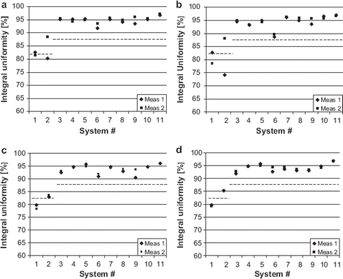
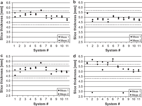
Results of the seven evaluated parameters are presented in and and . The measured image intensity percent integral uniformities are shown in . The ACR recommended acceptance values are 82% for 3.0 T and 87.5% for 1.5 T. Image uniformity was slightly below this value on both 3.0 T systems. In the measured image slice thicknesses are compared to ACR recommended acceptance limits of ± 0.7 mm. The results were outside the limits more often in the site T2-weighted sequences than in the other sequences. The mean observed slice thickness was 4.9 mm in ACR T2 sequences and 5.3 mm in site T2 sequences.
Figure 2. Image intensity percent integral uniformity of a. ACR T1, b. ACR T2, c. site T1 and d. site T2 sequences. The dash lines indicate the ACR recommended acceptance values for 1.5 T (87.5%) and 3.0 T (82%).

Figure 3. Slice thickness accuracy; the nominal value is 5 mm with ±0.7 mm tolerance, limits indicated by dash lines. a. ACR T1, b. ACR T2, c. site T1 and d. site T2 sequences.

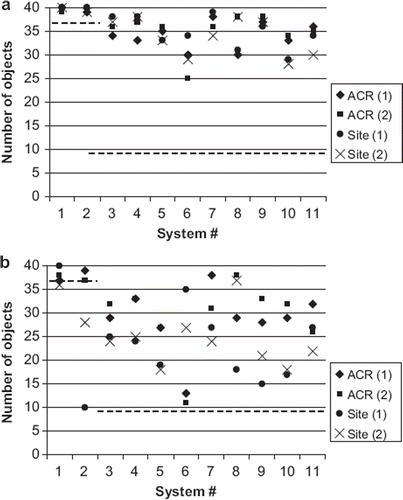
Figure 4. Low contrast detectability of measurements 1 and 2 for a. T1-weighted sequences and b. T2-weighted sequences. The dash lines indicate the ACR recommended acceptance values for 1.5 T (9 objects) and 3.0 T (37 objects).

Table IV. High contrast spatial resolution of site sequences.
Table V. Percentages of the systems that passed the ACR recommended acceptance criteria in each test.
The systems achieved high-contrast spatial resolution corresponding to the acquired pixel size of 1.0 × 1.0 mm with the ACR sequences. This was also the ACR recommended acceptance value. The measured high contrast spatial resolution was generally lower for site T1-weighted sequences and higher for site T2-weighted sequences, when comparing with the respective ACR sequences (). There were differences also between anterior-to-posterior and left-to-right direction in some images. Low-contrast detectability results are shown in . All the systems passed the ACR determined criteria, which was nine objects for 1.5 T and 37 objects for 3.0 T systems. The mean number of visible objects was 34 and standard deviation was 3.6 in the T1 sequences of the 1.5 T systems. There was larger variation in the T2 sequences, both between systems, ACR and site sequences, and different measurements of the same system; the mean number of visible objects was 26 and standard deviation was 7.3 in 1.5 T systems. All results of percent signal ghosting and slice positioning accuracy were within the ACR recommended acceptance criteria. In ghosting the criterion is 0.025% and the majority of the results were under 0.01%. In slice positioning accuracy the recommended acceptance criterion is ±5 mm. The measured deviations were between 0 mm and 3.6 mm. Generally the systems also passed the geometric accuracy test with limits of ±2 mm when measuring a known length of 190 mm, but two systems failed the test in one measurement.
lists the results of passing or failing of each test in relation to the ACR recommended acceptance criteria. The tests that failed most commonly were high-contrast spatial resolution and slice thickness accuracy. The tests passed more often with the ACR sequences than the site sequences. The ACR instructions define that the overall test is passed if the criteria are met either with the ACR or the site sequences. The overall passing rate was 91% in the first and 73% in the second measurement.
Discussion
Despite well-designed manufacturer-specific service programs, it is essential to use standard phantoms in MRI quality assurance to enable uniform measurement of the systems in a multi-unit imaging center. In this study 11 MRI systems of a regional imaging center were measured twice with the ACR phantom to evaluate the feasibility of the ACR test for quality assurance of a large organization. Generally the ACR protocol was easy to perform and clearly instructed. The results showed that most of the systems operated at the level fulfilling the ACR recommended acceptance criteria. These observations were in agreement with another study by Chen et al. using the same phantom [Citation15]. There were, however, some difficulties in applying the protocol into practice. The phantom did not fit inside all head coils. This was the case with system #10, but also with the 32-channel coil of system #2. The field-of-view was not allowed to be adjusted in site sequences, although in some cases it was too small to allow measurements of ghosting and geometric accuracy. The slice thickness results may have been affected by poor visibility of ramps in the phantom image with some T2-weighted sequences. In addition, there are acquisition parameters that are not defined for the ACR sequences. These include the receiver bandwidth, signal intensity correction methods and reconstruction filters. The choice of these parameters may have affected the results of low contrast detectability and image uniformity in this study. Pixel size differences and possible interpolation in reconstruction in clinical sequences had an effect on the results of the high contrast spatial resolution. Factors related to coil structure and B1 field may explain the performance of 3.0 T systems in the uniformity test.
The possibility to replace some of the existing quality assurance methods with the ACR method in our center was one of the objectives of the study. Currently a simple quality assurance test is performed with a homogenous phantom for the head coil every morning immediately after start-up of the system. Obvious faults with the system can be detected before the first patient of the day has been positioned on the scanner table. Due to well defined practice it is not relevant to replace the daily procedure with the ACR phantom test. The manufacturer specified coil tests cannot obviously be replaced either. However, the MagNET and the ACR phantom tests are both manufacturer independent and could therefore be interchangeable. The parameters measured by both methods are essentially the same. The ACR phantom test does not include a pure signal-to-noise ratio measurement and MagNET phantoms do not include structures for low-contrast detectability assessment. However, the signal-to noise ratio has a direct effect on the low contrast detectability. The advantages of the ACR phantom test compared to MagNET phantom tests are 1) fast acquisition of images (20 min), 2) inclusion of clinical sequences in the measurement protocol and 3) globally more recognized method. The reasons that speak for continuing with MagNET phantoms are 1) long measurement history in our organization, 2) measurement of three orthogonal slice planes and 3) in-house developed automatic analysis software that makes the image analysis fast and objective. One limitation of this study was that thus far only two measurements have been performed with the ACR phantom. Before final conclusion whether the ACR method has the potential to reveal changes in the performance of the systems better than the MagNET method, longer term follow-up of the ACR phantom measurements would be needed.
Both the measurement and the analysis should be reasonably fast to meet the demands of cost-effectiveness. In our organization the analysis of MagNET phantom images is automated which has made the analysis considerably faster and more objective. Developing automatic analysis software for the ACR phantom test would increase its cost-effectiveness and objectivity as well. The need for increased objectivity in the ACR image analysis is most obvious in slice thickness and low contrast object detectability measurements. The increasing role of anatomical and functional MRI in diagnosis, treatment planning and follow-up of cancer patients sets demands for objectivity and repeatability of quality assurance methods [Citation18,Citation19].
As Weinreb et al. [Citation9] pointed out, clinical relevance of quality assurance is difficult to evaluate. In most quality assurance protocols the tests are performed with spin-echo sequences, which usually differ from the clinical sequences [Citation1,Citation2]. Connecting the quality assurance test to clinical image quality by using the same sequences is an advantage of the ACR method. It should also be noted, that the phantoms available for MRI quality assurance do not provide complete methods to evaluate clinical image quality. For example, none of the quality assurance protocols used or discussed in this study provides means to assess effectiveness of fat suppression, which is essential in clinical imaging. Even more important, the vast variety of contrasts in clinical images can not be mimicked by the current phantoms. The most challenging methods, such as functional MRI, diffusion and perfusion are pushing the systems to their limits and need dedicated quality assurance procedures [Citation11].
Different sites of a multi-unit imaging center often have adopted their own conventions in imaging, even when the indication for imaging is the same. Still the minimum image quality level should be equal in all the sites. In practice the patient material varies from site to site and technical properties of the MRI systems may limit the achievable image quality. Clinical audit practices in the European Union have helped in approaching the objective of equal image quality with imaging methods using ionizing radiation, and there are recommendations and criteria to systematically evaluate clinical image quality from patient images [Citation20,Citation21]. Same kind of approach could be justifiable in MRI as well, and, for example the ACR accreditation program includes evaluation of clinical patient images in addition to phantom images. One possible future direction of this study would be to extend the quality assurance protocol by connecting the phantom results with the quality of patient images.
In conclusion, the ACR method proved feasible for quality assurance in a multi-unit imaging center and the ACR protocol could replace the MagNET phantom tests. The image acquisition procedure of the ACR test was fast and practical. Automatic analysis of the images will further improve cost effectiveness and objectiveness of the ACR protocol.
Declaration of interest: The authors report no conflicts of interest. The authors alone are responsible for the content and writing of the paper.
References
- Lerski RA, de Certaines JD. Performance assessment and quality control in MRI by Eurospin test objects and protocols. Magn Reson Imaging 1993;11:817–33.
- DeWilde J, Price D, Curran J, Williams J, Kitney R. Standardization of performance evaluation in MRI: 13 years’ experience of intersystem comparison. Concepts Magn Reson Part B Magn Reson Eng 2002;15:111–6.
- Price RR, Axel L, Morgan T, Newman R, Perman W, Schneiders N, . Quality assurance methods and phantoms for magnetic resonance imaging: Report of AAPM nuclear magnetic resonance Task Group No. 1. Med Phys 1990;17:287–95.
- National Electrical Manufacturers Association. NEMA Standards Publications MS 1-2008, Determination of Signal-to-Noise Ratio (SNR) in Diagnostic Magnetic Resonance Imaging. Rosslyn (VA), USA; 2008.
- National Electrical Manufacturers Association. NEMA Standards Publications MS 2-2008, Determination of Two-Dimensional Geometric Distortion in Diagnostic Magnetic Resonance Images. Rosslyn (VA), USA; 2008.
- National Electrical Manufacturers Association. NEMA Standards Publications MS 3-2008, Determination of Image Uniformity in Diagnostic Magnetic Resonance Images. Rosslyn (VA), USA; 2008.
- National Electrical Manufacturers Association. NEMA Standards Publications MS 5-2003, Determination of Slice Thickness in Diagnostic Magnetic Resonance Imaging. Rosslyn (VA), USA; 2003.
- International Electrotechnical Commission. International standard 62464-1, Magnetic resonance equipment for medical imaging – Part 1: Determination of essential image quality parameters. Geneva, Switzerland; 2007.
- Weinreb J, Wilcox PA, Hayden J, Lewis R, Froelich J. ACR MRI Accreditation: Yesterday, today, and tomorrow. J Am Coll Radiol 2005;2:494–503.
- Firbank MJ, Harrison RM, Williams ED, Coulthard A. Quality assurance for MRI: Practical experience. Br J Radiol 2000;73(868):376–83.
- Friedman L, Glover GH. Report on a multicenter fMRI quality assurance protocol. J Magn Reson Imaging 2006;23: 827–39.
- Gunter JL, Bernstein MA, Borowski BJ, Ward CP, Britson PJ, Felmlee JP, . Measurement of MRI scanner performance with the ADNI phantom. Med Phys 2009;36:2193–205.
- Ihalainen T, Sipilä O, Savolainen S. MRI quality control: Six imagers studied using 11 unified image quality parameters. Eur Radiol 2004;14:1859–65.
- Mulkern RV, Forbes P, Dewey K, Osganian S, Clark M, Wong S, . Establishment and results of a magnetic resonance quality assurance program for the Pediatric Brain Tumor Consortium. Acad Radiol 2008;15:1099–110.
- Chen CC, Wan YL, Wai YY, Liu HL. Quality assurance of clinical MRI scanners using ACR MRI phantom: Preliminary results. J Digit Imaging 2004;17:279–84.
- The American College of Radiology. Site scanning instructions for use of the MR phantom for the ACR MRI accreditation program. Reston (VA), USA; 2004.
- The American College of Radiology. Phantom test guidance for the ACR MRI accreditation program. Reston (VA), USA; 2005.
- Buhl SK, Duun-Christensen AK, Kristensen BH, Behrens CF. Clinical evaluation of 3D/3D MRI-CBCT automatching on brain tumors for online patient setup verification – A step towards MRI-based treatment planning. Acta Oncol 2010;49:1085–91.
- Partridge M, Yamamoto T, Grau C, Høyer M, Muren LP. Imaging of normal lung, liver and parotid gland function for radiotherapy. Acta Oncol 2010;49:997–1011.
- European Commission. Radiation Protection No. 159. European Commission guidelines on clinical audit for medical radiological practices (diagnostic radiology, nuclear medicine and radiotherapy). Luxembourg: Publications Office of the European Union; 2009.
- European Commission. European guidelines on quality criteria for diagnostic radiographic images. Report EUR 16260 EN. Luxembourg; Office for official publications of the European Communities; 1996.
