Abstract
Objective: Movements of brain tissue during neurosurgical procedures reduce the effectiveness of using pre-operative images for intra-operative surgical guidance. In this paper, we explore the use of acquiring intra-operative ultrasound (US) images for the quantification of and correction for non-linear brain deformations.
Materials and Methods: We will present a multi-modal registration strategy that automatically matches pre-operative images (e.g., MRI) to intra-operative US to correct for these deformations. The strategy involves using the predicted appearance of neuroanatomical structures in US images to build “pseudo ultrasound” images based on pre-operative segmented MRI. These images can then be non-linearly registered to intra-operative US using cross-correlation measurements within the ANIMAL package. The feasibility of the theory is demonstrated through its application to clinical patient data acquired during 12 neurosurgical procedures.
Results: Results of applying the method to 12 surgical cases, including those with brain tumors and selective amygdalo-hippocampectomies, indicate that our strategy significantly recovers from non-linear brain deformations occurring during surgery. Quantitative results at tumor boundaries indicate up to 87% correction for brain shift.
Conclusions: Qualitative and quantitative examination of the results indicate that the system is able to correct for non-linear brain deformations in clinical patient data.
Introduction
The precise localization of anatomical structures and pathological features within the complex three-dimensional (3D) architecture of the brain is one of the major challenges of neurosurgery. Image-guided neurosurgical (IGNS) systems that embed neuronavigation are becoming widely used for intra-cranial procedures Citation[1], Citation[2]. There are numerous benefits reported from the increased usage of IGNS. These include (i) minimally invasive cranial openings, (ii) accurate localization of sub-cortical lesions, (iii) reduction in blood loss, (iv) reduction in surgical time, and (v) a decrease in the complication rate and thus in intensive care unit and hospital stays Citation[3], Citation[4]. However, the requirements for a precise, reliable and accurate surgical guidance system are that the system error be low and that there exist a high rate of correlation between the pre-operative images and the surgical anatomy. Errors in IGNS caused by geometrical distortions in the pre-operative images, patient-to-image registration errors, and errors in tracking the surgical instruments are well-defined for various systems in existence Citation[2], Citation[5]. However, another important source of error is the deformation of the brain tissue from the time of pre-operative image acquisition to the time of the surgical procedure and, more importantly, during the surgery (i.e., the so-called “brain shift” phenomenon). Brain deformation is a complex, spatio-temporal phenomenon with a wide variety of causes, including both chemical and physical factors Citation[2], Citation[5–7]. IGNS systems based on pre-operative data alone cannot properly account for this type of deformation, which is estimated to range from 5 mm to 20 mm Citation[3], Citation[6].
To quantify and correct for spatial errors resulting from intra-operative brain deformations, registration strategies based on intra-operative MRI have been proposed and implemented Citation[8–10]. This approach has several strengths and weaknesses. Among the advantages are safer tumor resections, a better assessment of the resections, the quantification and visualization of brain deformations, and the detection of intra-operative complications such as hemorrhage. Nevertheless, a number of technical and logistical problems still exist. These include the surgeon's restricted access to the patient due to the confining layout of the MR system, the requirement for specialized operating rooms, the shortage of MR-compatible auxiliary equipment and surgical instruments, and the inconsistency of the resulting image quality. Finally, the significant expense of the solution, in terms of both acquisition equipment and MRI-friendly surgical tools, leads to questions regarding its cost-effectiveness Citation[9].
Another recently proposed approach for the correction of deformations consists of using pre-operative MR images to generate a 3D patient-specific model of the brain resulting from simulated surgical procedures Citation[11–14]. Since the causes of brain deformations are complex, predicting the physical and chemical processes that may be encountered in each case would be difficult. Moreover, the presence of pathologies increases the complexity of the processes, particularly in cases that lead to tissue removal and water displacement (e.g., cerebrospinal fluid, edema, etc.). Due to these difficulties, a model-based approach was not explored in this paper. Instead, the focus was on making maximal use of the information available online in the ultrasound (US) images acquired during the surgical procedure. That being said, a model-based approach could be used in conjunction with an online image registration technique, particularly if a comprehensive model were available.
Various strategies have been proposed to quantify brain deformations based on tracking movements of the surface of the cortex during surgical procedures Citation[3], Citation[5], Citation[15], Citation[16]. This type of approach can be instructive to account for surface deformations but, by nature of the type of measurements that are acquired, cannot account for all types of internal deformations when used in isolation. An interesting approach (that was not attempted here) would be to complement surface measurements with those from an imaging modality that could measure internal structures.
Ultrasound (US) has a long-established track record for intra-operative use in neurosurgical practice Citation[17–20]. Intra-operative US systems cost less than 10% of the cost of a typical MRI system; are portable, enabling them to be shared; have few special logistical requirements; and are compatible with existing operating-room equipment Citation[21]. Nevertheless, owing to limited image quality and limited experience in interpreting such images, the first period of enthusiasm in the 1980s was followed by disappointment. With the recent advent of higher-quality US imagery, a few neuronavigation systems do rely entirely on intra-operative US for qualitative assessment of brain deformations Citation[22].
In the mid-1990s, the notion of correlating intra-operative US with pre-operative MRI using 2D and 3D images was first investigated by Trobaugh et al. Citation[23]. Other researchers have followed in this direction, but the focus of their approaches has been limited to comparing US images with pre-operative MR images, either by visual inspection Citation[16], Citation[24], Citation[25] or by overlaying the two types of images Citation[21], Citation[26–31] to assess the position and extent of brain deformations. Recently, some techniques have been developed to match pre-operative MR images to intra-operative US to correct for linear deformations Citation[32–34]. In most cases, features used for matching the two sets of images are chosen manually Citation[21], Citation[30], Citation[33]. To the best of our knowledge, this paper presents the first report of an automatic registration technique that successfully corrects for non-linear brain deformations. The registration strategy is fully automatic, though pathologies must be manually processed pre-operatively. Also, as is common, linear registration involves manually choosing homologous points on the patient and in the image once at the start of the operation.
In our approach, we propose using a surgical guidance system that incorporates an automatic non-linear MRI-US registration method for the correction of intra-operative brain deformations. The technique involves first predicting the appearance of US images based on pre-operative MRI. Next, the system computes the non-linear registration from the predicted images to intra-operative US images acquired at various stages of the surgical procedure. The resulting deformation field is used to update the patient MRI, which is made available to the surgeon for more accurate surgical guidance. The feasibility of the theory has been demonstrated in a clinical context on a series of 12 patients.
The remainder of the paper is organized as follows: We begin with a description of the methodology, including the linear registration and calibration techniques, the generation of a 3D composite US volume from US slices acquired intra-operatively, the development of the pseudo US simulations, the algorithm of the non-linear registration strategy, and finally the strategy to update the pre-operative images. The next section describes the results attained with real clinical data. Finally, we conclude with a summary and discussion, as well as a description of future work.
Materials and methods
The context of the problem addressed in this paper is as follows: prior to surgery, a full 3D MRI volume of the patient's brain is acquired. These images are then made available to the surgeon for surgical planning and guidance. However, non-linear brain deformations during open craniotomies limit the usefulness of the pre-operative images for surgical guidance. To solve this problem, we propose a strategy whereby the patient's pre-operative MR images are updated based on US images acquired intra-operatively. This involves performing non-linear registration between pre-operative MRI and intra-operative US images.
To perform the registration, comparisons between the two sets of image data must be made within the same coordinate space. This requires the computation of the linear mapping from the US images to the MRI volume. Ideally, we would like to compare 3D volume representations, rather than compute the mappings from individual 2D slices. This would permit the system to take full advantage of all the structural information available in both modalities in its computations. Currently, US systems exist whereby direct acquisition of a full volume of data is possible. However, due to their cost, probe size, and image acquisition time, it is thought that direct 3D US acquisition is impractical for intra-operative neurosurgical image guidance. For this reason, we have adopted a strategy for constructing a 3D composite US volume from the sequence of US image slices acquired with a small-headed (e.g., neonatal) probe, using an approach similar to the one presented by King et al. Citation[35]. Various other strategies exist in the literature to perform this type of US image compositing Citation[36–39].
The final stage of processing involves the computation of the non-linear deformation field from the US volume to the corresponding MRI volume. The difficulty in performing this type of multi-modal registration lies in defining a comparison strategy between region-based (MRI) and gradient-based (US) images.
To overcome this challenge, we introduce a technique to predict the appearance of US images, based on the patient's pre-operative MRI. This leads to the creation of a pseudo US volume (really a pseudo-simulation, since we are not taking acoustic properties or physics into account), which will then be matched to real US images acquired during surgery. The resulting deformation field is used to provide the surgeon with an update of the patient's MR images during the procedure, correcting for both non-linear brain deformations and errors in the linear registration stage. In this section, we will describe each of these processing steps.
Linear registration
Pre-operative patient MR images are acquired and stored as a 3D volume in MINC format, a publicly available medical image file format developed at the Montreal Neurological Institute that was designed as a multi-modal, N-dimensional, cross-platform format Citation[40]. The file format is self-describing and portable, and is implemented using universal data structures, thus simplifying inter-process communication through transform files that allow one data set to be mapped to another.
During the surgical procedure, US images are acquired freehand from a transducer applied at the site of the craniotomy. The first goal is to calculate the linear mapping from the intra-operative US image space to the pre-operative MR image space. This is achieved by employing a 3D position sensor to define a coordinate space in the operating room, and to monitor the position and orientation of tools in that coordinate space (e.g., using a Polaris tracking system [Northern Digital, Inc., Waterloo, Ontario). Each tool is monitored by rigidly attaching a “tracker” to it, which is essentially an array of light-emitting diodes or small reflective spheres visible to the position sensor camera. For example, a tracked rigid body, or “ultrasound probe tracker”, permanently mounted on the US transducer, monitors the position and orientation of the transducer during freehand image acquisition. A tracker is also rigidly fixed to the patient's head, and can be defined as the position sensor origin (also referred to as the patient space).
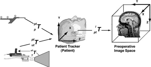
In the following discussion, we refer to various “spaces” as illustrated by . Each defines a Cartesian coordinate system attached to a system component, i.e., the pointer, the ultrasound probe tracker, the patient, or the patient's images. These coordinate systems may be related to each other using 4×4 transformation matrices. These can either be rigid-body transformations, including rotation and translation, or affine transformations, which are rigid body transformations with the addition of scaling and shearing. Referring to and assuming that the brain and skull form a rigid body, any point pi in pre-operative image space can be expressed as a point pu in intra-operative US image space with the following relation Citation[30]:where
is the affine transformation from US image to US probe tracker space,
is the rigid-body transformation from US probe tracker to the patient space, and
is the affine transformation from patient space to pre-operative patient image space.
is obtained from the tracking device itself,
is calculated via a calibration procedure described below, and
is derived using a patient-image registration procedure also described below.
Figure 1. The coordinate systems and the transformations relating them to each other.
Determining  through calibration
Prior to surgery, the components of the matrix describing the transformation (rotation, translation and image scaling) from ultrasound image to ultrasound probe tracker space (i.e., the coordinate system of the tracking sensor mounted on the US transducer) are determined using a calibration phantom designed for this purpose. Use of this phantom permits the calculation of the position of a fiducial marker on the ultrasound image in the phantom internal frame of reference, or phantom space (pps). The phantom itself has holes milled into it at known locations, so that the transformation of the phantom space to the position sensor space
can be determined by identifying these points using a tracked pointer. If a tracker is attached to the ultrasound probe during acquisition, then
(and thus
) is known for each acquired image. With this information, the location of fiducial markers in any image can be expressed in the common probe-tracker space by:
Thus we have the relation:
With pu and put,
is determined using a least squares minimization technique (similar calibration techniques can be found in reference Citation[41]). This procedure allows for multiple images of the phantom to be acquired, and thus many fiducial points to be accumulated and used in the calculation of
.
Patient-image registration
At the start of the surgical procedure, the transformation from the patient space to the MR image space, , is determined by identifying a series of anatomical landmarks on the MR images (with the computer mouse) and also on the patient (with the tracked pointer). A series of homologous point-pairs are thus obtained and used in a least-squares (SVD) minimization technique to determine the affine transformation (see reference Citation[30] for more details).
Thus, as US images (and corresponding US tracker orientations) are acquired during surgery, the transformation to a homologous oblique MRI slice is calculated by concatenating the set of transformations. The system can then store the coordinates of each acquired US image in patient space within the MINC format. This permits access to the corresponding MR slice of the patient, stored in the same coordinate space, and thus the simultaneous display and comparison of the pre-operative MRI and intra-operative US.
3D composite ultrasound volume
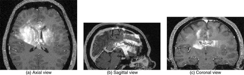
Once the sequence of acquired US images (a minimum of 20–30 images per sweep) are stored in the appropriate coordinate space, a composite 3D US is created by superimposing and averaging the slices into a filled 3D voxel volume (originally zero-valued) in the same coordinate frame as the MR volume acquired earlier. This is accomplished using a nearest-neighbor strategy that places each intensity pixel into the nearest voxel in the volume image. Because the images are stored in MINC format, tools are available to average the slices in the areas where they intersect. Should substantial overlap occur between slices, the averaging operator can improve image quality (i.e., SNR) by suppressing speckle noise, as it is decorrelated in slices acquired from different directions Citation[38], Citation[42]. Conversely, averaging acts to highlight anatomical features that appear in several intersecting slices. Speckle noise and small acoustic artifacts are further suppressed through a blurring operation on the resulting composite volume. Rohling et al. Citation[38] introduce additional strategies for reducing the effects of speckle noise and shadowing artifacts (see reference Citation[42]), as well as for correcting for linear registration errors through an image-based landmark registration algorithm. An example of an US volume superimposed onto a patient's MRI can be seen in .
Figure 2. 3D composite ultrasound volume: MRI in grey with US overlaid in a hot-metal color scale. (a) axial view; (b) sagittal view; (c) coronal view.
Pseudo US
In the absence of any brain shift, the intra-operative composite US volume is registered with the pre-operative MRI volume using the techniques described in the section on linear registration. However, the goal is to achieve voxel-to-voxel registration in the more realistic situation–in the presence of brain shift. To accomplish this, we seek a registration strategy that can compute the correspondences between the two data sets. Most available registration strategies often require similar features in the source and target volumes to perform the matching. Since US and MRI have very different characteristics and resolutions, we have developed a strategy to generate pseudo US images – images that predict the appearance of anatomical structures in the US images based on pre-operative MRI. In this manner, the deformation field based on optical flow between the pseudo US and the real, intra-operative US images acquired can be computed.
To generate the pseudo US images, the ANIMAL (Automatic Non-linear Image Matching and Anatomical Labeling) registration and segmentation package, developed in previous work Citation[43], is used to segment major brain structures from the MRI volume (See below for more details on the ANIMAL package.) The segmentation divides and labels the MR image into approximately 100 anatomical structures, including the larger structures such as the ventricles and white matter, as well as smaller structures such as the hypothalamus and the basal ganglia. However, many of these segmented tissues cannot be detected in US images. This leads to the careful selection of only those structures and liquid-filled volumes that generate sufficiently strong acoustic signals to be detectable in US images. Through examination of the clinical evidence, the pseudo US is generated based on the following anatomical structures: (i) white matter, (ii) cortical grey matter, (iii) structures containing cerebro-spinal fluid (CSF) such as the ventricles, some basal cisterns, sulci, and the longitudinal fissure, (iv) the caudate nucleus, and (v) the septum pellucidum. This includes structures that act as acoustic walls between anatomical structures (e.g., the septum), as well as volumes that filled with liquid (e.g., the sulci). Current research involves the extraction of a larger set of structures based on the examination of new clinical data sets (see Discussion section for details). It is important to emphasize that only a small subset of these structures will be visible in any given set of images, depending on the location of the craniotomy, the frequency range of the transducer, etc. The cysts, solid brain tumors and other pathologies (e.g., cavernomas) also generate strong acoustic signals, but these cases have to be handled on an individual basis. As the automatic segmentation of pathologies is an open research topic, the strategy currently involves manually segmenting them prior to surgery.
The resulting segmented volume of structures is then submitted to a radial gradient operator (originating at the tip of the ultrasound probe) to generate gradient magnitude data to simulate boundaries apparent in typical clinical US images. This gradient operator is radial about the origin of the US image (i.e., the location of the tip of the US probe).
An intensity remapping operation is then performed on the segmented structures and on the boundaries to attain a pseudo-acoustic density simulation that is comparable to the intensity profiles of intra-operative US brain images. Through examination of neurosurgical data, it was found that the acoustic signals in CSF-filled structures (e.g., between sulci), and in other liquid-filled structures (i.e., within cysts) must be mapped to high intensity values. Other structures generate weaker acoustic signals. For example, the caudate nucleus appears as a moderately bright, uniform structure. Borders between structures also have to be properly accounted for. For example, the CSF/white matter border appears as a bright signal, but the white/grey matter border is much weaker. The ventricles must be mapped to very low intensity values, but their borders with white matter and with each other (i.e., the septum) are mapped to very bright values.
The volumes of acoustic signals and boundaries are combined through an addition operator to create a pseudo US volume from the patient MRI. shows an example of each of the steps involved in creating a pseudo US image (pixel size 0.5 mm2). outlines a chart detailing the intensity mappings for the segmented structures depicted in . Note that these values were chosen empirically, based on samples of real patient US images.
Figure 3. Generating pseudo US. The original MRI is segmented using ANIMAL, a radial gradient is then applied, and these are merged to create a pseudo US image. a) original MRI; b) segmented MRI; c) gradient MRI; d) pseudo US.
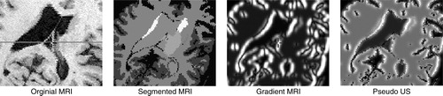
Table I. Intensity mappings for the pseudo US depicted in .
Non-linear registration – ANIMAL
The next goal is to perform the 3D non-linear registration from the intra-operative US acquired to the pseudo US volumes. To attain this goal, we once again adopt the versatile ANIMAL registration package developed in previous work Citation[43]. Using the linear transformation generated in the previous section as a starting point, the result is a non-linear spatial transformation mapping intra-operative US to the pseudo US volume. This transformation will later be used to map the US to pre-operative MRI (see below. In this section, an overview of the ANIMAL procedure will be described (for more details, see reference 43).
The ANIMAL Algorithm
The goal of ANIMAL is to estimate the non-linear transformation required to register two brain volumes. The transformation is a spatial mapping function from ℝ 3↠ℝ 3. To estimate the transformations, the ANIMAL procedure computes a dense field of 3D deformation vectors, mapping each voxel of one image volume to those in a target image volume. The algorithm assumes that the mapping function (i) varies smoothly over the entire field and (ii) is piecewise linear in the sense that, within a small neighborhood, the deformation field can be approximated locally by a translational flow field. During the implementation of the algorithm, the transformation is represented by a deformation field that is defined on a dense 3D cubic lattice with a 3D displacement vector stored for each node position in the lattice. Three scalar volumes are stored: dx, dy and dz, representing the x-, y- and z-components of the 3D displacement vectors. For all points (x, y, z) in the domain of the deformation function, the value of the corresponding 3D displacement is given by interpolation in each component volume.
To evaluate the match between source and target volumes, an optimization procedure is invoked to maximize similarity over some objective function. Ideally, the function would have a single maximum when the two volumes are fully registered. In practice, the objective function almost always has a complex shape with multiple local maxima. A global multi-resolution strategy (described later) is developed to minimize the probability of getting stuck at a local maximum, as would be the case if the procedure were applied only once at the finest scale.
The objective function chosen is formulated in terms of a summation of similarity and cost terms:𝒮 and 𝒯 are the source and target volumes, respectively, N is the non-linear transformation represented by the deformation field that maps points from 𝒮 to 𝒯, R() is the local similarity measure and C() is the cost function that penalizes large transformations. The summation is evaluated over all nodes,
, in the 3D lattice, L, of the deformation field, and is normalized by n, the number of nodes.
While a number of functions for evaluating the local similarity between the two data sets are made available within the ANIMAL registration package (e.g., cross-correlation, optical flow, etc.), for the purposes of this paper, we have decided to use a standard normalized correlation to measure and compute the required deformation vector:where
is the local neighborhood of
with diameter=1.5 FWHM (FWHM is the full-width-half-maximum of the Gaussian kernel that describes the resolution or scale of the deformation field), and f() is the volumetric interpolation function. The summation is performed over all voxel elements
When the two volumes are in perfect registration, R() and S() take on a maximum value of 1.0. ANIMAL can use nearest-neighbor, tri-linear or tri-cubic interpolation for f(). Experience has shown that tri-linear interpolation is sufficient when applied to super-sampled data and results in a significant speed improvement over tri-cubic interpolation. Unlike a global normalized correlation metric, the local correlation function has the advantage that it is robust against image intensity non-uniformity. As such, it accounts for attenuation effects in the US image, thereby removing the need to account for these effects explicitly in the registration.
A cost function is used to penalize large estimated deformation vectors. Although it can take on many forms, the following function has been selected:where d is the length of the additional deformation vector estimated at node
at the current iteration. The constant dmax is set to the magnitude of the current FWHM. To ensure that small deformations are not overly penalized, c is set to 0.2. The shape of the function is relatively flat until d approaches dmax.
Constraints are applied to the estimation procedure to ensure that the resulting deformation field is continuous. The constraints prohibit (i) two distinct points being compressed together, (ii) an overlap in fields, or (iii) a tearing of the field. To meet these constraints, the deformation field is smoothed such that the vector at each node is averaged with the deformation vectors of the neighboring nodes. Suppose is the mean deformation vector averaged over its immediate neighbourhood
. The resulting deformation is then given by a linear combination of the computed deformation and the average such that:
where the weight α varies from 0 to 1. A small α value leads to a very smooth deformation field, possibly at the expense of missing some small local variations, and requires many iterations to arrive at the solution. A large α value gives more weight to the estimated deformation vector and converges faster, while risking the possibility of local discontinuities in the global deformation field. Empirically, we have found that α=0.5–0.8 provides an acceptable compromise between local matching and global smoothness.
At each scale, the estimation/smoothing process is repeated iteratively on the partially deformed fields. To reduce the possibility of large local shifts causing large distortions on the deformation field, only a fraction of the estimated deformation vector for each node is applied at each iteration. It was determined that a fractional value of 0.6 for the deformation weight and 30 iterations is a reasonable compromise between speed and noise stability.
A multi-resolution strategy is used to speed up the estimation process and to avoid local minima in the objective function hyper-surface. The iterative optimization procedure described above is repeated in a hierarchical multi-scale fashion where the registration is performed at different spatial scales. First, blurred data of the source and target volumes are used to estimate the largest and most global deformations, and then the transformation is refined by using less blurred data and finer grid sampling to account for more local deformations. The output of one stage is fed as input to the next level, thus refining the registration. In practice, we use two hierarchical steps. In the first, the data volumes are blurred with an 8 mm FHWM Gaussian kernel and a deformation grid with 4 mm separation between nodes. In the second, data are blurred with a 4 mm kernel and the grid step size is 2 mm.
Updating patient MRI
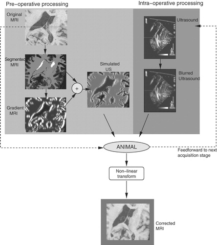
Ideally, an update of the patient's MRI would be provided at various stages of the surgical procedure. Depending on the case, the stages of interest might include those prior to the opening of the dura, after the dura is opened, prior to a tumor resection, during the resection, after the resection and at the end of the procedure. To meet these goals, the ANIMAL package is used at each stage to estimate the non-linear spatial transformation mapping the pseudo US image volume to the 3D composite US volume acquired. This same transformation can be used to update the patient's MRI during surgery, thus permitting the neurosurgeon to make use of the pre-operative images during the intervention, even in the presence of a brain deformation (and errors in the linear registration from the patient to the pre-operative images). Subsequent image acquisition stages use the transformation acquired from a previous stage as a starting point for ANIMAL's optimization procedure. A flowchart of the entire system can be seen in .
Figure 4. Flowchart of the non-linear registration system.
Results: clinical applications
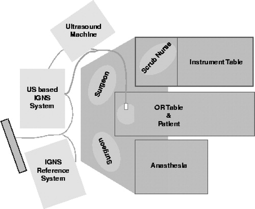
The method was applied to 12 surgical cases, including those with brain tumors (n=8) and selective amygdalo-hippocampectomies (n=4). Pre-operative MRIs were acquired using a Philips 1.5T Gyroscan (Philips, The Netherlands). Intra-operative US image acquisition was performed using an Ultramark 9 (Advanced Technologies Laboratories, Inc., Bothwell, WA) machine with an ATL P7-4 multi-frequency probe and a Capsure™ frame grabber (Power Macintosh G3/AV) on a Macintosh computer (Apple, Cupertino, CA). Tracking was achieved with the use of a Polaris tracking system with an active probe. shows the schematic diagram describing the relative positions of the IGNS systems in the operating room. Through examination of the surgical set-up, it becomes apparent that the system is not cumbersome and does not hinder, in any way, the activities of the surgical staff.
Figure 5. Operating room floor plan. The experimental US-MRI IGNS system is used in conjunction with a standard commercial IGNS reference system (SNN, Cedera, Toronto, Canada).
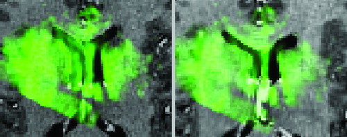
The feasibility of the approach was demonstrated through examination of the qualitative results from three clinical cases. shows the case of an amygdalo-hippocampectomy for intractable epilepsy. US images were acquired at two different stages of the operation: before and after the opening of the dura. A deformation of the left lateral ventricle was observed at each stage of image acquisition – a slight deformation prior to opening the dura, and then a larger displacement once the dura was opened. The figure illustrates how the system was able to correct for brain deformations at each of these two stages of surgery. This can be seen as the corrected MRIs appropriately reflect the new positions of the deformed left lateral ventricles. The extent of the correction can be seen in , where the US after the opening of the dura is seen overlayed in green over the original and corrected MRIs. Notice that the corrected MRI matches the US image more accurately, particularly around the ventricles.
Figure 6. Left selective amygdalo-hippocampectomy for intractable epilepsy: zoom of transverse images through the lateral ventricles. Patient was in the supine position with the head turned on the right side. A slight brain deformation is visible before the dura opening (column 2). A larger gravitational displacement (towards the right of the image) of the median structures is observed after dura opening (column 3). The deformation mainly involves the anterior horn of the left lateral ventricle (white arrow), whereas the falx (arrowhead) and septum pellucidum (double arrowhead) do not move. Correction of the deformation is demonstrated during these two surgical steps.
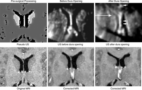
Figure 7. Case from illustrating US (in green) after dura opening over original MRI (left) and over corrected MRI (right). Notice the distinct collapse of the left lateral ventricle.
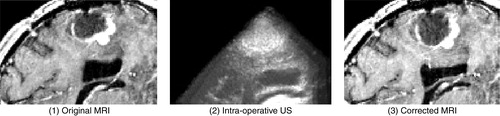
illustrates the case of a resection of a right, frontal malignant tumor. Here, US images were acquired after the dura opening, when significant brain deformation (on the order of 8 mm) had occurred in the form of the sinking of the tumor as well as other deep-seated structures. The strategy was able to correct for the deformations of both pathological and anatomical structures.
Figure 8. Case with right frontal recurrent malignant tumor. Left: intra-operative MRI; center: intra-operative US; right: corrected MRI. These near-transverse images show the tumor (top) and ventricles (bottom), with the front of the head towards the right. After dura opening, the sinking of the entire tumor, as well as the deeply-seated median structures, are clearly visible as a displacement towards the bottom of the image. The MRI is corrected for deformations of both pathological and anatomical structures (e.g., the ventricle is displaced and slightly compressed; the tumor is also displaced). The posterior part of the septum drops, but the anterior part does not as the registration system confuses it with the choroid plexus. This will be fixed with proper representation of the septum and choroid plexus in the simulations. Note that the falx does not move.
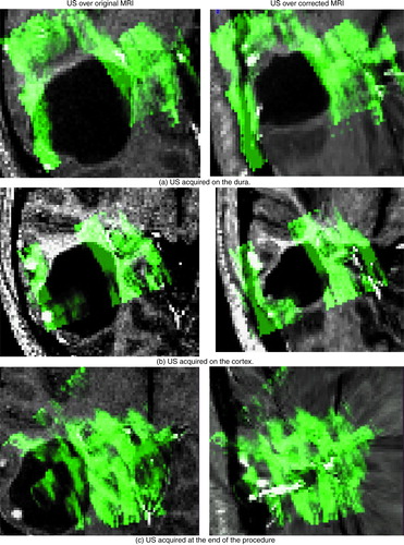
indicates similar success for a different tumor resection case. Here, US images were acquired on the dura, on the cortex after the opening of the dura, and at the end of the procedure. The figure depicts the US images in green overlaid onto both the original MRI (left column) and the updated MRI (right column) based on the acquired US. The system was able to successfully correct for deformations (i.e., shrinking) in the tumor boundary. This is particularly evident at the end of the procedure, when the tumor was completely resected. Here, no tumor was visible in the US image – only a cavity filled with liquid was left (as indicated by the uniform green mass). The success of the strategy is indicated by the fact that the updated MRI accurately reflects the missing tumor. This is noteworthy as, in general, the disappearance of a structure in one set of images presents a significant challenge to most image matching procedures. In all surgical cases, it took approximately 30 sec of processing time to provide a corrected MRI volume on average.
Figure 9. Tumor case. The ultrasound images acquired at various stages in the procedure are displayed in green overlaid onto the original MRI (left column) and onto the corrected MRI (right column). The images were acquired as follows: (a) on the dura surface; (b) on the cortex after the opening of the dura; and (c) at the end of the procedure. These transverse images depict the tumor in black. Notice that the corrected MRIs (on the right) depict more closely the surgical reality as reflected by the US images than do the original MRIs. This is particularly evident at the end of the procedure when the tumor has been resected, and was no longer visible in the US image. The final corrected MRI accurately reflects the absence of the tumor.
quantifies the extent to which the correction for non-linear deformations improves the correspondences between various anatomical structures or pathologies visible in the US and MR images. Here, we examine the cases depicted in , and . The basis on which we choose to track a particular structure is the degree to which it deformed and its relative importance to the procedure from a clinical perspective. The table depicts the average distance in mm between the structures in the US and MR images before and after the correction for brain deformations. This quantification is based on rough computations of the movement of the borders of the structures of interest. As such borders are not always clear on the US, the calculations are approximate. The table examines the results for the states before and after the opening of the dura (when such data are present). The results indicate that our strategy significantly improves the registration by successfully correcting for the non-linear deformations.
Table II. Quantification of registration error before and after correction for non-linear brain deformations. The table depicts the average distance in mm between key anatomical structures or pathologies visible in the US and MR images for the cases described. The results before and after correction for brain deformations are shown for the states prior to and after the dura was opened. Note that in the case of , no data was acquired on the dura.
Discussion and conclusion
In the context of image-guided craniotomies for brain lesions, there are three important issues to address: (i) finding the lesions; (ii) avoiding the eloquent, functional brain tissue; and (iii) determining the borders between pathological and normal brain tissues. Over the past decade, advances in IGNS systems have permitted neurosurgeons to reach these objectives in a large number of situations Citation[1]. However, because of the frequent occurrence of brain deformations during craniotomies, the accuracy of the neuronavigation system is often compromised. In this paper, we have presented a method for the automatic correction for brain deformations during craniotomies by using a non-linear registration strategy that automatically matches pre-operative MRI to intra-operative US. The strategy is based on cross-correlation measurements generated from the ANIMAL registration package that map pseudo US images, derived from pre-operative MRI, to intra-operative US images. Others have also attempted to remap MRI intensities in such a way as to resemble US images, through gradient computations and intensity remappings Citation[32], Citation[34]. We expand on this idea by extracting from the MRI those anatomical structures that are visible in the US, and building the first MRI-generated US pseudo-simulations.
Current work involves building more realistic and sophisticated US simulations, based on the identification of a larger number of neuro-anatomical structures in clinical US data. A more comprehensive list of appropriate structures is being compiled as more clinical data is gathered. In recent cases, for example, evidence was found in the US images for the following additional structures: the lenticular nucleus, the choroid plexus, the corpus callosum, the cerebral falx, some basal cisterns, blood vessels, and some gyri (especially if separated by two main sulci).
As further clinical evidence for these and other additional structures is accumulated, they will be added to the pseudo US. Furthermore, although reasonable results were attained with the current approach, future work will embed more realistic, physical modeling of the acoustic phenomenon into the simulations. For example, real US images suffer from spatially variant resolution and attenuation effect which must be accounted for in the simulations.
One important advantage of the IGNS system presented in this paper, encouraging its adoption in the operation room, is its ease of use. In contrast to most of the interventional MRI systems that are currently available, the surgeon and staff are not restricted in their access to the patient. In addition, there are no constraints placed on the types of surgical tools permissible during the procedure: standard tools can be used. The US image quality is also not affected by the presence of nearby equipment. Furthermore, the cost of the entire system is one tenth that of an interventional MRI system.
Another important advantage of the system is its relative speed. Pre-operative processing time for the creation of the pseudo US image, including the segmentation and gradient computations, is less than 10 min. Intra-operative computations include: performing the US acquisition (2–3 min), computing the composite US volume (2 min) and finally, computing the deformations and updating the MRI (30 sec). Optimization of the US composition should reduce the latter step to several seconds, and we are currently working on a real-time version of the system.
One disadvantage of a US-based IGNS strategy is that the visibility of structures close to the surface of the brain is limited as image acquisition depends on direct contact of the imaging tool with the cortex of the patient. Should the surgeon require accurate tracking of these structures over the course of the operation (e.g. tracking tumors near the surface), specific care must be taken in the positioning of the transducer to ensure that these appear in the US images. Limitations of the particular system described in this paper include the fact that it is not currently integrated with the existing surgical tools, such as the microscope and the commercial IGNS system. In addition, there is no technique to automatically account for pathologies.
The standard criticism associated with the use of US during neurosurgical procedures is related to its poor spatial and contrast resolutions, making it difficult for humans to easily discern many structures of interest using this modality in isolation. Furthermore, only a relatively small number of visible anatomical structures can be reliably extracted from US images in the first place and, during a given procedure, only a subset of these can be relied upon to be present in the images (depending on the location of the craniotomy, the frequency range of the probe, etc.). Our approach minimizes these concerns by providing the neurosurgeon with high resolution MR, warped to reflect the surgical reality, based on US images acquired intra-operatively. Clinical applications performed on 12 patients have demonstrated the feasibility and the reliability of the method. We are currently in the process of extending the database to include more patient cases. In addition, a more rigorous validation of the methodology is being devised in order to better quantify the registration error through experimentation with both brain and phantom images.
From a clinical perspective, quantitative analysis is required to assess the added clinical value of the approach to the real patient outcomes. Future work will also entail building an interface to provide the neurosurgeon with the means to participate in the registration error control process.
References
- Dorward N. Neuronavigation – the surgeon's sextant. Br J Neurosurg 1997; 11: 101–3
- Golfinos J, Fitzpatrick B, Smith L, Spetzler R. Clinical use of a frameless stereotactic arm: result of 325 cases. Neurosurgery 1995; 83: 197–205
- Hill D, Maurer C, Maciunas R, Barwise J, Fitzpatrick J, Wang M. Measurement of intraoperative brain surface deformation under a craniotomy. Neurosurgery 1998; 43: 514–28
- Paleologos T, Wadley J, Kitchen N, Thomas D. Clinical utility and cost-effectiveness of interactive image-guided craniotomy: clinical comparison between conventional and image-guided meningioma surgery. Neurosurgery 2000; 47: 40–8
- Maurer C, Aboutanos G, Dawant B, Gadamsetty S, Margolin R, Maciunas R, Fitzpatrick J. Effect of geometrical distortion correction in MR on image registration accuracy. J Comp Assist Tomogr 1996; 20: 666–79
- Roberts D, Hartov A, Kennedy F, Miga M, Paulsen K. Intraoperative brain shift and deformation: a quantitative analysis of cortical displacement in 28 cases. Neurosurgery 1998; 43: 749–60
- Nabavi A, Black P, Gering D, Westin C, Mehta V, Pergolizzi R, Ferrant M, Warfield S, Hata N, Schwartz R, Wells W, Kikinis R, Jolesz F. Serial intraoperative magnetic resonance imaging of brain shift. Neurosurgery 2001; 48: 787–98
- Black P, Alexander E, Martin C, Moriarty T, Nabavi A, Wong T, Schwartz R, Jolesz F. Craniotomy for tumor treatment in an intraoperative magnetic resonance unit. Neurosurgery 1999; 45: 423–33
- Bernstein M, Al-Anazi A, Kurcharczyk W, Manninen P, Bronskill M, Henkelman M. Brain tumor surgery with the Toronto open magnetic resonance imaging system: preliminary results for 36 patients and analysis of advantages, disadvantages, and future prospects. Neurosurgery 2000; 46(4)900–7
- Wirtz C, Bonsanto M, Knauth M, Tronnier V, Albert F, Staubert A, Kunze S. Intraoperative magnetic resonance imaging to update interactive navigation in neurosurgery: Method and preliminary experience. Comput Aided Surg 1997; 2: 172–9
- Roberts D, Miga M, Hartov A, Eisner S, Lemery J, Kennedy F, Paulsen K. Intraoperatively updated neuroimaging using brain modeling and sparse data. Neurosurgery 1999; 45: 1199–1207
- Miga M, Paulsen K, Lemery J, Eisner S, Hartov A, Kennedy F, Roberts D. Model-updated image guidance: Initial clinical experiences with gravity-induced brain deformation. IEEE Trans Med Imag 1999; 18: 866–74
- Miga M I, Paulsen K D, Kennedy F E, Hartov A, Roberts D W (1999) Model-updated image-guided neurosurgery using the finite element method: Incorporation of the falx cerebri. Proceedings of Second International Conference on Medical Image Computing and Computer-Assisted Intervention (MICCAI '99), CambridgeEngland, September, 1999, C Taylor, A Colchester. Springer, Berlin, 900–9, Lecture Notes in Computer Science 1679
- Castellano-Smith A, Hartkens T, Schnabel J, Hose D, Liu H, Hall W, Truwit C, Hawkes D, Hill D (2001) Constructing patient specific models for correcting intraoperative brain deformations. Proceedings of Fourth International Conference on Medical Image Computing and Computer-Assisted Intervention (MICCAI 2001), UtrechtThe Netherlands, October, 2001, W Niessen, M A Viergever. Springer, Berlin, 1091–99, Lecture Notes in Computer Science 2208
- Audette M, Siddiqi K, Peters T (1999) Level-set surface segmentation and fast cortical range image tracking for computing intrasurgical deformations. Proceedings of Second International Conference on Medical Image Computing and Computer-Assisted Intervention (MICCAI '99), CambridgeEngland, September, 1999, C Taylor, A Colchester. Springer, Berlin, 788–97, Lecture Notes in Computer Science 1679
- Audette M, Ferrie F, Peters T. An algorithmic overview of surface registration techniques for medical imaging. Med Image Anal 2000; 4: 201–17
- Gronningsaeter A, Unsgard G, Ommedal S, Angelsen B. Ultrasound-guided neurosurgery: a feasibility study in the 3–30 MHz frequency range. Br J Neurosurg 1996; 10: 161–68
- Hammoud M, Ligon B L, ElSouki R, Shi W, Schomer D, Sawaya R. Use of intraoperative ultrasound for localizing tumors and determining the extent of resection: a comparative study with magnetic resonance imaging. Neurosurgery 1996; 84: 737–41
- Koivukangas J, Louhisalmi Y, Alakuijala J, Oikarinen J. Ultrasound controlled neuronavigator-guided brain surgery. Neurosurgery 1993; 79: 36–42
- Sutcliffe J. The value of intraoperative ultrasound in neurosurgery. Br J Neurosurg 1991; 5: 169–78
- Comeau R, Sadikot A, Fenster A, Peters T. Intraoperative ultrasound for guidance and tissue shift correction in image-guided neurosurgery. Med Phys 2000; 27: 787–800
- Gronningsaeter A, Kleven A, Ommedal S, Aarseth T, Lie T, Lindseth F, Lango T, Unsgard G. Sonowand an ultrasound-based neuronavigation system. Neurosurgery 2000; 47: 1373–80
- Trobaugh J, Richard W, Smith K, Bucholz R. Frameless stereotactic ultrasonography: Methods and applications. Computerized Medical Imaging and Graphics 1994; 18(4)235–46
- Hata N, Dohi T, Iseki H, Takakura K. Development of a frameless and armless stereotactic neuronavigation system with ultrasonographic registration. Neurosurgery 1997; 41: 608–13
- Hirschberg H, Unsgaard G. Incorporation of ultrasonic imaging in an optically coupled frameless stereotactic system. Acta Neurochir 1997; 68(Suppl)75–80
- Bucholz R, Sturm C, Henderson J. Detection of brain shift with an image guided ultrasound device. Acta Neurochirurgica 1996; 138: 627
- Bucholz R D, Yeh D D, Trobaugh J, McDurmont L L, Sturm C D, Baumann C, Henderson J M, Levy A, Kessman P (1997) The correction of stereotactic inaccuracy caused by brain shift using an intraoperative ultrasound device. Proceedings of First Joint Conference on Computer Vision, Virtual Reality and Robotics in Medicine and Medical Robotics and Computer-Assisted Surgery (CVRMed-MRCAS '97), GrenobleFrance, March, 1997, J Troccaz, E Grimson, R Mösges. Springer, Berlin, 459–66, Lecture Notes in Computer Science 1205
- Erbe H, Kriete A, Jödicke A, Deinsberger W, Böker D K (1996) 3D-ultrasonography and image matching for detection of brain shift during intracranial surgery. Computer Assisted Radiology. Proceedings of the International Symposium on Computer and Communication Systems for Image Guided Diagnosis and Therapy (CAR '96), Paris, June, 1996, H U Lemke, M W Vannier, K Inamura, A G Farman. Elsevier, Amsterdam, 225–30
- Jödicke A, Deinsberger W, Erbe H. Intraoperative three-dimensional ultrasonography: an approach to register brain shift using multidimensional image processing. Minimally Invasive Neurosurgery 1998; 41: 13–9
- Comeau R M, Fenster A, Peters T. Intraoperative US in interactive image-guided neurosurgery. Radiographics 1998; 19(4)1019–27
- Gobbi D G, Comeau R M, Peters T M (2000) Ultrasound/MRI overlay with image warping for neurosurgery. Proceedings of third International Conference on Medical Image Computing and Computer-Assisted Intervention (MICCAI 2000), PitsburghPA, October, 2000, S L Delp, A M DiGioia, B Jaramaz. Springer, Berlin, 106–14, Lecture Notes in Computer Science 1935
- Roche A, Pennec X, Rudolph M, Auer D P, Malandain G, Ourselin S, Auer L M, Ayache N (2000) Generalized correlation ratio for registration of 3D ultrasound with MR images. Proceedings of Third International Conference on Medical Image Computing and Computer-Assisted Intervention (MICCAI 2000), Pittsburgh, PA, October, 2000, S L Delp, A M DiGioia, B Jaramaz. Springer, Berlin, 567–77, Lecture Notes in Computer Science 1935
- Lunn K, Hartov A, Hansen E, Sun H, Roberts D, Paulsen K (2001) A quantitative comparison of edges in 3D intraoperative ultrasound and preoperative MR images of the brain. Proceedings of Fourth International Conference on Medical Image Computing and Computer-Assisted Intervention (MICCAI 2001), UtrechtThe Netherlands, October, 2001, W Niessen, M A Viergever. Springer, Berlin, 1081–90, Lecture Notes in Computer Science 2208
- Guimond A, Roche A, Ayache N, Meunier J. Three-dimensional multimodal brain warping using the demons algorithm and adaptive intensity corrections. IEEE Trans Med Imag 2001; 20: 58–69
- King A P, Blackall J M, Penney G P, Edwards P J, Hill D LG, Hawkes D J (2000) An estimation of intra-operative deformation for image-guided surgery using 3-D ultrasound. Proceedings of Fourth International Conference on Medical Image Computing and Computer-Assisted Intervention (MICCAI 2001), Pitsburgh, PA, October, 2000, S L Delp, A M DiGioia, B Jaramaz. Springer, Berlin, 588–97, Lecture Notes in Computer Science 1935
- Fenster A, Downey D. 3-D ultrasound imaging: A review. IEEE Engineering in Medicine and Biology 1996; 15(6)41–51
- Prager R, Rohling R, Gee A, Berman L. Rapid calibration for 3-D freehand ultrasound. 1998; 24(6)855–69, Ultrasound in Medicine and Biology
- Rohling R N, Gee A H, Berman L. Three-dimensional spatial compounding of ultrasound images. Med Image Anal 1997; 1: 177–93
- Rohling R, Gee A, Berman L. A comparison of freehand three-dimensional ultrasound reconstruction techniques. Med Image Anal 1999; 3: 339–59
- Neelin P, MacDonald D, Collins D, Evans A. The {MINC} file format: from bytes to brains. NeuroImage 1998; 7(4)786
- Blackall J M, Rueckert D, Maurer C R, Jr, Penney G P, Hill D LG, Hawkes D J (2000) An image registration approach to automated calibration from freehand 3D ultrasound. Pitsburgh, PA, October, 2000, S L Delp, A M DiGioia, B Jaramaz. Springer, Berlin, 463–70, Lecture Notes in Computer Science 1935
- Burkhardt C B. Speckle in ultrasonic B-mode scans. IEEE Trans Sonics Ultrason 1998; SU-25: 1–25
- Collins D L, Evans A C. ANIMAL: validation and applications of non-linear registration-based segmentation. Int J Pattern Recog Artificial Intell 1997; 11: 1271–94