Abstract
Objective: The restoration of a normal mechanical axis of the lower limb following total knee prosthesis (TKP) depends on the accuracy of the intra-operative measurement of the femoro-tibial angle. We have studied the reproducibility of intra-operative measurement of the coronal mechanical femoro-tibial axis with the OrthoPilot® (Aesculap, Tuttlingen, Germany) non-image-based navigation system.
Material and Methods: A consecutive series of 20 TKP (Aesculap SEARCH Evolution® prosthesis) implanted by the same surgical team of two senior orthopedic surgeons was analyzed. They used a non-image-based navigation system that allows the mechanical axes of the femur and tibia to be defined with a kinematic analysis. The operating surgeon and assistant surgeon performed the kinematic analysis twice and once, respectively, and measured coronal mechanical femoro-tibial angles in maximal extension and at 90° flexion without varus or valgus stress.
Results: The mean intra-observer variation in the measurement of the coronal mechanical femoro-tibial angle in maximal extension was 0.1° (SD=0.7°). The mean intra-observer variation in the measurement of the coronal mechanical femoro-tibial angle at 90° of knee flexion was 0.2° (SD=0.6°). The mean inter-observer variation in the measurement of the coronal mechanical femoro-tibial angle in maximal extension was 0.1° (SD=0.7°). The mean inter-observer variation in the measurement of the coronal mechanical femoro-tibial angle in maximal extension was 0.0° (SD=0.6°). There were no significant differences and a high correlation between all paired intra- and inter-observer measurements.
Conclusion: This system allows high reproducibility of the intra-operative measurement of the mechanical axes of the lower limb by a non-image-based kinematic registration of the hip, knee and ankle centers.
Introduction
The restoration of a normal mechanical axis of the lower limb is an accepted prognostic factor for long-term survival of a total knee prosthesis (TKP) Citation[1–3]. Such restoration depends on the accuracy of the intra-operative measurement of the femoro-tibial angle. Conventional surgeon-controlled instrumentations with intra- or extramedullary guides can lead to sub-optimal implantations, with rates of unsatisfactory radiological implantations exceeding 10% Citation[3], Citation[4]. A computer-assisted navigation system might improve the quality of implantation in comparison to that obtained with conventional instrumentations Citation[5] by allowing higher accuracy in the intra-operative definition of the relevant axes. Few systems are currently being used clinically; only two have been clinically validated by a prospective, randomized, controlled study Citation[6], Citation[7] or case-control studies Citation[8], Citation[9]. These studies showed that the rate of optimal correction of the mechanical femoro-tibial axis on long-leg post-operative X-rays was higher following navigated implantation than after conventional implantation. However, the reproducibility of these systems has never been evaluated. The authors have studied the reproducibility of intra-operative measurement of the mechanical axes of the lower limb by a kinematic analysis with the OrthoPilot ® (Aesculap, Tuttlingen, FRG) non-image-based navigation system.
Materials and methods
Material
A consecutive series of 20 TKPs (SEARCH Evolution® prosthesis, Aesculap, Tuttlingen, FRG) Citation[10] implanted by the same surgical team of two senior orthopedic surgeons was analyzed. We used a non-image-based navigation system that allows the mechanical axes of the femur and tibia to be defined with a kinematic analysis, and relevant anatomical points to be palpated with a stylus.
Operative technique
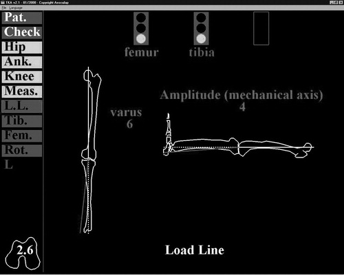
The complete operative technique has been described in detail elsewhere Citation[6], Citation[8], Citation[9]. Briefly, three infrared localizers were implanted on screws in the anterior iliac crest, distal femur, and proximal tibia, with a fourth strapped on the dorsal part of the foot (). The relative motion of two adjacent localizers was observed by an infrared camera (Polaris®, Northern Digital, Inc., Waterloo, Ontario, Canada). The dedicated software calculated the center of rotation of this movement, which was the respective center of rotation of the hip, knee and ankle joints. The three-dimensional location of these centers allowed the mechanical axes of the femur and tibia to be determined on both coronal and sagittal planes. Direct palpation with a stylus of the most posterior point of both femoral condyles, along with the center of the hip joint, allowed the reference coronal plane to be defined. Three-dimensional positioning of both the femur and tibia was tracked, and the angle between the femoral and tibial axes was directly calculated and displayed online by the dedicated software in both coronal and sagittal planes ().
Figure 1. Intra-operative view of the femoral, tibial and ankle localizers.
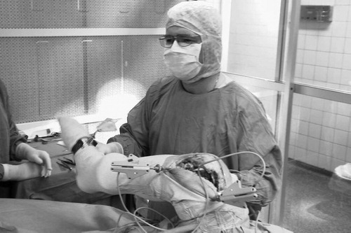
Figure 2. Display of axes on the monitor.
Mathematical algorithms
Hip center determination
The hip joint can be modeled with a classical ball-and-socket joint, which is characterized by a point invariant in any attitude of the joint. By collecting n positions of a femur point (xi, yi, zi) in the pelvis frame of reference, it is possible to search for a point (xc, yc, zc) which minimizes the following classical quantity:where R is the radius of the sphere described by the femur point in the pelvis frame of reference. Many mathematical methods, in particular the Levenberg-Marquardt method Citation[11], enable this minimization problem to be solved.
Ankle center determination
The ankle joint can be modeled with a hinge joint, which is characterized by one axis remaining invariant during joint flexion. However, the talus is rotating in various planes due to the conical shape of the trochlea, and an axial rotation exists in extension. It is thus possible to model the ankle joint as a ball and socket, where the minimization of the above quantity will determine a point on the main rotation axis, centered in the joint.
Due to the possibility of perturbations in ankle flexion/extension (small range of motion, external fixation of trackers), some local minima may exist during the minimization process. This is solved by using as an initial condition of the minimization an anatomical determination of the ankle center (external palpations of malleoli and the anterior point of the distal tibia), and by restricting the minimization domain to the neighborhood of this anatomical ankle center.
Knee center determination
The knee center can also be modeled with a hinge joint in extension situation, but an obvious tibial rotation exists in flexion. The same approach used for the ankle can be applied to assimilate the knee joint to a ball-and-socket model. This model provides a single point; the opposite of the well-known instantaneous centers of rotation of the knee joint. The main characteristic of this single point is to globally minimize the joint kinematics to find a unique mechanical axis for both the tibia and femur Citation[5]. As for the ankle center determination, some local minima may exist during the minimization process, mainly due to the various discrepancies of the joint surface. This is solved in the same way as before by using an anatomical knee center defined with external palpations (the most posterior points of the medial and distal condyles, and the anterior point on the distal femur).
Angle computation
Values of lower limb characteristic angles (i.e., varus/valgus and flexion/extension) are given by the angular position of the tibial mechanical axis within the femoral frame of reference. We chose to follow the Euler angle definition Citation[12], which is close to the technique of Ramadier et al. Citation[13] that is commonly accepted for radiological measurement of knee deformations.
The mechanical axis of the femur is defined by the line containing both hip and knee centers. The posterior condylar axis is defined by joining the most posterior points of the medial and lateral condyles. The femoral frontal plane is defined by the plane containing the femoral axis and lying parallel to the posterior condylar axis. The femoral sagittal plane can then be defined by its mechanical axis and a cross product of the posterior condylar axis with this mechanical axis. The tibial mechanical axis is defined by the line containing both ankle and knee centers. The varus/valgus value is defined by the angle measurement between the tibial mechanical axis and the femoral sagittal plane. The flexion/extension angle value is defined by the angle measurement between the projection of the tibial mechanical axis on the femoral sagittal plane and the femoral mechanical axis.
Methods
Three kinematic registrations of the hip, knee and ankle joints were performed during the same procedure – two by the operating surgeon (surgeon 1) and one by the assistant surgeon (surgeon 2) – without changing the anatomic palpation. Coronal mechanical femoro-tibial angles in maximal extension and at 90° flexion without varus or valgus stress were measured after each kinematic registration. Intra-observer variations were examined using an ANOVA test for repeated measurements and a Spearman correlation test. Inter-observer variation was studied by comparing the mean value of each case for surgeon 1 to the value for surgeon 2 with a paired Wilcoxon t-test and a Spearman correlation test. All statistical tests were performed with a 0.05 level of significance.
Results
Results for all cases are presented in . The mean intra-observer variation in the measurement of the coronal mechanical femoro-tibial angle in maximal extension was 0.1° (SD=0.7°); all paired differences were ≤1°, except for one case with a 2° difference. The mean intra-observer variation of the measurement of the coronal mechanical femoro-tibial angle at 90° of knee flexion was 0.2° (SD=0.6°); all paired differences were ≤1°.
Table I. Results.
The mean inter-observer variation in the measurement of the coronal mechanical femoro-tibial angle in maximal extension was 0.1° (SD=0.7°); all paired differences were ≤1°, except for one case with a 1.5° difference and one with a 2° difference. The mean inter-observer variation of the measurement of the coronal mechanical femoro-tibial angle in maximal extension was 0.0° (SD=0.6°); all paired differences were ≤1°, except for two cases with a 1.5° difference. There were no significant differences (paired Student t-test) and a high correlation (Spearman correlation test, p<0.000.1) between all paired intra- and inter-observer measurements.
Discussion
Restoration of a normal limb axis is a major goal of the implantation of a TKP. Computer-assisted techniques have been shown to increase the rate of optimally implanted prostheses on post-operative X-rays. While the accuracy of such systems has already been studied both experimentally Citation[5] and clinically Citation[6–9], the reproducibility of the intra-operative measurements remained to be defined. The system used in the present study enabled high intra- and inter-observer reproducibility for intra-operative registration of the centers of rotation of the hip, knee and ankle joints. Intra-operative measurements of the mechanical femoro-tibial angles using this system can thus be expected to be reliable. However, the current version of the software includes a modified algorithm for hip center registration without the use of a pelvic localizer, and the reproducibility of this new technique has yet to be assessed.
References
- Feng E L, Stulberg S D, Wixson R L. Progressive subluxation and polyethylene wear in total knee replacements with flat articular surfaces. Clin Orthop 1994; 299: 60–71
- Jeffery R S, Morris R W, Denham R A. Coronal alignment after total knee replacement. J Bone Joint Surg (Br) 1991; 73: 709–14
- Ritter M A, Faris P M, Keating E M, Meding J B. Postoperative alignment of total knee replacements: its effect on survival. Clin Orthop 1994; 299: 153–6
- Teter K E, Bergman D, Colwell C W. Accuracy of intramedullary versus extramedullary tibial alignment cutting systems in total knee arthroplasty. Clin Orthop 1995; 321: 106–10
- Delp S L, Stulberg S D, Davies B, Picard F, Leitner F. Computer assisted knee replacement. Clin Orthop 1998; 354: 49–56
- Saragaglia D, Picard F, Chaussard C, Montbarbon E, Leitner F, Cinquin P. Mise en place des prothèses totales du genou assistée par ordinateur: comparaison avec la technique conventionnelle. Rev Chir Orthop 2001; 87: 18–28
- Sparmann M, Wolke B, Czupalla H, Banzer D, Zink A. Positioning of total knee arthroplasty with and without navigation support. A prospective, randomized study. J Bone Joint Surg (Br) 2003; 85: 830–5
- Jenny J Y, Boeri C. Computer-assisted implantation of total knee prostheses: a case control comparative study with classical instrumentation. Comput Aided Surg 2001; 6: 217–20
- Jenny J Y, Boeri C. Implantation d'une prothèse totale de genou assistée par ordinateur. Etude comparative cas-témoin avec une instrumentation traditionnelle. Rev Chir Orthop 2001; 87: 645–52
- Jenny J Y, Jenny G. Preservation of anterior cruciate ligament in total knee arthroplasty. Arch Orthop Trauma Surg 1998; 118: 145–8
- Press W H, Flannery B P, Teukolsky S A, Vetterling W T. Numerical Recipes: The Art of Scientific Computing. Cambridge University Press, New York, NY 1986
- Bull A M, Amis A A. Knee joint motion: description and measurement. Proc Inst Mech Eng [H] 1998; 212: 357–72
- Ramadier J O, Buard J E, Lortat-Jacob A, Benoit J. Mesure radiologique des déformations frontales du genou. Procédé du profil vrai radiologique. Rev Chir Orthop 1982; 68: 75–8