Abstract
Evaluation and comparison of registration techniques for image-guided surgery is an important problem that has received little attention in the literature. In this paper we address the challenging problem of generating reliable “gold standard” data for use in evaluating the accuracy of 3D/2D registrations. We have devised a cadaveric lumbar spine phantom with fiducial markers and established highly accurate correspondences between 3D CT and MR images and 18 2D X-ray images. The expected target registration errors for target points on the pedicles are less than 0.26 mm for CT-to-X-ray registration and less than 0.42 mm for MR-to-X-ray registration. As such, the “gold standard” data, which has been made publicly available on the Internet (http://lit.fe.uni-lj.si/Downloads/downloads.asp), is useful for evaluation and comparison of 3D/2D image registration methods.
Introduction
In image-guided surgery, 3D preoperative medical data, such as computed tomography (CT) and magnetic resonance (MR) images, are commonly used to plan, simulate, guide, or otherwise assist a surgeon in performing a medical procedure. The plan, specifying how tasks are to be performed during surgery, is developed in the coordinate system of a preoperative image. To monitor and guide a surgical procedure, the preoperative image and plan must be transformed into physical space, i.e., a patient-related coordinate system. This spatial transformation is obtained by acquiring intraoperative data and registering them to data extracted from preoperative images Citation[1]. More recent and promising approaches to obtaining the spatial transformation rely on intraoperative X-ray projections acquired with a calibrated X-ray device. The location and orientation of a structure in a 3D CT or MR image with respect to the geometry of the X-ray device is determined by 3D/2D registration Citation[2–5]. A necessary step before widespread clinical use of any novel registration technique is the evaluation and validation of the method Citation[6]. One difficulty in evaluating a registration technique is the need for a highly accurate “gold standard”. Motivated by the continuing need for data sets and “gold standards” to test, validate, and measure the accuracy of different 3D/2D registration techniques, we have devised a cadaveric lumbar spine phantom, because it is very hard to establish a “gold standard” using real patient data. In this paper we describe the construction of the phantom to which fiducial markers were attached. Three-dimensional CT, MR and 2D X-ray images were acquired, and accurate “gold standard” rigid registration between 3D and 2D images was established by means of fiducial markers. The accuracy of “gold standard” registration was assessed by determining the target registration error (TRE) Citation[7].
Methods and results
Phantom creation
The cadaveric lumbar spine, comprising vertebrae L1-L5 of an 80-year-old female complete with intervertebral disks and several millimeters of soft tissue, was placed in a plastic tube and tied with thin nylon strings (, left). The tube was filled with water to simulate soft tissue and thus enable more realistic MR, CT and X-ray images to be obtained. Six fiducial markers (Stryker Leibinger, Freiburg, Germany) were rigidly attached to the outside of the plastic tube. Each fiducial marker had two components: a base that could be screwed to a rigid body and a replaceable marker. Different markers were used for the different imaging modalities: Markers containing a metal ball (1.5 mm in diameter) were used for CT and X-ray imaging, while markers with a spherical cavity (2 mm in diameter) filled with a water solution of Dotarem contrast agent (Gothia, Sweden) were used for MR.
Figure 1. The spine fastened in a plastic tube (top left); the final phantom with fiducial markers attached to the outside of the tube (bottom left); CT image (top center); MR image (top right); and AP (bottom center) and lateral (bottom right) X-ray images of the phantom.
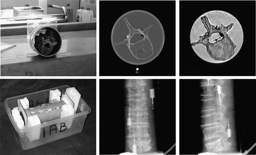
Image acquisition
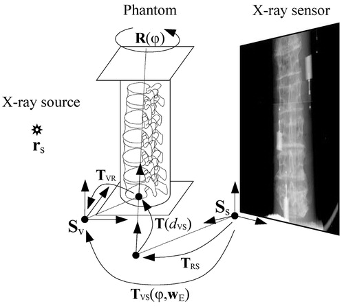
The CT image (, top center) was obtained using a General Electric HiSpeed CT/i scanner. Axial slices were taken with intra-slice resolution of 0.27×0.27 mm and inter-slice distance of 1 mm. For MR imaging, a Philips Gyroscan NT Intera 1.5 T scanner and T1 protocol (flip angle 90°, TR=3220 ms, TE=11 ms) was used (, top right). Axial slices were obtained with intra-slice resolution of 0.39×0.39 mm and inter-slice distance of 1.9 mm. The acquired MR image was retrospectively corrected for intensity inhomogeneity using the information minimization method Citation[8]. X-ray images () were captured by a Pixium 4600 digital X-ray detector (Trixell, Moirans, France). The detector had a 429×429 mm active surface, with pixel size of 0.143×0.143 mm and 14-bit dynamic range. To simulate C-arm acquisition, the X-ray source and sensor plane were fixed while the spine phantom was rotated on a turntable (). In this way, mechanical distortion due to gravitational force and other mechanical imperfections of the C-arms was avoided. By rotating the spine phantom around its long axis in 20° steps, 18 X-ray images were acquired. These images were filtered by a 3×3 median filter and then sub-sampled by a factor of two to remove dead pixel artifacts.
Figure 2. X-ray image acquisition.
Finding the centers of fiducial markers
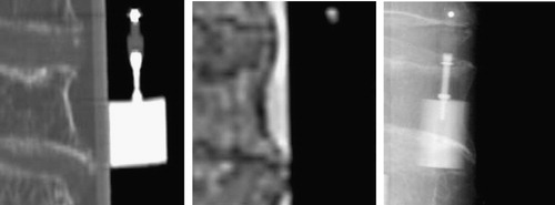
shows close-up views of fiducial markers in CT, MR and X-ray images. In all 3D and 2D images, a rough position pm of each fiducial marker was first defined manually. Next, an intensity threshold IT that separated the marker from the surrounding tissues was selected for each marker. Finally, the center pc of each marker was defined aswhere I(p) is the intensity at point p and Ω is a small neighborhood around point pm. By this method, centers of markers may be found with sub-pixel or sub-voxel accuracy Citation[9], Citation[10].
Figure 3. Close-up views of fiducial markers in CT (left), MR (center) and X-ray (right) images.
Let XCT and XMR be 3×6 matrices, each containing six 3D vectors representing the centers of fiducial markers found in CT and MR, respectively:where r=(x, y, z)T. Similarly, let Xφ be a 2×6 matrix containing six 2D vectors representing the centers of markers found in X-ray images obtained after rotating the phantom through φ degrees (φ=0°, 20°, … , 340°):
where p=(x, y)T.
Retrospective calibration of the X-ray setup
To be able to reconstruct the 3D positions of fiducial markers from their positions in 2D X-ray images, the acquisition setup () was retrospectively calibrated. Calibration required the determination of 12 geometrical parameters – 3 intrinsic wI and 9 extrinsic wE – denoted by calibration parameter vector w, w=(wI, wE). The intrinsic parameters wI=(xs, ys,zs) define the position of the X-ray source rs in the coordinate systems Ss of the sensor plane, and therefore define the projection PS(wI) of any 3D point described in the sensor coordinate system Ss to the 2D sensor plane. The extrinsic parameters wE describe the geometric relation between the rotating phantom and the X-ray system. Four parameters define the axis of rotation in the coordinate system Sv of the phantom. We have chosen the coordinate system of the CT volume for Sv. The axis of rotation is defined by the point (txv, tyv), which is the intersection of the axis with the x-y coordinate plane of Sv, and by rotation (ωxv, ωyv) of the axis around the x and y of Sv. Similarly, four parameters (txs, tys) and (ωxs, ωys) define the same axis of rotation in the coordinate system Ss of the X-ray sensor plane. The last parameter, necessary to determine the relation between Ss and Sv on the rotation axis, is distance dvs between the two points of intersection (txv, tyv) and (txs, tys). The extrinsic parameters wE=(txv, tyv, ωxv, ωyv, dvs, txs, tys, ωxs, ωys)T thus define the transformation TVS(φ, wE):
This transformation maps, for a given rotation φ of the phantom, any 3D point in coordinate system Sv to a 3D point in coordinate system Ss (). TVR is the transformation from coordinate system Sv to the axis of rotation; R(φ) is the rotation around the rotation axis; T(dvs) is the translation along the rotation axis; and TRS is the final transformation to the coordinate system Ss. For any rotation φ, the projection PVS(φ, w) of a 3D point defined in the coordinate system Sv to the 2D point lying in the sensor plane defined by Ss is obtained by applying the projection PS(wI) and the transformation TVS(φ, wE)
To retrospectively calibrate the X-ray acquisition system, we thus need to define 12 geometrical parameters w of the projection PVS(φ, w). For this purpose we have used centers X φ of fiducial markers found in the X-ray images and the corresponding centers XCT of markers found in the CT volume. The optimal calibration parameters w are the ones that bring the fiducial markers XCT in the CT volume to the best correspondence with the corresponding fiducial markers X φ in the X-ray images. To find the optimal parameters, we projected the centers of the fiducial markers XCT in the CT volume to the sensor plane and computed the root mean squared (RMS) distance Ecalib to the corresponding centers of fiducial markers X φ in the X-ray images:
where N and M stand for the number of fiducial markers and X-ray images, respectively, and Φ={φ1, φ2,…, φM} defines the X-ray images taken at different phantom rotations. To find the optimal calibration parameters w, we used nine X-ray images Φ={0°, 40°,…, 320°} and iterative optimization, which resulted in a minimum RMS distance (Ecalib) of 0.31 mm. The small RMS indicates that calibration was performed well and reflects the uncertainty of fiducial marker localization in CT and X-ray images.
Reconstruction of 3D markers
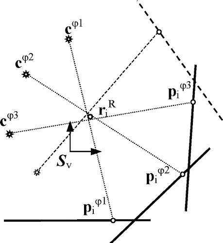
Once the X-ray acquisition system had been calibrated, the 3D positions of X-ray fiducial markers could be reconstructed from their positions in 2D X-ray images. The least-squares solution is used to obtain the 3D marker position Citation[11], as described below. Each point , representing the center of the ith fiducial marker in an X-ray image taken at rotation φ of the phantom, was back-projected to the X-ray source rs, which yielded the imaginary line
(). Line
, which defines the perspective projection of a 3D marker to the 2D X-ray plane, can be expressed in the coordinate system Sv of the phantom by mapping the X-ray source rs to point cφ:
and by expressing the line direction in Sv coordinates as
where rs and
are points defined in the sensor coordinate system Ss. A marker's 3D position
in the coordinate system Sv was reconstructed by minimizing the RMS distance Erec from point
to all lines
:
Figure 4. Reconstruction of 3D marker position. Due to the uncertainty of X-ray marker localization and X-ray setup calibration, the projection lines do not cross at the same point.
Reconstruction of the 3D positions of six fiducial markers from the nine X-ray images Φ={20°, 60°,…, 340°) which were not used for calibration yielded RMS values of less than 0.06 mm for each of the six markers. The positions of reconstructed fiducial markers were incorporated in the 3×6 matrix .
By using different sets of X-ray images for reconstruction and calibration, we were able to validate the calibration procedure. Small RMS values of 0.06 mm indicated that the uncertainty of fiducial marker localization in X-ray images was less than that in CT images and that calibration had been performed well. Therefore, the major source of calibration uncertainty is the uncertainty of fiducial marker localization in CT images, though its effect on calibration precision is obviously very small.
“Gold standard” registration and validation
After calibrating the X-ray acquisition system and reconstructing 3D markers XR from X-ray images, we were able to establish “gold standard” registration between X-ray and CT images and between X-ray and MR images in the coordinate system Sv of the phantom. This was achieved by a rigid 3D/3D transformation T that minimized the RMS distance Ereg between the reconstructed fiducial markers XR from X-ray images and the marker points XCT or XMR from CT and MR images, respectively:where ri stands for either
or
. The closed-form solution of this minimal RMS problem is known Citation[12], Citation[13]. Rigid transformation T can be decomposed to the rotation component R, represented by a 3×3 matrix, and translation vector t:
The optimal solution for the translation component is given as:where r¯R and r¯ stand for the mean positions of point sets XR and X, respectively, where set X is either XCT or XMR. The optimal solution for the rotation component is given as
A and B are two orthogonal matrices obtained by singular value decomposition (SVD) of the matrix
where D is a diagonal matrix and X¯R and X¯ are the point sets XR and X, centered at corresponding mean positions r¯R and r¯, respectively.
Rigid registration of point sets (XCT, XR) and (XMR, XR) resulted in a minimum RMS distance Ereg of 0.27 mm for CT and 0.44 mm for MR-to-X-ray registration. The higher RMS for MR than for CT can be attributed to three reasons: First, CT was used in calibration; second, intra- and inter-slice resolutions of the MR image were lower than those of the CT image, resulting in higher fiducial localization uncertainty; and the third, MR image suffered from non-rigid spatial distortion.
The minimum RMS distance Ereg is also known as the fiducial registration error (FRE) and can be used to evaluate the accuracy of point-based rigid registration Citation[7]. By knowing the FRE, we can determine the target registration error (TRE), which is the distance between the true, but unknown, position of the target and the target position obtained by registration. The expected TRE of a target point r can be estimated from FRE Citation[7]:
where fk is the RMS of the projections of the fiducial markers to the kth principal axis of marker configuration; dk is the projection of target point r to principle axis k; N is the number of fiducial markers; and FLE is the fiducial localization error obtained from the FRE:
Using the above formulation, we validated the “gold standard” registration by manually defining eight target points (four per pedicle) on each of the five vertebrae and computing the mean TRE for each vertebra. The results of “gold standard” validation for CT-to-X-ray and MR-to-X-ray registrations are given in . Expected TREs for the pedicles are less than 0.26 mm for CT-to-X-ray registration and less than 0.42 mm for MR-to-X-ray registration.
Table I. Expected RMS TREs for “gold standard” registration (in mm).
Publicly available “gold standard” data
The “gold standard” data and detailed information on how to use it are publicly available from the Department of Electrical Engineering, University of Ljubljana, Laboratory of Imaging Technologies web site (http://lit.fe.uni-lj.si/Downloads/downloads.asp). The image database consists of 18 X-ray images and 5 CT and 5 MR sub-volumes (). In the CT and MR images, cubic sub-volumes were manually defined, each containing a single vertebra, approximately one third of the neighboring vertebrae, and no fiducial markers. In each sub-volume the areas occupied by air and the plastic tube were manually masked and their intensities were replaced by the average intensity corresponding to water. The edges between water, the plastic tube, and air were thus almost eliminated. In this way, any rigid 3D/2D registration method evaluated using our “gold standard” data cannot take advantage of markers or edges that would not be present in actual clinical data. The markers in X-ray images, which were not excluded or “airbrushed”, may be considered as outliers, similar to the way that surgical tools would be in a clinical setting.
Figure 5. Transverse and sagittal views of CT (left) and MR (center) sub-volumes, and a lateral X-ray image (right).
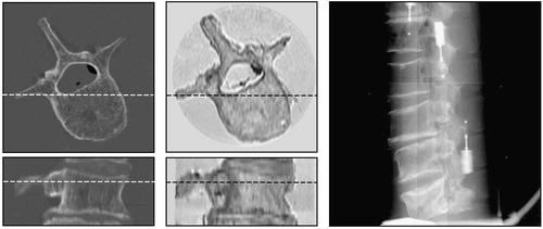
For each CT or MR sub-volume, the “gold standard” registration position, the coordinates of eight target points on the pedicles, and 450 randomly chosen starting positions around the “gold standard” registration position are also provided in the database. Details of the generation of starting positions have been previously published in reference Citation[14]. Furthermore, the data on our website contain the Matlab (MathWorks, Natick, MA) source code for analyzing registration results. The code allows calculation of TREs and estimation of capturing ranges from the results of 450 registrations per modality and vertebra. If different registration methods are to be objectively compared, it is not only important that the same image data sets be used, but equally important that the evaluation protocol, criteria for successful registration, and error metrics be the same. Otherwise, it will be difficult to place the results of a novel registration method in the context of previously published work.
Discussion and conclusion
Before an image-guided therapy (IGT) system is put into clinical use, its individual components must undergo rigorous validation. Prerequisites for validation of 3D/2D image registration, which is the crucial component of an IGT system, are standardization of validation methodology (including design of validation data sets), definition of the corresponding “gold standard” and its accuracy, a validation protocol, and design of validation metrics Citation[14]. A fair comparison of different registration techniques is possible only to a limited degree if standard validation methodology is not publicly available. Motivated by the lack of publicly available “gold standard” data for evaluation and comparison of different 3D/2D rigid registration methods, we have devised a lumbar spine phantom, obtained X-ray-to-CT and X-ray-to-MR “gold standard” registrations, and established the accuracy of these registrations. We are aware that there are surgical interventions and radiosurgical treatments of the spine for which markers are routinely inserted into the spine of the patient. Marker-based registered CT, MR and X-ray images of the spine can serve as a truly clinical “gold standard”, but are very difficult to obtain. Russakoff et al. Citation[15] reported on the evaluation of intensity-based 3D/2D spine image registration using clinical “gold standard data”. Unfortunately, to the best of our knowledge, their data are not publicly available. One problem with such a “gold standard” is the huge effort required to remove all traces of the implanted markers from images to avoid bias, i.e., to ensure that the evaluated registration method could not take advantage of markers that would not usually be present in images acquired for image-guided therapy.
Another approach to obtaining more realistic “gold standard” data is to overlay features segmented from clinical images on phantom images Citation[5]. Soft tissue, surgical instruments and other structures can be overlaid. Although our “gold standard” is not equivalent to the clinical “gold standard”, and no structures have been overlaid on our phantom images, we believe it is sufficiently realistic to allow fair evaluation and comparison of registration methods for image-guided therapy. Our database also contains MR images, and we believe this to be very valuable.
The X-ray acquisition system was calibrated retrospectively by matching the projections of CT markers with corresponding markers in X-ray images. Calibration with CT markers is generally superior to calibration with MR markers because CT offers better resolution and spatial stability. This observation was confirmed experimentally: CT-based calibration yielded a smaller calibration error Ecalib of 0.31 mm, compared with 0.47 mm when calibrating the X-ray system with MR data. CT-based calibration of the X-ray image acquisition setup already provides registration of CT to X-ray images, but does not provide any indices of registration accuracy. Therefore, we have reconstructed the 3D positions of markers from calibrated 2D X-ray images, allowing us to implement 3D/3D registration between the reconstructed markers and those found in CT and MR volumes. The result of such a registration reflected a) the uncertainty of marker localization in 2D X-ray images; b) the uncertainty of marker localization in 3D CT or MR images; c) the uncertainty of the X-ray acquisition calibration; and d) the uncertainty of marker reconstruction. The FRE of 3D/3D registration, which reflected all these uncertainties, was used to evaluate the TRE of the “gold standard” CT-to-X-ray and MR-to-X-ray registrations according to the theory developed in reference Citation[7].
The results presented in indicate that the “gold standard” registration is highly accurate and therefore useful for testing 3D/2D registration methods. However, it should be stressed that the expected TREs for CT-to-X-ray “gold standard” registration may possibly be a little larger than those in . This is because the same CT markers were used for both X-ray system calibration and CT-to-X-ray registration, which could have involved the same bias in calibration and registration. By acquiring a second CT scan at the time of image acquisition and using one for calibration and the other for validation bias could be eliminated. Nevertheless, if we assume that localization errors for CT markers are much smaller than those for MR markers, the expected TREs for CT-to-X-ray “gold standard” registration should be close to those shown in and certainly not larger than the TRE values for MR-to-X-ray registration.
We believe that, due to the lack of publicly available “gold standards” for 3D/2D rigid registration, the presented “gold standard” data will prove useful for the evaluation of newly developed methods and the comparison of existing registration methods.
Acknowledgments
The authors would like to thank L. Desbat, M. Fleute, R. Martin, F. Esteve and U. Vovk for their generous help and support in the image acquisitions. This work was supported by the IST-1999-12338 project, funded by the European Commission and by the Ministry of Education, Science and Sport, Republic of Slovenia, under grant P2-028.
References
- Galloway R L. The process and development of image-guided procedures. Ann Rev Biomed Eng 2001; 3: 83–108
- Lavallée S, Szeliski R. Recovering the position and orientation of free-form objects from image contours using 3D distance maps. IEEE Trans Pattern Anal Machine Intell 1995; 17: 378–90
- Guéziec A, Kazanzides P, Williamson B, Taylor R H. Anatomy-based registration of CT-scan and intraoperative X-ray images for guiding a surgical robot. IEEE Trans Med Imag 1998; 17: 715–28
- Lemieux L, Jagoe R, Fish D R, Kitchen N D, Thomas D GT. A patient-to-computed-tomography image registration method based on digitally reconstructed radiographs. Med Phys 1994; 21: 1749–60
- Penney G P, Weese J, Little J A, Desmedt P, Hill D LG, Hawkes D J. A comparison of similarity measures for use in 2-D-3-D medical image registration. IEEE Trans Med Imag 1998; 17: 586–95
- Jannin P, Fitzpatrick J M, Hawkes D J, Pennec X, Shahidi R, Vannier M W (2002) White paper: validation of medical image processing in image-guided therapy. Computer Assisted Radiology and Surgery. Proceedings of the 16th International Congress and Exhibition (CARS 2002), ParisFrance, June, 2002, H U Lemke, M W Vannier, K Inamura, A G Farman, K Doi, J HC Reiber. Springer, Berlin, 299–305
- Fitzpatrick J M, West J B, Maurer C R, Jr. Predicting error in rigid-body point-based registration. IEEE Trans Med Imag 1998; 17: 694–702
- Likar B, Viergever M A, Pernuš F. Retrospective correction of MR intensity inhomogeneity by information minimization. IEEE Trans Med Imag 2001; 20: 1398–1410
- Bose C B, Amir I. Design of fiducials for accurate registration using machine vision. IEEE Trans Pattern Anal Machine Intell 1990; 12: 1196–1200
- Chiorboli G, Vecchi G P. Comments on design of fiducials for accurate registration using machine vision. IEEE Trans Pattern Anal Machine Intell 1993; 15: 1330–2
- Siddon R L, Chin L M. 2-film brachytherapy reconstruction algorithm. Med Phys 1985; 12(1)77–83
- Arun K S, Huang T S, Blostein S D. Least-squares fitting of two 3-D point sets. IEEE Trans Pattern Anal Machine Intell 1987; 9(5)698–700
- Umeyama S. Least-squares estimation of transformation parameters between two point patterns. IEEE Trans Pattern Anal Machine Intell 1991; 13(4)376–80
- Tomazevič D, Likar B, Slivnik T, Pernuš F. 3-D/2-D registration of CT and MR to X-ray images. IEEE Trans Med Imaging 2003; 22(11)1407–16
- Russakoff D B, Rohlfing T, Ho A, Kim D H, Shahidi R, Adler J R, Maurer C R (2003) Evaluation of intensity-based 2D-3D spine image registration using clinical gold-standard data. Proceedings of Second International Workshop on Biomedical Image Registration (WBIR 2003), Philadelphia, PA, June, 2003, J C Gee, J BA Maintz, M W Vannier. Springer, Berlin, 151–160, Lecture Notes in Computer Science 2717