Abstract
Objective: The aim of this study was to find the proper location of the fluoroscopic imaging center in order to apply a CT-based 3D fluoroscopy matching navigation system in the pelvic and femoral regions.
Materials and methods: To simulate surgeries around the hip joint, a dry human pelvis and femur were used. A total of 16 fiducial markers, each consisting of a metal ball 1.5 mm in diameter, were fixed to the pelvis and femur. For the pelvis, the pubic symphysis, the acetabular fossa, and a site on the ilium 3 cm above the acetabular roof were selected as fluoroscopic imaging centers. For the proximal femur, the base of the femoral neck, the femoral shaft at the level of the lesser trochanter, and the inferior border of the great trochanter were selected as fluoroscopic imaging centers.
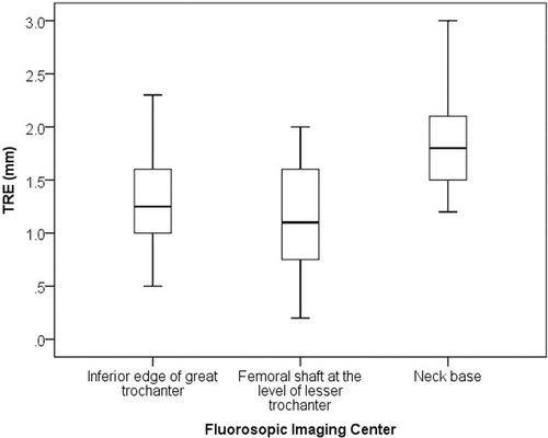
Results: Target registration error (TRE) differed significantly among the selected fluoroscopic imaging centers. The best mean TRE for the pelvis was 0.8 mm (range: 0.2 to 1.6 mm) with the imaging center on the ilium (3 cm above the acetabular roof). The best mean TRE for the proximal femur was 1.1 mm (range: 0.2 to 2.0 mm) with the imaging center on the femoral shaft at the lesser trochanter level.
Conclusion: Fluoroscopic imaging center location had a significant effect on the accuracy of the CT-based 3D fluoroscopy matching navigation system in the pelvic and femoral regions. The proper fluoroscopic imaging centers for CT-3D fluoroscopic matching were, for the pelvis, a site on the ilium 3 cm above the acetabular roof, and for the proximal femur, the femoral shaft at the level of the lesser trochanter.
Introduction
Three-dimensional (3D) fluoroscopic navigation systems using a mobile 3D C-arm equipped with an image intensifier (SIREMOBIL Iso-C3D, Siemens Medical Solutions, Erlangen, Germany), have been successfully validated mainly for spinal surgeries Citation[1–5]. These 3D fluoroscopic navigation systems make it possible to check the position of surgical instruments displayed on real-time computed tomography (CT)-like images while performing screw insertion or drilling. However, the drawback is that it is not possible to construct a surgical plan using the navigation systems prior to the acquisition of intraoperative 3D fluoroscopic images. Matching between preoperatively acquired CT imaging data and the intraoperative 3D fluoroscopic images would make it possible to perform surgeries using 3D fluoroscopic navigation systems based on 3D surgical plans constructed using the CT data. This could expand the use of 3D fluoroscopic navigation systems to include orthopedic surgeries of the pelvis and the upper and lower extremities Citation[6].
The application of flat panel detectors to the mobile C-arm represents a new technological development in 3D intraoperative imaging, significantly improving the quality of imaging with high resolution and broad dynamic range, and eliminating image distortion Citation[7–9]. It might be possible to successfully match high-quality intraoperative 3D images acquired with the flat panel detector-equipped C-arm to 3D CT images. We first tried to apply this CT-based 3D fluoroscopic matching navigation system to the pelvic and femoral regions. To apply the navigation system to large and long bones such as the pelvis and femur, it is necessary to find the proper location of the fluoroscopic imaging center to enable matching with 3D CT images, because of the limited image size with fluoroscopy Citation[6]. Sub-optimal location of the imaging center might increase registration error and decrease the accuracy of surgical procedures, resulting in a poor surgical outcome. It might also increase the surgical time, the fluoroscopic imaging time, and the risk of neurovascular injury.
The aims of the present study were therefore to assess the effect of imaging center location on the accuracy of this CT-based 3D fluoroscopy matching navigation system in the pelvic and femoral regions, and to find the proper location of the fluoroscopic imaging center.
Materials and methods
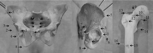
The navigation procedure was performed using a computer navigation system (Stryker Navigation System II Cart, Stryker, Kalamazoo, MI) and a mobile 3D C-arm equipped with a flat panel detector (Ziehm Vision FD Vario 3D, Ziehm Imaging, Nuremberg, Germany). To simulate surgeries around the hip joint, a dry human pelvis and femur of an adult male (Sawbones Worldwide, Pacific Research Laboratories, Inc., Vashon, WA) were used. They were free of significant visible deformity or pathology. Using titanium bone screws, a total of 16 fiducial markers (Cranial Marker Set, Stryker Leibinger, Freiburg, Germany) were fixed to predefined locations on the dry pelvis and femur (). Each marker in the Cranial Marker Set consists of a plastic male matrix pin containing a gold ball (1.5 mm in diameter) that engages the female matrix, whose inner thread can be screwed to the additional outer thread of the head of a 2.0-mm titanium bone screw. Four such markers were fixed to the acetabulum, one to each of its anterior, posterior, superior, and inferior edges. Four markers were fixed to the peripheral region of the pelvis, one to each of the following sites: the anterior superior iliac spine, the pubic tubercle, the sciatic notch, and the ischial tuberosity. Four markers were fixed to the femoral head and neck, one at each of the following locations: the superior, anterior, and inferior head-neck junctions, and the anterior cortex of the femoral neck. Finally, four markers were fixed to the proximal femur, one to each of the following sites: the tip of the great trochanter, the base of the lesser trochanter, and the anterior and lateral sides of the femoral shaft.
Figure 1. The dry human pelvis and femur with 16 fiducial markers, each consisting of a metal ball 1.5 mm in diameter. Four markers were fixed to the acetabulum: one to each of its anterior (1), posterior (2), superior (3), and inferior edges (4). Four markers were fixed to the peripheral region of the pelvis, one to each of the following sites: the anterior superior iliac spine (5), pubic tubercle (6), sciatic notch (7), and ischial tuberosity (8). Four markers were fixed to the femoral head and neck, one at each of the following locations: the superior (9), anterior (10), and inferior head-neck junctions (11), and the anterior cortex of the femoral neck (12). Finally, four markers were fixed to the proximal femur, one to each of the following sites: the tip of the great trochanter (13), the base of the lesser trochanter (14), and the anterior (15) and lateral sides of the femoral shaft (16).
CT images of the pelvis and femur were captured using a helical CT scanner (HiSpeed Advantage, GE Healthcare, Milwaukee, WI). The scanning parameters were as follows: slice thickness 1 mm, slice pitch 3, matrix size 512 × 512, and field of view 360 mm. Scan data were transferred into the navigation system.
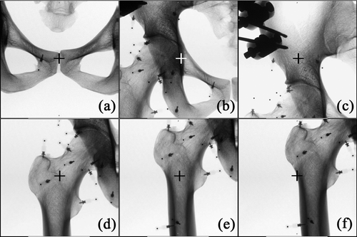
The dry pelvis and femur were placed in the lateral decubitus position on a Styrofoam board corresponding to an operating table. The board was supported 1 m above the floor by four tripods. The C-arm was placed on the left side of the table and the navigation system at the caudal end of the table (). Two dynamic reference trackers were attached; one to the ipsilateral pelvic crest and the other to the femoral shaft. Prior to the procedure, two directional C-arm images were obtained to determine the center of the scanned volume over the subject. Three locations in the pelvis and three in the proximal femur were selected as the imaging centers of the C-arm in order to determine appropriate imaging center locations for registration between the 3D fluoroscopic images and 3D CT images. For the pelvis, the pubic symphysis, the acetabular fossa, and a site on the ilium 3 cm above the acetabular roof were selected as imaging centers ( and ). For the proximal femur, the base of the femoral neck, the femoral shaft at the level of the lesser trochanter, and the inferior border of the great trochanter were selected as imaging centers ( and ).
Figure 2. Experimental set-up for the dry bone study. The C-arm was placed on the left side of the operating table, and the navigation system at the caudal end of the table. Surgery around the hip joint was simulated with a dry human pelvis and femur placed on the operating table in the lateral decubitus position.
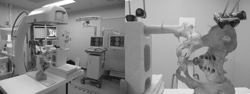
Figure 3. Left Fluoroscopic imaging centers of the pelvis for CT-3D fluoroscopy matching were the pubic symphysis (a), the acetabular fossa (b), and a site on the ilium 3 cm above the acetabular roof (c) (the imaging centers are indicated with crosshairs). Right: Fluoroscopic imaging centers of the proximal femur for CT-3D fluoroscopy matching were the base of the femoral neck (d), the femoral shaft at the level of the lesser trochanter (e), and the inferior border of the great trochanter (f).
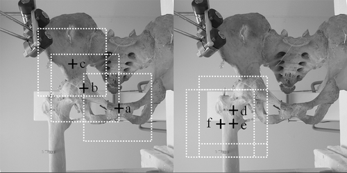
Figure 4. Upper row: Two-dimensional fluoroscopic images of the pelvis with the imaging center on the pubic symphysis (a), the acetabular fossa (b), and a site on the ilium 3 cm above the acetabular roof (c). Lower row: Two-dimensional fluoroscopic images of the proximal femur with the imaging center on the base of the femoral neck (d), the femoral shaft at the level of the lesser trochanter (e), and the inferior border of the great trochanter (f). The fluoroscopic imaging centers are indicated with crosshairs.
The C-arm was connected to the navigation system and calibrated by registering three points on the detector using a pointing device. Subsequently, 110 single images from a right cylindrical volume 12 cm in diameter and 12 cm in height were acquired during a 60-second automated orbital scan of 135°.
CT-3D fluoroscopy matching was performed by matching intraoperative 3D fluoroscopic images of each imaging center with preoperative CT datasets. First, the two sets of images were matched manually, then automatic volume registration was performed by maximization of mutual information Citation[10], Citation[11].
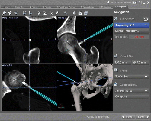
Virtual points were superimposed with the positions of metal marker images for subsequent measurements of accuracy. The tip of the navigation probe was then directed at each marker. The target registration error (TRE) was recorded and measured as the distance between the virtual tip of the navigation probe and the virtual points on the navigation display (). These procedures were repeated three times.
Figure 5. The navigation display showing multiplanar reconstructed views of CT images. The tip of the navigation probe was directed at each marker, and the TRE was measured as the distance between the virtual tip of the navigation probe and the marker on the navigation display.
The influence of the imaging center of the C-arm on TRE was assessed using the Kruskal-Wallis test. Statistical software (IBS SPSS Statistics 19, SPSS, Inc., Chicago, IL) was used for all statistical analyses. A 5% significance level was applied for all tests (P < 0.05).
Results
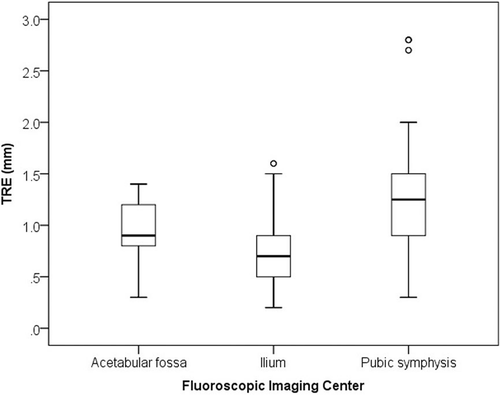
The mean TRE over the pelvis was 0.8 mm (range: 0.2 to 1.6 mm) with the imaging center on the ilium, 0.9 mm (range: 0.3 to 1.3 mm) with the center on the acetabular fossa, and 1.2 mm (range: 0.3 to 2.8 mm) with the center on the pubic symphysis. TRE differed significantly among the three imaging centers (P < 0.0001) (), with the site on the ilium 3 cm above the acetabular roof giving the smallest error.
Figure 6. Box-whisker plots showing target registration error over the pelvis for each fluoroscopic imaging center. There were significant differences in TRE among the imaging centers.
The mean TRE over the proximal femur was 1.1 mm (range: 0.2 to 2.0 mm) with the imaging center on the femoral shaft at the level of the lesser trochanter, 1.3 mm (range: 0.5 to 2.3 mm) with the center on the inferior edge of the great trochanter, and 1.8 mm (range: 1.2 to 3.0 mm) with the center on the base of the femoral neck. TRE differed significantly among the three imaging centers (P < 0.0001) (), with the femoral shaft at the level of the lesser trochanter giving the smallest error.
Discussion
The accuracy of image-to-image registration depends in part on the shape of the bones. In addition, it is necessary to reduce the effect of adjacent bones that are outside the target, although in most cases the target of treatment is located near articular joints. It is therefore important to determine the proper imaging area of 3D fluoroscopic imaging for CT-3D fluoroscopy matching of the pelvic and femoral regions.
We selected three locations as candidates for the fluoroscopic imaging center of the pelvis in relation to the femur. To eliminate the effect of the femur on CT-3D fluoroscopic matching of the pelvis, we selected the pubic symphysis and ilium as imaging centers so that the fluoroscopic imaging volume would include as little of the femur as possible. The fluoroscopic imaging volume centered on the pubic symphysis excluded the femur completely. To avoid metal artifact from the dynamic reference tracker fixed to the ipsilateral pelvic crest, we set the imaging center of the ilium at 3 cm above the acetabular roof. It was assumed that the half of the femoral head included in the fluoroscopic imaging volume would not affect registration accuracy. We considered the location 3 cm above the acetabular roof to be a proper location centered on the ilium, because the diameter of the femoral head ranged from approximately 3.5 cm to 5.5 cm Citation[12], Citation[13]. To assess the effect of the femur on CT-3D fluoroscopic matching of the pelvis, we selected the acetabular fossa as the imaging center, since the corresponding fluoroscopic imaging volume included the largest area of the proximal femur compared to that for the other two imaging centers. The acetabular fossa showed the largest TRE, indicating that the effect of the femur on CT-3D fluoroscopic matching of the pelvis was significant. The site on the ilium 3 cm above the acetabular roof showed the smallest TRE, indicating that it is important to set the imaging center on the hemi-pelvis rather than to completely exclude the femur from the imaging volume.
Three locations were selected as candidates for the fluoroscopic imaging center of the femur in relation to the pelvic bone. To eliminate the effect of the pelvic bone on CT-3D fluoroscopic matching of femur, we translated the imaging center in the distal and lateral directions from the base of the femoral neck. The fluoroscopic imaging volume centered on the femoral shaft at the level of the lesser trochanter included part of the pelvis, while that centered on the inferior edge of the great trochanter excluded the pelvic bone completely. As a result, the neck base showed the largest TRE, indicating that the effect of the pelvic bone on CT-3D fluoroscopic matching of the femur was significant. However, the femoral shaft at the level of the lesser trochanter showed the smallest TRE among the three sites. This indicated that it is important to set the imaging center on the proximal femoral bone rather than exclude the pelvic bone from the imaging volume completely.
In this study, we confirmed that it is possible to perform surgeries of the pelvic and femoral regions using a CT-3D fluoroscopy matching navigation system with accuracy within 2 mm. This system has the advantages of both CT-based navigation and 3D fluoroscopic navigation Citation[6]. It enables surgeons to create a 3D surgical plan using preoperatively acquired 3D-CT images, which is important for safety and accuracy in a variety of orthopedic surgical procedures Citation[14–17]. Hence, it may be possible to expand the use of 3D fluoroscopic navigation to include some trauma surgeries, tumor resections, arthroplasties, and osteotomies of the pelvis and femur Citation[6]. Image-to-patient registration using the 3D fluoroscopy navigation system might enable the registration procedure to be completed before making a major surgical incision. This could decrease the invasiveness of procedures and avoid technical errors associated with manual registration of intraoperative anatomic structures. These advantages could also enable the extension of the use of CT-based navigation to various novel, less invasive surgeries of the pelvic and femoral regions Citation[6].
There are two possible limitations in the present study. The first is that another location not evaluated in the study might give even better accuracy. We selected three potential locations for the imaging center on the pelvis and femur based on bony landmarks because the imaging center location should be easy for radiology technologists to find during preparation. In addition, in real situations, there are anatomical variations in the size and the shape of the bones. Thus, we did not evaluate whether a minor adjustment of the imaging center in 1 cm increments (for example) could have a significant effect on registration accuracy. The other limitation is that this experimental study using dry bones did not assess the effect of soft tissues or bone quality. Abundant soft tissue in overweight and obese patients and poor bone quality in patients with osteoporosis might decrease the quality of the 3D fluoroscopic images, which could affect the accuracy of CT-3D fluorosopy matching navigation. Further studies would be required to address these points.
In conclusion, imaging center location had a significant effect on the accuracy of the CT-based 3D fluoroscopy matching navigation system in the pelvic and femoral regions. The proper fluoroscopic imaging centers for CT-3D fluoroscopic matching were, for the pelvis, a site on the ilium 3 cm above the acetabular roof, and for the proximal femur, the femoral shaft at the level of the lesser trochanter.
Declarations of interest: This study was supported by a Grant-in-Aid for Scientific Research (KAKENHI) from the Japan Society for the Promotion of Science (No. 22791377, Grant-in-Aid for Young Scientists (B)). No benefits in any form have been received or will be received from a commercial party related directly or indirectly to the subject of this article.
References
- Ito Y, Sugimoto Y, Tomioka M, Hasegawa Y, Nakago K, Yagata Y. Clinical accuracy of 3D fluoroscopy-assisted cervical pedicle screw insertion. J Neurosurg Spine 2008; 9: 450–453
- Hott JS, Papadopoulos SM, Theodore N, Dickman CA, Sonntag VK. Intraoperative Iso-C C-arm navigation in cervical spinal surgery: Review of the first 52 cases. Spine (Phila Pa 1976) 2004; 29: 2856–2860
- Hott JS, Deshmukh VR, Klopfenstein JD, Sonntag VK, Dickman CA, Spetzler RF, Papadopoulos SM. Intraoperative Iso-C C-arm navigation in craniospinal surgery: the first 60 cases. Neurosurgery 2004; 54: 1131–1136, discussion 6–7
- Rajasekaran S, Vidyadhara S, Ramesh P, Shetty AP. Randomized clinical study to compare the accuracy of navigated and non-navigated thoracic pedicle screws in deformity correction surgeries. Spine (Phila Pa 1976) 2007; 32: E56–E64
- Nakashima H, Sato K, Ando T, Inoh H, Nakamura H. Comparison of the percutaneous screw placement precision of isocentric C-arm 3-dimensional fluoroscopy-navigated pedicle screw implantation and conventional fluoroscopy method with minimally invasive surgery. J Spinal Disord Tech 2009; 22: 468–472
- Stöckle U, Schaser K, König B. Image guidance in pelvic and acetabular surgery – expectations, success and limitations. Injury 2007; 38: 450–462
- Kalender WA, Kyriakou Y. Flat-detector computed tomography (FD-CT). Eur Radiol 2007; 17: 2767–2779
- Reichardt B, Sarwar A, Bartling SH, Cheung A, Grasruck M, Leidecker C, Bredella MA, Brady TJ, Gupta R. Musculoskeletal applications of flat-panel volume CT. Skeletal Radiol 2008; 37: 1069–1076
- Takao M, Yabuta K, Nishii T, Sakai T, Sugano N. Accuracy of a 3D fluoroscopic navigation system using a flat-panel detector-equipped C-arm. Comput Aided Surg 2011; 16: 234–239
- Maes F, Collignon A, Vandermeulen D, Marchal G, Suetens P. Multimodality image registration by maximization of mutual information. IEEE Trans Med Imaging 1997; 16: 187–198
- Wells WM 3rd, Viola P, Atsumi H, Nakajima S, Kikinis R. Multi-modal volume registration by maximization of mutual information. Med Image Anal 1996; 1: 35–51
- Nakahara I, Takao M, Sakai T, Nishii T, Yoshikawa H, Sugano N. Gender differences in 3D morphology and bony impingement of human hips. J Orthop Res 2011; 29: 333–339
- Maruyama M, Feinberg JR, Capello WN, D’Antonio JA. The Frank Stinchfield Award: Morphologic features of the acetabulum and femur: Anteversion angle and implant positioning. Clin Orthop Relat Res 2001; 393: 52–65
- Noble PC, Sugano N, Johnston JD, Thompson MT, Conditt MA, Engh CA, Sr, Mathis KB. Computer simulation: How can it help the surgeon optimize implant position?. Clin Orthop Relat Res 2003; 417: 242–252
- Sugano N, Ohzono K, Nishii T, Haraguchi K, Sakai T, Ochi T. Computed-tomography-based computer preoperative planning for total hip arthroplasty. Comput Aided Surg 1998; 3: 320–324
- Wong KC, Kumta SM, Chiu KH, Antonio GE, Unwin P, Leung KS. Precision tumour resection and reconstruction using image-guided computer navigation. J Bone Joint Surg Br 2007; 89: 943–947
- Sariali E, Mouttet A, Pasquier G, Durante E, Catone Y. Accuracy of reconstruction of the hip using computerised three-dimensional pre-operative planning and a cementless modular neck. J Bone Joint Surg Br 2009; 91: 333–340

