Abstract
Background and purpose It is controversial whether the transverse acetabular ligament (TAL) is a reliable guide for determining the cup orientation during total hip arthroplasty (THA). We investigated the variations in TAL anatomy and the TAL-guided cup orientation.
Methods 80 hips with osteoarthritis secondary to hip dysplasia (OA) and 80 hips with osteonecrosis of the femoral head (ON) were examined. We compared the anatomical anteversion of TAL and the TAL-guided cup orientation in relation to both disease and gender using 3D reconstruction of computed tomography (CT) images.
Results Mean TAL anteversion was 11° (SD 10, range –12 to 35). The OA group (least-square mean 16°, 95% confidence interval (CI): 14–18) had larger anteversion than the ON group (least-square mean 6.2°, CI: 3.8 – 7.5). Females (least-square mean 20°, CI: 17–23) had larger anteversion than males (least-square mean 7.0°, CI: 4.6–9.3) in the OA group, while there were no differences between the sexes in the ON group. When TAL was used for anteversion guidance with the radiographic cup inclination fixed at 40°, 39% of OA hips and 9% of ON hips had more than 10° variance from the target anteversion, which was 15°.
Interpretation In ON hips, TAL is a good guide for determining cup orientation during THA, although it is not a reliable guide in hips with OA secondary to dysplasia. This is because TAL orientation has large individual variation and is influenced by disease and gender.
Malalignment of the acetabular cup may lead to dislocation (Jolles et al. Citation2002, Shon et al. Citation2005), accelerated wear or breakage of the bearing, and component loosening (Kennedy et al. Citation1998). The use of a mechanical guide for cup implantation may give inaccurate results because of pelvic rotation on the operating table (Sugano et al. Citation2007, Minoda et al. Citation2010).
Recently, the transverse acetabular ligament (TAL), which bridges the acetabular notch (Löhe et al. Citation1996) as part of the acetabular labrum, has been reported to be useful for determining proper orientation of the acetabular components (Archbold et al. Citation2006, Citation2008, Pearce et al. Citation2008, Kalteis et al. Citation2011). TAL-guided cup orientation has been reported to guide the cup placement within Lewinnek’s safe zone (Lewinnek et al. Citation1978). Other studies have shown that the TAL is not a reliable guide (CitationEpstein et al. 2010, Viste et al. Citation2011). We hypothesized that these divergent results could be explained by individual anatomical variation; in addition, orientation of the TAL may be affected by hip disease and gender. Furthermore, cup orientation is influenced by sagittal pelvic tilt (Nishihara et al. Citation2003, DiGioia et al. Citation2006).
We determined (1) the variation in the TAL orientation and the influence of hip disease and gender on this variation, (2) the reliability of using the TAL for guiding cup orientation, and (3) the influence of pelvic tilt on the TAL-guided cup orientation, using computed tomography (CT) scan and computer simulation.
Patients and methods
We studied 80 hips in 80 patients with osteoarthritis secondary to Crowe group 1 (Crowe et al. Citation1979) hip dysplasia (OA patients) and 80 hips in 80 patients with osteonecrosis of the femoral head (ON patients) who underwent preoperative CT and primary THA between April 2004 and March 2011. There were 38 males and 42 females in each group. Mean age was lower in the ON group than in the OA group (). The OA hips had anatomical abnormalities due to hip dysplasia whereas the ON hips had normal acetabular anatomy.
Table 1. Demographic data a
Preoperatively, the entire pelvis was imaged for computer navigation using a helical CT scanner (High-Speed Advantage; General Electric, Milwaukee, WI) with a 3-mm slice pitch and 1-mm thickness. 3D anatomical measurements and cup placement simulation were performed using the CT images and 3D template software (Japan Medical Material, Osaka, Japan).
We used 2 types of pelvic coordinate systems to measure the TAL orientation and cup angles. The anatomical coordinate system (ACS) is defined by the anterior pelvic plane (APP) that passes through the anterior superior iliac spines and the midpoint between the pubic tubercles (Lewinnek et al. Citation1978). Unit vectors of this anatomical system were defined as follows: the x-axis was the mediolateral axis parallel to the line passing through the anterior superior iliac spines; the z-axis was the anteroposterior axis perpendicular to the APP; and the y-axis was the craniocaudal axis perpendicular to the x- and z-axes. The other pelvic coordinate system used was functional and was derived from the anatomical sagittal pelvic tilt with the patient in the supine position (Sugano Citation2003, Miki et al. Citation2007, Sugano et al. Citation2007). Unit vectors of the functional pelvic coordinate system (FCS) were defined as follows: the x-axis was the same as in the ACS; the z-axis was perpendicular to the CT table; and the y-axis was perpendicular to the anteroposterior and mediolateral axes. The mean APP sagittal tilt (pelvic tilt) was 5.7° (SD 6.7, range: –20° to 20°), and there was no statistically significant difference in pelvic tilt between the OA and ON groups (5.9° for OA, SD 7.1; 5.6° for ON, SD 6.4; p = 0.8, Student’s t-test).
The TAL was defined as the line visualized on CT scan extending between the posteroinferior and anteroinferior edges of the acetabular rim, bridging the acetabular notch. First, the acetabular notch was identified at the inferior acetabulum on the opening plane. Next, the TAL was drawn as the line described above, at the inferior acetabulum on the opening plane. Then, the inclination for cup placement was guided by the acetabular rim (Archbold et al. Citation2006) and the cup was virtually placed to be parallel with the TAL plane in order to fit an adequate cup size to the acetabulum. Finally, we measured TAL anteversion in accordance with the anatomical definition, and cup inclination and anteversion according to the radiographic definitions (Murray Citation1993), based on the ACS and the FCS, respectively ().
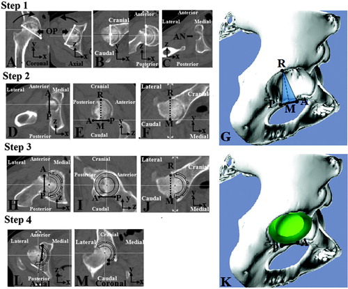
Figure 1 Definition of TAL and TAL-guided cup placement. Step 1: The opening plane (OP), which was fitted to the opening plane of the acetabulum, was settled. This plane contained two lines. A. The first line (white line on the coronal plane) was drawn from the tear drop to the upper acetabular rim edge at the level of the femoral head center. The second line (white line on the axial plane) was drawn from the anterior edge to the posterior edge of acetabular rim at the level of the femoral head center. B. The OP was rotated to be parallel with the y-axis in the coronal plane and parallel with the z-axis in the axial plane. C. The acetabular notch (AN) was identified at the inferior acetabulum. Step 2: The TAL (the black line) was defined as the AP line between the anteroinferior edge; point A and posteroinferior edge; point P of the acetabular rim in the craniocaudal view (D) and lateral view (E). F. Intersection; point R of acetabular rim edge with the vertical plane containing the TAL was settled in the anteroposterior view of the TAL. Line RM, the guide for cup inclination, was drawn from the TAL midpoint M to point R. The TAL plane containing lines AP and RM was settled. G. 3D image of the TAL and the TAL plane. Step 3: The equatorial plane of the cup was virtually placed so as to be parallel with line AP in the craniocaudal view (H), lateral view (I), and line RM in the anteroposterior view (J). K. 3D image of the cup placement. Step 4: Anatomical anteversion of the TAL in the ACS and the FCS and radiographic cup orientation guided by the TAL in the ACS and the FCS was measured in the axial view (L) and the coronal view (M).
We compared the TAL alignment between the bony points of the TAL insertion on the first CT and the actual ligament insertion marked by stainless bead markers on the second CT in 6 cadaver hips to evaluate the accuracy of the TAL definition measured with the CT scan (). We measured the anteversion of the line between the beads on the second CT and compared this with the TAL alignment measured from the bony points on the first CT. In both measuring methods, we measured the anteversion in the ACS. To evaluate the influence of the short length of the TAL on the anteversion measurement, we recorded the TAL length using cadaveric hips. Moreover, we investigated the intraobserver reliability, the interobserver reliability, and the root-mean-square error (RMSE) of this measuring method using bony points in 10 randomly selected hips out of the 160 available hips.
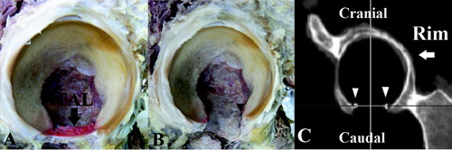
Figure 2. Verification of the TAL alignment measurement method. We verified the measurement method using cadaveric hips. A. The TAL and acetabulum were exposed. B. The beads were attached at the anterior and posterior insertion of the TAL. C. CT images before and after attachment of the beads on the posteroinferior and anteroinferior edges of the acetabular rim were obtained. We compared the anteversion of the line between the bony points on the first CT and the line between the beads on the second CT.
To determine the influence of the variability of acetabular abduction angle on the simulated cup orientation, we measured cup anteversion in the FCS when the radiographic inclination of the cup was fixed at 30°, 40°, and 50°, while cup anteversion was determined in accordance with the TAL. We determined the number of outliers that showed a difference of more than 10° from the target orientation, which was 40° of radiographic inclination and 15° of radiographic anteversion in the FCS. We also compared the numbers of anteversion outliers when the cup inclination was fixed at 30°, 40°, and 50°.
In addition, we compared rates of outliers in cup orientation according to hip disease (OA, ON), gender, and the pelvic coordinate system used (ACS or FCS).
This study was approved by our hospital institutional review board on December 11, 2011 with registration number 11201.
Statistics
Interclass correlation efficient (ICC) was used to determine the accuracy of the way of measurement of TAL alignment. Pearson’s correlation coefficient was used to determine the influence of TAL length on the way of measurement of TAL alignment. Student’s t-test was used to determine whether there were significant differences concerning age, BMI, and pelvic tilt between the OA group and the ON group. Analysis of covariance (ANCOVA) was used to determine whether significant differences existed concerning TAL alignment between the OA group and the ON group and between males and females, and concerning cup orientation between the OA group and the ON group. The results of the analysis by ANCOVA were adjusted for age and BMI. The Wilcoxon signed-ranks test was used to determine whether there were significant differences concerning TAL alignment between by measuring in the ACS and by measuring in the FCS. Statistical significance was assumed when p < 0.05.
Statistical analyses were done using SPSS software version 19 and SAS for Windows version 9.1.3.
Results
The mean measure of anteversion variance between the TAL bony points as defined by the first CT and the actual ligament insertion marked by the beads on the second CT in cadaveric hips was –1.8° (SD 0.9, range: –2.4 to –0.4). The accuracy was 0.89 (CI: –0.04 to 0.98; p = 0.001) for this interclass correlation, and 1.3 for the RMSE. The mean TAL length was 21 mm (SD 2.4). There were no significant correlations between the TAL length and the difference in degrees of anteversion (Pearson’s correlation coefficient r = 0.17; p = 0.8).
The intraobserver interclass correlation was 0.95 (CI: 0.82–0.98; p < 0.001) and the RMSE was 1.3. The interobserver interclass correlation was 0.93 (CI: 0.77–0.98; p < 0.001) and the RMSE was 1.8.
The OA group had statistically significantly greater measures of anteversion than the ON group, and females in the OA group had significantly greater anteversion than males ( and ). The mean anatomical TAL anteversion was 11° (SD 10, range: –12 to 35) in the ACS and 11° (SD 10, range: –11 to 34) in the FCS. 23 of 160 hips (14%) measured in ACS and 20 of 160 hips (13%) measured in the FCS had retroverted TALs. Anteversion in the OA group was statistically significantly greater than in the ON group, as measured in both the ACS (least-square mean 16°, CI: 14–18 for OA; least-square mean 5.7°, CI: 3.8–7.5 for ON; p < 0.001, ANCOVA test) and in the FCS (least-square mean 15°, CI: -13 to 17° for OA; least-square mean 5.9°, CI: 3.9–7.8 for ON; p < 0.001) (). The mean anatomical TAL anteversion was statistically significantly greater in the OA females than in OA males, in both the ACS (least-square mean 20°, CI: 17–23 for females; least-square mean 11°, CI: 8–14 for males; p < 0.001) and in the FCS (least-square mean 19°, CI: 16–22 for females; least-square mean 9.3°, CI: 5.8–13 for males; p < 0.001), whereas there was no significant difference between the males and females with ON ().
Table 2. Anatomical anteversion of the TAL a
Table 3. Sex differences in anatomical TAL anteversion, measured in degrees a
TAL-guided cup orientation resulted in 127 outliers of 160 (79%) as measured in the ACS, and 123 outliers of 160 (77%) as measured in the FCS. Anteversion and inclination of the cup were statistically significantly greater in the OA group than in the ON group (p < 0.001) (). Inclination was more than 50° as measured in the ACS in 77 of 80 OA hips (96%) and 47 of 80 ON hips (59%). This was true for 78 of 80 OA hips (98%) and 40 of 80 ON hips (50%) measured in the FCS. When measuring with the ACS, a difference of greater than 10° from the target angle was evident for 78 of 80 OA hips (98%) and 49 of 80 ON hips (61%). However, when measuring with the FCS, this was true for 78 of 80 OA hips (98%) and for 45 of 80 ON hips (56%) (). When the cup radiographic inclination was fixed at 40° and the TAL was used for anteversion guidance, least-square mean cup anteversion was 23.2° (CI: 22–25) in the OA group and 14.4° (CI: 13–16) in the ON group when measured in the FCS (). A more than 10° difference from the target angle was found for 31 of 80 OA hips (39%) and 7 of 80 ON hips (9%). When the radiographic inclination of the cup was fixed at 30°, 27 of 80 OA hips (34%) and 8 of 80 ON hips (10%) showed more than 10° difference from the target angle. When the radiographic inclination of the cup was fixed at 50°, 33 of 80 OA hips (41%) and 7 of 80 ON hips (9%) hips showed a more than 10° difference from the target angle. There were no differences in rates of anteversion outliers for cup inclinations of 30°, 40°, and 50°.
Table 4. Radiographic definition of TAL-guided cup orientation, measured in degrees a
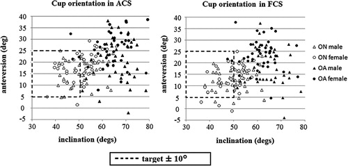
Figure 3. Scatter diagram of cup orientation measurements in the ACS and FCS. In the ACS, 78 of 80 OA hips (98%) and 49 of 80 ON hips (61%) had a more than 10° difference from our target cup orientation (dotted line area). In the FCS, 78 of 80 OA hips (98%) and 45 of 80 ON hips (56%) had a more than 10° difference from the target cup orientation.
TAL-guided cup orientation was influenced by pelvic sagittal tilt. Cup anteversion measured with the ACS was greater than that measured in the FCS in the OA group (p < 0.001, Wilcoxon signed-rank test) and in the ON group (p < 0.001). This was also true for cup inclination (p < 0.001 for both groups). Differences in cup anteversion between the ACS and FCS were more than 5° for 48 of the 160 hips (30%).
Discussion
Cup orientation is one of the critical factors relating to THA longevity and stability after THA (Amstutz et al. Citation1975, Widmer and Zurfluh Citation2004). Mechanical guides (Minoda et al. Citation2010) are the most popular instruments for determining cup orientation; however, the accuracy achieved with their use is not high enough to eliminate outliers—those not within 10° of the target angle. The TAL has been reported by several authors to provide an anatomical landmark for referencing cup orientation during THA (Archbold et al. Citation2006, Citation2008, Pearce et al. Citation2008, Mihalko et al. Citation2009). TAL-guided acetabular reaming and positioning has been reported to produce a postoperative dislocation rate of 0.6%without radiographic measurements of cup orientation (Archbold et al. Citation2006). Although several reports have validated the value of the TAL to provide cup guidance, each report used a different measurement methodology (). TAL-guided acetabular component position has been reported to be implanted in 87 to 100% within Lewinneck’s safe zone (Lewinnek et al. Citation1978) by radiographic definition in both cadaveric and clinical studies (Pearce et al. Citation2008, Kalteis et al. Citation2011). However, it has also been reported that the TAL is not a reliable guide for cup and anatomical orientation (CitationEpstein et al. 2010, Viste et al. Citation2011). Discrepancies among reports of TAL-guided cup placement accuracy may have been the result of individual anatomical variability, which can be influenced by disease, gender, and the pelvic sagittal tilt—as noted in the present study.
Table 5. Comparison of availability of TAL in THA
Our study is limited by the fact that we did not identify the TAL macroscopically, but approximated its position using the bony points of the rim, because it has been reported that the TAL forms a bridge across the acetabular notch and continues to the outer edge of the acetabulum and the base of the acetabular labrum (Löhe et al. Citation1996). Moreover, the TAL definition in our study had high accuracy because of high interclass correlation and RSME when comparing 2 CT images in cadaveric hips, and because of the good intra- and interobserver error values using 3D template software. Also, we used the bony rim of the acetabulum as the inclination guidance of the cup. Although the labrum had been used for cup guidance in a past study (Archbold et al. Citation2008), we did not use the labrum. This is because the labrum was resected in our patients.
We found that TAL anteversion had individual variations, which can be attributed to disease and gender. In previous studies, the mean TAL anatomical anteversion ranged from 1.9° to 24°, and the rate of retroverted TAL ranged from 0% to 36% in hip labral tear studies and normal cadaveric studies (Archbold et al. Citation2008, Viste et al. Citation2011). The anatomical TAL anteversion in our study was consistent with these previous reports. Although differences in acetabular anteversion between normal hips and OA hips, and between the sexes, have been reported previously (Anda et al. Citation1991, Jacobsen et al. Citation2005, Nakahara et al. Citation2010), we have not found any reports regarding TAL orientation. Females had larger anatomical anteversion than males at the level of the femoral head center in the normal hip group, and differences in acetabular anteversion between sexes may have influenced the variation in range of motion in previous studies (Nakahara et al. Citation2010).
To determine the accuracy of using the TAL and the acetabular rim to guide cup placement, we measured cup orientation in secondary OA and ON groups. In both groups, cup inclination was more than 50° in 124 hips (69%). Even though cup inclination was fixed at 40° by radiographic definition in the FCS, 39% of the OA hips and 9% of the ON hips had a greater than 10° difference from the target angle. There were no differences between rates of anteversion outliers when inclination was fixed at 30°, 40°, or 50°. Cup placements ranging from 28% to 78% of the total have been identified as outliers from Lewinnek’s safe zone when using mechanical guides (Hassan et al. Citation1998, Digioia et al. Citation2002, Saxler et al. Citation2004, Kalteis et al. Citation2006, Minoda et al. Citation2006, Callanan et al. Citation2011). In addition, TAL-guided implantation of acetabular components has been found to be no more accurate for cup positioning than the use of the mechanical guide by radiographic definition (CitationEpstein et al. 2010). TAL guidance might be useful in hips with normal anatomy such as those with ON, femoral neck fracture, or rheumatoid arthritis. On the other hand, in hips with OA secondary to dysplasia, TAL guidance has been found to have no advantage over the mechanical guide method; even though the cup was placed in Lewinnek’s zone, dislocation occurred (Lewinnek et al. Citation1978). To avoid impingement when patients have a large range of movement, the cup should be placed in a narrow range, and the combined stem and cup anteversion should be considered (Widmer and Zurfluh Citation2004). However, in cup placement guided by the TAL, the influence of femoral anteversion is ignored. Considering that 39% of the outliers exist even beyond the Lewinnek’s zone, the TAL is not a reliable guide for determination of cup orientation in OA hips secondary to dysplasia.
The sagittal pelvic tilt also has an influence on cup orientation (Kalteis et al. Citation2009). The TAL-guided anteversion in the ACS was greater than that with FCS in the OA group, and less than that in the ON group. Although some surgeons have claimed that the anterior pelvic plane was used as a landmark for cup orientation during THA (Widmer and Zurfluh Citation2004), the sagittal tilt in the anterior pelvic plane differs between individuals and changes with posture (Nishihara et al. Citation2003, DiGioia et al. Citation2006). Similarly, we found that the TAL has individual variation influenced by the pelvic sagittal tilt, as well as by disease and gender.
In conclusion, cup placement guided by the TAL is subject to individual variation related to disease and gender, and is influenced by sagittal pelvic tilt, resulting in 39% anteversion outliers (OA) and 9% anteversion outliers (ON) of more than 10° from our target orientation. Although TAL may be a good guide in hips with normal anatomy (including ON hips), TAL is not a reliable guide in hips with OA secondary to dysplasia for determining optimal cup orientation during THA.
HA: planning, data collection, data analysis, and writing and editing of manuscript. TS: planning, data collection, data analysis, and writing and editing of manuscript. TH: statistics. MT: data collection. TN: data collection. NN: data collection. NS: planning, data collection, data analysis, confirmation of the data accuracy, and editing of manuscrtipt.
The authors thank Dr Hideki Yoshikawa for helpful advice. The authors also thank Mr Wataru Yamanashi, Dr Satoru Tamura, and Dr Satoshi Nakasone for technical support.
No competing interests declared.
- Amstutz HC, Lodwig RM, Schurman DJ, Hodgson AG. Range of motion studies for total hip replacements. A comparative study with a new experimental apparatus. Clin Orthop 1975; (111): 124-30.
- Anda S, Terjesen T, Kvistad KA. Computed tomography measurements of the acetabulum in adult dysplastic hips: which level is appropriate? Skeletal Radiol 1991; 20 (4):267-71.
- Archbold HA, Mockford B, Molloy D, McConway J, Ogonda L, Beverland D. The transverse acetabular ligament: an aid to orientation of the acetabular component during primary total hip replacement: a preliminary study of 1000 cases investigating postoperative stability. J Bone Joint Surg (Br) 2006; 88 (7): 883-6.
- Archbold HA, Slomczykowski M, Crone M, Eckman K, Jaramaz B, Beverland DE. The relationship of the orientation of the transverse acetabular ligament and acetabular labrum to the suggested safe zones of cup positioning in total hip arthroplasty. Hip Int 2008; 18 (1): 1-6.
- Callanan MC, Jarrett B, Bragdon CR, Zurakowski D, Rubash HE, Freiberg AA, Malchau H. Risk factors for cup malpositioning: quality improvement through a joint registry at a tertiary hospital. Clin Orthop 2011; (469) (2): 319-29.
- Crowe JF, Mani VJ, Ranawat CS. Total hip replacement in congenital dislocation and dysplasia of the hip. J Bone Joint Surg (Am) 1979; 61 (1): 15-23.
- Digioia AM 3rd, Jaramaz B, Plakseychuk AY, Moody JE Jr, Nikou C, Labarca RS, Levison TJ, Picard F. Comparison of a mechanical acetabular alignment guide with computer placement of the socket. J Arthroplasty 2002; 17 (3): 359-64.
- DiGioia AM, Hafez MA, Jaramaz B, Levison TJ, Moody JE. Functional pelvic orientation measured from lateral standing and sitting radiographs. Clin Orthop 2006; (453): 272-6.
- Epstein NJ, Woolson ST, Giori NJ. Acetabular component positioning using the transverse acetabular ligament: Can you find it and does it help?. Clin Orthop 2010; 469(2):412-6.
- Hassan DM, Johnston GH, Dust WN, Watson G, Dolovich AT. Accuracy of intraoperative assessment of acetabular prosthesis placement. J Arthroplasty 1998; 13 (1): 80-4.
- Jacobsen S, Rømer L, Søballe K. Degeneration in dysplastic hips. A computer tomography study. Skeletal Radiol 2005; 34 (12): 778-84.
- Jolles BM, Zangger P, Leyvraz PF. Factors predisposing to dislocation after primary total hip prosthesis. J Arthroplasty 2002; 17 (3): 282-8.
- Kalteis T, Handel M, Bäthis H, Perlick L, Tingart M, Grifka J. Imageless navigation for insertion of the acetabular component in total hip arthroplasty: is it as accurate as CT-based navigation? J Bone Joint Surg (Br) 2006; 88 (2): 163-7.
- Kalteis TA, Handel M, Herbst B, Grifka J, Renkawitz T. In vitro investigation of the influence of pelvic tilt on acetabular cup alignment. J Arthroplasty 2009; 24 (1): 152-7.
- Kalteis T, Sendtner E, Beverland D, Archbold PA, Hube R, Schuster T, Renkawitz T, Grifka J. The role of the transverse acetabular ligament for acetabular component orientation in total hip replacement: an analysis of acetabular component position and range of movement using navigation software. J Bone Joint Surg (Br) 2011; 93 (8): 1021-6.
- Kennedy JG, Rogers WB, Soffe KE, Sullivan RJ, Griffen DG, Sheehan LJ. Effect of acetabular component orientation on recurrent dislocation, pelvic osteolysis, polyethylene wear, and component migration. J Arthroplasty 1998; 13 (5): 530-4.
- Lewinnek GE, Lewis JL, Tarr R, Compere CL, Zimmerman JR. Dislocations after total hip replacement arthroplasties. J Bone Joint Surg (Am) 1978; 60 (2): 217-20.
- Löhe F, Eckstein F, Sauer T, Putz R. Structure, strain and function of the transverse acetabular ligament. Acta Anat 1996; 157 (4): 315-23.
- Mihalko WM, Kammerzell S, Saleh KJ. Acetabular orientation with different pelvic registration landmarks. Orthopedics (10 Suppl) 2009;32:11-3.
- Miki H, Yamanashi W, Nishii T, Sato Y, Yoshikawa H, Sugano N. Anatomic hip range of motion after implantation during total hip arthroplasty as measured by a navigation system. J Arthroplasty 2007; 22 (7): 946-52.
- Minoda Y, Kadowaki T, Kim M. Acetabular component orientation in 834 total hip arthroplasties using a manual technique. Clin Orthop 2006; (445): 186-91.
- Minoda Y, Ohzono K, Aihara M, Umeda N, Tomita M, Hayakawa K. Are acetabular component alignment guides for total hip arthroplasty accurate? J Arthroplasty 2010; 25 (6): 986-9.
- Murray DW. The definition and measurement of acetabular orientation. J Bone Joint Surg (Br) 1993; 75 (2): 228-32.
- Nakahara I, Takao M, Sakai T, Nishii T, Yoshikawa H, Sugano N. Gender differences in 3D morphology and bony impingement of human hips. J Orthop Res 2010; 29 (3): 333-9.
- Nishihara S, Sugano N, Nishii T, Ohzono K, Yoshikawa H. Measurements of pelvic flexion angle using three-dimensional computed tomography. Clin Orthop 2003; (411): 140-51.
- Pearce CJ, Sexton SA, Davies DC, Khaleel A. The transverse acetabular ligament may be used to align the acetabular cup in total hip arthroplasty. Hip Int 2008; 18 (1): 7-10.
- Saxler G, Marx A, Vandevelde D, Langlotz U, Tannast M, Wiese M, Michaelis U, Kemper G, Grützner PA, Steffen R, von Knoch M, Holland-Letz T, Bernsmann K. The accuracy of free-hand cup positioning—a CT based measurement of cup placement in 105 total hip arthroplasties. Int Orthop 2004; 28 (4): 198-201.
- Shon WY, Baldini T, Peterson MG, Wright TM, Salvati EA. Impingement in total hip arthroplasty: A study of retrieved acetabular components. J Arthroplasty 2005; 20 (4): 427-35.
- Sugano N. Computer-assisted orthopedic surgery. J Orthop Sci 2003; 8 (3): 442-8.
- Sugano N, Nishii T, Miki H, Yoshikawa H, Sato Y, Tamura S. Mid-term results of cementless total hip replacement using a ceramic-on-ceramic bearing with and without computer navigation. J Bone Joint Surg (Br) 2007; 89 (4): 455-60.
- Viste A, Chouteau J, Testa R, Chèze L, Fessy MH, Moyen B. Is transverse acetabular ligament an anatomical landmark to reliably orient the cup in primary total hip arthroplasty? Orthop Traumatology Surg Res 2011; 97 (3): 241-5.
- Widmer KH, Zurfluh B. Compliant positioning of total hip components for optimal range of motion. J Orthop Res 2004; 22 (4): 815-21.