Abstract
Background and purpose Alignment of the glenoid component with the scapula during total shoulder arthroplasty (TSA) is challenging due to glenoid erosion and lack of both bone stock and guiding landmarks. We determined the extent to which the implant position is governed by the preoperative erosion of the glenoid. Also, we investigated whether excessive erosion of the glenoid is associated with perforation of the glenoid vault.
Methods We used preoperative and postoperative CT scans of 29 TSAs to assess version, inclination, rotation, and offset of the glenoid relative to the scapula plane. The position of the implant keel within the glenoid vault was classified into three types: centrally positioned, component touching vault cortex, and perforation of the cortex.
Results Preoperative glenoid erosion was statistically significantly linked to the postoperative placement of the implant regarding all position parameters. Retroversion of the eroded glenoid was on average 10° (SD10) and retroversion of the implant after surgery was 7° (SD11). The implant keel was centered within the vault in 7 of 29 patients and the glenoid vault was perforated in 5 patients. Anterior cortex perforation was most frequent and was associated with severe preoperative posterior erosion, causing implant retroversion.
Interpretation The position of the glenoid component reflected the preoperative erosion and “correction” was not a characteristic of the reconstructive surgery. Severe erosion appears to be linked to vault perforation. If malalignment and perforation are associated with loosening, our results suggest reorientation of the implant relative to the eroded surface.
Based on 2,540 shoulder arthroplasties, Bohsali et al. (Citation2006) reported the aseptic loosening rate to be 39%. Many other studies have shown that implant malalignment may cause high radiographic loosening rates (Franklin et al. Citation1988, Nyffeler et al. Citation2003, Farron et al. Citation2006, Habermeyer et al. Citation2006, Hopkins et al. Citation2007, Shapiro et al. Citation2007).
Glenoid implant positioning is a challenging procedure. Reasons include poor intraoperative glenoid exposure, lack of reference landmarks, and the surgeon being (mis)guided by the orientation of the eroded glenoid surface. Friedman et al. (Citation1992) and Walch et al. (Citation1999) found that due to osteoarthritic erosions, the preoperative glenoid was retroverted by more than 10°. Walch et al. (Citation1999) observed that in 24% of total shoulder arthroplasties (TSAs) the preoperative retroversion was excessive due to arthritic changes showing on average 23° of retroversion. It seems likely that such deformed glenoid bone will cause malpositioning of glenoid implants. A particular consequence of this is that erosion may lead to an implant position that perforates the glenoid vault (Yian et al. Citation2005).
In anatomical studies, normal glenoid version has been found to vary within a range of about 20°, with an average retroversion of 1–2° (Churchill et al. Citation2001, Kwon et al. Citation2005, Codsi et al. Citation2008). Without knowing the patient native version, the aim of TSA is to position the prosthesis in a neutral orientation, correcting for pre-existing erosion of the glenoid when possible.
We hypothesized that in routine surgical practice, the position of the implant is determined by the preoperative orientation of the glenoid and surgery does not achieve neutral positioning. A second hypothesis was that excessive erosion of the glenoid would be associated with perforation of the glenoid vault by the implant, which may have important implications for the success of the arthroplasty.
Patients and methods
From 2006 to 2009, 90 consecutive TSAs were performed at our institute. The surgeries were carried out by 2 senior surgeons experienced and specialized in TSA. Many of these patients were referred from other centers and often the preoperative CT scans were only available as films. As DICOM data is necessary for the methodology used in this work, only 30 of these patients could be included in this retrospective study. One of these patients was excluded from the study because it was the only case that required bone grafting of the glenoid due to excessive posterior erosion. Follow-up CT has been carried out routinely for all TSAs at our institution since January 2006 and was available in DICOM format. Thus, preoperative and postoperative CT scans of 29 shoulders could be reviewed.
The preoperative arthro-CT scans and postoperative CT scans were performed using a Multi-Detector scanner (General Electric, Waukesha, WI). The CT scans (image size: 512 × 512 pixels; field of view: 36 cm) were taken with a contiguous thickness of 0.625 mm, with settings of 12 kV and 70–120 mA. Each CT scan contained between 200 and 350 DICOM images. Image processing software OsiriX (open-source software; www.osirixviewer.com) (Rosset et al. Citation2004, Citation2005) was used to generate 3-D reconstructions of each of the 29 scapulae both preoperatively and postoperatively. On these 3-D images of scapulae, digitized reference points were positioned along the near-linear lateral border of the scapula as well as along the deepest part of the near-linear supraspinous fossa line (). These 2 sets of points, effectively 2 lines, determine the plane of the scapula (Amadi et al. Citation2008).
Figure 1. On the left part of the figure is shown the appearance of the staple marker in the Neer II prosthesis on two different views of a reconstructed scapula (a). The middle part of the figure shows the reference points outlining marker and scapula (b). On the right part of the figure is shown the reconstructed glenoid and the straight line shape of the metallic marker of the Ulys Ceraver prosthesis with reference points indicated on the marker as well as on the subchondral bone of the glenoid rim (c). StS: staple-shaped marker in the Neer II prosthesis; SLS: straight line marker in the Ulys prosthesis; LBL: lateral border line of the scapula; SFL: supraspinous fossa line; OEP: rim of the subchondral bone of the rim.
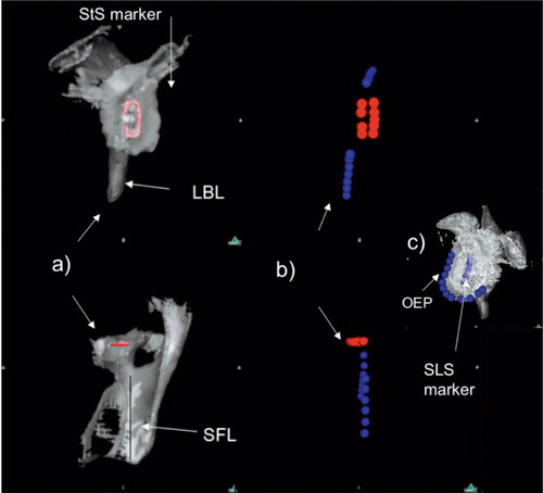
To establish the preoperative orientation of the glenoid, another set of points were positioned on the rim of the glenoid on the scapular images constructed from the preoperative CT scans. Finally, to establish the orientation of the implant, reference points were positioned on the metallic marker on reconstructions from the postoperative CT scans (). The marker was staple-shaped in the Neer II prostheses and a straight line in the Ulys Ceraver prostheses (). For both prostheses, the marker was oriented along the long axis (infero-superior) of the implant making it straightforward to evaluate inclination and rotation. Because the marker was a straight line for the Ulys Ceraver prosthesis, points were also digitized along the rim of the subchondral bone of the glenoid for the analysis of version ().
The 3 sets of reference points representing the blade of the scapula, the preoperative glenoid, and the implant were imported into 3D-Reshaper software (Technodigit, Gleizé, France). The set of points representing the blade of the scapula consisted of 2 subsets corresponding to the lines of the lateral border and supraspinous fossa, respectively. Based on these sets of points, the software calculated the best fit planes for the blade of the scapula, the preoperative glenoid, and the implant as well as the centers of the preoperative glenoid and the implant. This software also calculated the angles between the planes (or lines) and the distance (offset) from the centers of the glenoid and implant to the scapular plane ().
Figure 2. Glenoid and scapula reference points imported into 3D- Reshaper software. Glenoid-related descriptors are marked in red and scapula blade descriptors are marked in blue. On the left is shown the postoperative glenoid implant staple shape marker relative to the scapula plane (SbP). On the right is shown the preoperative eroded glenoid outer edge relative to the scapula plane. GP: glenoid plane; AG: glenoid supero-inferior axis; CG: central point of the glenoid; pCG: orthogonal projection of the central point of the glenoid on the scapula blade plane; Psj: intersecting line between scapula blade plane and glenoid plane.
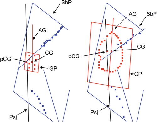
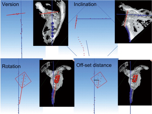
4 parameters of the preoperative glenoid position and of the glenoid implant position were investigated: version, inclination, rotation, and the anterior-posterior offset distance of the glenoid relative to the plane of the scapula (). The 3D-Reshaper software calculated the version as the angle between the plane of the glenoid (the preoperative glenoid as well as the glenoid implant) and the plane of the scapula. The inclination was calculated as the angle between the line that intersects the scapula blade plane and the glenoid plane and a line normal to the supraspinous fossa line. Rotation was calculated as the angle between the supero-inferior axis of the implant and the plane of the scapula. The offset distance was calculated as the shortest distance between the center of the arthritic glenoid or glenoid metallic marker and the plane of the scapula.
Figure 3. The four position parameters (version, inclination, rotation, and antero-posterior offset distance) are illustrated graphically. Calculated glenoid orientation is shown in red and scapula blade orientation is shown in blue.
Walch et al. (Citation1998) classified the extent of bone erosion, dividing the morphology of the glenoid bone into minor erosions (types A1 and B1), major erosions (types A2 and B2), and retroversion of more than 25° of dysplastic origin (type C). The labels “A” and “B” refer to the erosion being central or posterior, respectively.
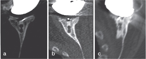
To assess perforation of the glenoid vault by the implant, the position of the keel of the implant relative to the outer cortex of the glenoid was categorized into 3 groups as assessed from postoperative CT scans (): implant centrally positioned with no contact between keel and cortex, contact between implant keel and cortex (anterior or posterior), and perforation of the cortex with cement leakage (anterior or posterior).
Figure 4. Axial CT views passing through the middle of the glenoid of 3 implants. On the left is shown the implant keel centrally positioned into the glenoid vault (a). In the middle is shown contact between the glenoid keel and the anterior glenoid wall (b). On the right is shown the glenoid keel perforating the anterior glenoid wall (c).
The indication for total shoulder replacement was destruction of the joint surface with pain and functional limitations that were unresponsive to conservative treatment. The mean (SD and range) patient age at the time of surgery was 70 (10) (48–84) years and the majority (25) were women. TSA was performed for primary osteoarthritis (23 cases), rheumatoid arthritis (1 case), posttraumatic arthritis (3 cases), and for arthritis related to previous surgery for instability (2 cases). Anatomical-type prostheses with keeled all-polyethelene glenoid components were used in all shoulders: a Neer II prosthesis (Smith and Nephew, Memphis, TN) was used in 20 shoulders and a Ulys prosthesis (Ceraver, Paris, France) was used in 9. In all cases, the glenoid component was sized with a guide template and fixed to the glenoid bone using cement.
The operative technique has been described previously (Franklin et al. Citation1988, Torchia et al. Citation1997, Mole et al. Citation1999). As the patient-specific native orientation was unknown, an arbitrary goal of glenoid position was to place the glenoid perpendicular to the plane of the scapula. Thus, correction of glenoid version towards neutral was guided by the version angle determined from the preoperative CT scan. Efforts to correct inclination towards neutral were based on the intraoperative appearance of the glenoid surface. Rotation and centering of the glenoid implant were adjusted according to the superior-inferior axis and the center of the arthritic glenoid.
Neutral placement of the glenoid component was attempted without specialized tool guides or navigational aids. Asymmetrical reaming was used to correct orientation due to erosion in order to get a glenoid rim perpendicular to the scapula plane. To achieve neutral version, a method widely used in clinical practice and described by Matsen et al. (Citation1994 was used in conjunction with the version angle determined from the preoperative CT scans: the surgeon’s finger was placed over the anterior glenoid rim, and the reamer was orientated towards an area where the anterior glenoid wall meets the body of the scapula. Thus, the implant was aligned along the glenoid vault axis direction but it was assumed that this axis ran parallel to the scapula blade and would ensure neutral version.
Statistics
The 4 preoperative positioning parameters of the eroded glenoid (version, inclination, rotation, and offset distance) were analyzed in relation to the respective postoperative parameters (version, inclination, rotation, and offset distance), with the use of the least-squares method. The preoperative version and the correction of version were analyzed in relation to the level of glenoid erosion according to the Walch classification with the use of analysis of variance. Significance was set at p < 0.05. Statistical analysis was performed using SPSS software version 10.0.
Results
Preoperative bone erosion vs. postoperative positioning
Preoperative retroversion of the eroded glenoid and postoperative retroversion of the implant () were determined. The correlation between these measurements was statistically significant. The average correction achieved appeared minor and the implant was inserted in a retroverted position reflecting that of the eroded glenoid ().
Figure 5. Preoperative axial view of the posteriorly eroded glenoid (left) and postoperative axial view of the same specimen with an implant (right). The orientation of the glenoid vault is indicated by the dotted line. The orientation of the eroded glenoid is indicated by the black line on the left part of the figure. The orientation of the glenoid implant is indicated by the white line on the right part part of the figure. The white arrow indicates anterior perforation of the glenoid vault due to the retroverted orientation of the implant in this preoperatively eroded glenoid.
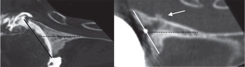
Table 1. Preoperative, postoperative, and correction values for each of the 4 positioning parameters (mean (SD) [range]). Correction was defined as postoperative version subtracted from preoperative version. Retroversion was defined as positive and anteversion negative; superior inclination was positive and inferior inclination negative; clockwise rotation was positive for a right shoulder and anticlockwise rotation was positive for a left shoulder; offset distance was always anterior to the scapular plane
For the other postoperative positioning parameters—inclination, rotation, and offset distance—the postoperative implant position was statistically correlated to the preoperative morphology of the eroded glenoid and little correction towards neutral positioning was achieved ().
Preoperative erosions were classified as minor in 16 cases (6 cases of type A1 and 10 cases of type B1), major erosions in 11 cases (7 cases of type A2 and 4 cases of type B2), and retroversion in excess of 25° in 2 cases (type C). The preoperative version correlated with the classification of erosion (p < 0.001) (). Defining the postoperative version as excellent if less than 5º from the neutral position, as satisfactory if between 5º and 10º from neutral, and as unsatisfactory if more than 10º from neutral, the postoperative version was found to be excellent for group A2, satisfactory for A1 and B1, and unsatisfactory for the most severely retroverted groups (B2 and C). Only groups B1 and C appeared to show postoperative version closer to neutral than preoperative version (correction); however, there was no significant correlation between correction and the level of preoperative erosion. Thus, a corrective effect of the procedure was not established.
Table 2. Preoperative version of the eroded glenoids (mean (SD)), postoperative version of the glenoid implants, and correction categorized according to preoperative erosion types using the classification system of Walch et al. (Citation1999). Change of version was defined as postoperative version subtracted from preoperative version
Implant position and perforation of the glenoid vault
The cortex of the glenoid vault was broken in 5 of the 29 cases, causing cement leakage ( and ). 4 of these involved the anterior cortex; perforation was due to excessive retroversion of the implant and 1 involved perforation of the posterior cortex due to excessive rotational malposition.
Table 3. Degree of implant perforation of the glenoid vault related to postoperative implant position (mean (SD)). “n” is the number of cases. The contact between the keel and cortex in row 3 did not cause perforation of the anterior cortex
When erosion of the glenoid was limited (grades A1 and B1), the keel was positioned at the center of the glenoid vault in 7 out of 16 cases, and only in 1 case was the cortex perforated (). In contrast, when erosion was excessive (grades A2, B2, or C), the keel of the implant was never centrally seated and in 4 cases the cortices were perforated. These data suggest a relationship between erosion and vault perforation. However, the number of cases with a perforated vault was not sufficient for a meaningful statistical analysis.
Table 4. Preoperative erosion as defined by Walch et al. (Citation1998) related to degree of implant perforation of the glenoid vault. The contact between the keel and cortex in column 4 did not cause perforation of the anterior cortex
Discussion
We found that the postoperative orientation of the glenoid component of TSA was determined by the preoperative glenoid morphology, and that statistically insignificant correction of the orientation was achieved. Prior to this study, Kircher et al. (Citation2009) and Iannotti et al. (Citation2012) reported on the relationship between the preoperative version of the glenoid and the postoperative implant version. Kircher et al. found that without navigational aids the preoperative retroversion was corrected from 14° (SD 6.1°) to 11° (7°), which is similar to what we found in this study (10° (10°) and 7° (11°), respectively). Iannotti et al. concluded that traditional methods to correct severe glenoid deformity are not consistent. They also found that if the deformity was minor (less than 10° of retroversion), the implant position was excellent in 4 of 6 cases and satisfactory in 2 of 6 cases. However, it was not clear whether the procedure had “corrected” the minor preoperative deformity. These findings are consistent with ours ().
The findings of Kircher et al. (Citation2009) and Iannotti et al. (Citation2012) were based on 10 and 13 cases, respectively, and our study involving 29 patients provides additional confidence in these results. Furthermore, our study shows that not only retroversion but also postoperative inclination, rotation, and offset are influenced by the preoperative glenoid morphology. To avoid metal artifacts during CT image reconstructions, Iannotti et al. estimated the implant orientation using an indirect method measuring a replica of the glenoid. In contrast, we measured the orientation of the actual glenoid component using a CT protocol that eliminates metal artifacts.
The other key finding of the present study is that excessive erosion of the glenoid was associated with poor seating of the implant within the glenoid vault. In all severely eroded glenoids, the implant was either in close contact (9 cases) or perforated the cortex of the glenoid vault (4 cases). Furthermore, this is likely to be a frequently occurring issue, because excessive erosion was found in 13 of 29 shoulders. The perforation was predominantly of the anterior cortex and associated with retroversion of the implant () as well as with both central and posterior preoperative erosion (). The 1 case of posterior perforation indicated that implant rotation may also play a role in vault perforation.
The high rate of cortical perforation in our study was similar to the findings of Yian et al. (Citation2005) who reported vault perforation in 10 of 47 patients. Surprisingly, and in contrast to the present study, Yian et al. found exclusively posterior perforation, but they did not attempt to relate cortical perforation and implant positioning to the level of glenoid erosion. The high rate of severe posterior erosions (6 of 29) in our study matches the findings of Walch et al. (Citation1999) and Iannotti et al. (Citation2003) who each reported severe posterior erosion in a quarter of their cases. Interestingly, Iannotti et al. did not find that severe erosion had any effect on postoperative ASES outcome scores following TSA. However, their study did not investigate how erosion had affected radiographic or clinical loosening. In a later study, Iannotti et al. (Citation2012) concluded that if preoperative glenoid retroversion is greater than 20°, it is difficult to place the glenoid component in neutral position by asymmetric reaming without perforating the glenoid vault. Hoenecke et al. (Citation2008) established a relationship between cortical perforation and the amount of implant version: implant retroversion in excess of 20° or anteversion in excess of 5° resulted in vault penetration. These findings by Iannotti et al. (Citation2012) and Hoenecke et al. are consistent with the results of the present study—of 20° and 2°, respectively (). In contrast to our in vivo study that measured the orientations and occurrence of perforations in real arthroplasties, the study by Hoenecke et al. was a purely computational one in which implants were virtually implanted into 3-D reconstructions of 40 scapulae. As mentioned earlier, Iannotti et al. estimated implant orientation using an indirect method, while in the present study a direct method was used. Also, Iannotti et al. investigated glenoid vault perforation of a pegged implant, Hoenecke et al. studied both a keeled and a pegged design, while the implants in the present study were both keeled. The consistency of results across these different methodologies and factors is reassuring.
One main criticism of our study is that the same 2 surgeons carried out all 29 shoulder arthroplasties. It can be argued that the orientation of the implant achieved and correction of the orientation from the preoperative morphology only represent the surgical techniques of these 2 surgeons. However, both surgeons were very experienced and used a well-established technique; thus, we believe that the orientation reported here is typical of what is achieved in surgical practice. Other limitations of the present study are the relatively low number of patients, which did not allow any of the findings regarding vault perforation to be determined with statistical significance, and also confounding factors such as the use of 2 different implants and different etiologies leading to TSA. However, the majority of procedures (23 of 29) were carried out for primary osteoarthritis and we suggest that the findings were not unduly influenced by these confounding factors.
The method for calculating version that we used differs from the standard method used in the other studies mentioned above. The standard protocol calculates the glenoid version from plain axial radiographs or using 2-D computed tomography scans in axial orientation (Friedman et al. Citation1992). The shortcoming of the standard technique is that it uses the midpoint of the glenoid surface to establish the neutral orientation. As the glenoid surface is often eroded, the neutral line defined in this way is affected by the pathology. It is questionable whether one should correct the orientation of an eroded glenoid towards a neutral line that is itself influenced by the erosion. The technique we used only used landmarks independent of the pathology to establish the orientation of the scapula (Amadi et al. Citation2008). Also, the technique used here, in addition to version, allowed the measurement of inclination, rotation, and antero-posterior offset distance. In any case, the reported mean preoperative retroversion of 14° (Habermeyer et al. Citation2006) and 16° (Walch et al. Citation1999) using the standard method is not inconsistent with the 10° found here.
In this study, we have indirectly—as is standard—treated the neutral orientation as the optimal and target orientation of the implant. However, the glenoid probably has a patient-specific orientation relative to the scapula, and the notion of one standard target of neutral orientation is possibly too simplistic. An alternative definition of optimal positioning, also likely to be patient-specific, is that of the implant keel being centrally fixed within the glenoid vault as shown on the left part of . However, much more extensive studies will be needed to understand patient-specific variation of the gleno-scapular relationship and the effect that this has on the optimal orientation of implant positioning. Establishment of patient-specific orientations will be further complicated in cases of eroded glenoids, and methods such as those suggested by CitationGanapathis et al. (2011) and Scalise et al. (Citation2008) for predicting the patient-specific glenoid orientation from pathological glenoids will be needed.
Another issue regarding treating the neutral orientation as the optimal (target) orientation is that in cases of severe erosion, asymmetrical reaming towards neutral may lead to removal of too much bone stock. The surgeon may therefore compromise and accept less than neutral orientation. Alternatively, the surgeon may try to build up the eroded part of the glenoid using bone grafting. Thus, when reconstructing a severely deformed glenoid, it may be incorrect to consider a non-neutral implant position to be a failing of the surgeon per se. However, it does highlight a difficult problem in TSA and that the procedure needs to be developed to reach the neutral position. We therefore considered implant orientations that are not neutral to be a measure of the inability of TSA to correct glenoid orientation.
It is beyond the scope of this paper to establish whether malalignment or glenoid vault perforation lead to poor clinical outcome, or what degree of correction is needed to achieve good clinical results. However, these links have been suggested in several other studies (Hennigan and Iannotti Citation2001, Hasan et al. Citation2002, Iannotti et al. Citation2005, Spencer et al. Citation2005), and it is probably reasonable to assume that perforation of the vault will complicate any revision procedures and should be avoided
In summary, we found that the implant position was determined by the preoperative orientation of the glenoid and that surgery does not achieve satisfactory orientation in moderate to severely eroded cases. Also, erosion of the glenoid was associated with perforation of the glenoid vault by the implant. If component malalignment or glenoid vault perforation are causes of poor clinical outcome, our study indicates that TSA would benefit from aids to allow proper seating of the implant on the glenoid rim and optimal fixation within the vault—while maintaining bone stock using bone grafting, augmented glenoids, or other methods.
TG carried out many of the surgeries and took part in the CT scanning, designed the study, and was integral to all aspects of the work. UH, AA, and RE were integral to the planning and design of the study, and review and interpretation of the results. CM and FT carried out the CT scans and took part in the interpretation of scans and characterization of erosion. BA carried out most of the surgeries and took part in the characterization of erosion and implant orientation as well as assessing the clinical significance of the findings. All authors took part in the writing of the manuscript.
The Arthritis Research Campaign (ARC) supported parts of this project.
No competing interests declared.
- Amadi HOHansen UN Wallace AL Bull AM. A scapular coordinate frame for clinical and kinematic analyses. J Biomech 2008; 41 (10): 2144-9.
- Bohsali KI, Wirth MA, Rockwood C A Jr. Complications of total shoulder arthroplasty. J Bone Joint Surg (Am) 2006; 88 (10): 2279-92.
- Churchill RS, Brems JJ, Kotschi H. Glenoid size, inclination, and version: Anatomical study. J Shoulder Elbow Surg 2001; 10 (4): 327-32.
- Codsi MJ, Bennetts C, Gordiev K, Boeck DM, Known YW, Brems JJ. Normal glenoid vault anatomy and validation of a novel glenoid implant shape. J Shoulder Elbow Surg 2008; 17 (3): 471-8.
- Farron A, Terrier A, Buchler P. Risks of loosening of a prosthetic glenoid implanted in retroversion. J Shoulder Elbow Surg 2006; 15 (4): 521-6.
- Franklin JL, Barrett WP, Jackins SE, Matsen FA, 3rd. Glenoid loosening in total shoulder arthroplasty. Association with rotator cuff deficiency. J Arthroplasty 1988; 3 (1): 39-46.
- Friedman RJ, Hawthorne KB, Genez BM. The use of computerized tomography in the measurement of glenoid version. J Bone Joint Surg (Am) 1992; 74 (7): 1032-7.
- Ganapathi A, McCarron JA, Chen X, Iannotti JP. Predicting normal glenoid version from the pathological scapula: a comparison of 4 methods in 2- and 3-dimensional models. J Shoulder Elbow Surg 2011; 20: 234-44.
- Gregory T, Hansen U, Emery RJ, Augereau B, Amis AA. Developments in shoulder arthroplasty. Proc Inst Mech Eng H 2007; 221 (1): 87-96.
- Habermeyer P, Magosch P, Luz V, Lichtenberg S. Three-dimensional glenoid deformity in patients with osteoarthritis: a radiographic analysis. J Bone Joint Surg (Am) 2006; 88 (6): 1301-7.
- Hasan SS, Leith JM, Campbell B, Kapil R, Smith KL, Matsen FA.Characteristics of unsatisfactory shoulder arthroplasties. J Shoulder Elbow Surg 2002; 11: 431-41.
- Hennigan SP, Iannotti JP. Instability after prosthetic arthroplasty of the shoulder. Orthop Clin North Am 2001; 32: 649-59.
- Hoenecke H R Jr,Hermida JC, Dembitsky N,Patil S,D’Lima DD. Optimizing glenoid component position using three-dimensional computed tomography reconstruction. J Shoulder Elbow Surg 2008; 17 (4): 637-41.
- Hopkins AR, Hansen UN, Amis AA, Knight L, Taylor M, Levy O, Copeland SA. Wear in the prosthetic shoulder: association with design parameters. J Biomech Eng 2007; 129 (2): 223-30.
- Iannotti JP, Norris TR. Influence of preoperative factors on outcome of shoulder arthroplasty for glenohumeral osteoarthritis. J Bone Joint Surg (Am) 2003; 85 (2): 251-8.
- Iannotti JP, Spencer EE, Winter U, Deffenbaugh D, Williams GR. Prosthetic positioning in total shoulder arthroplasty. J Shoulder Elbow Surg 2005; 14: 111S-21.
- Iannotti JP, Greeson C, Downing D, Sabesan V, Bryan JA. Effect of glenoid deformity on glenoid component placement in primary shoulder arthroplasty. J Shoulder Elbow Surg 2012; 21: 48-55.
- Kircher J, Wiedemann M, Magosch P, Lichtenberg S, Habermeyer P. Improved accuracy of glenoid positioning in total shoulder arthroplasty with intraoperative navigation: a prospective-randomized clinical study. J Shoulder Elbow Surg 2009; 18 (4): 515-20.
- Kwon YW, Powell KAYum JK,Brems JJ,Iannotti JP., Use of three-dimensional computed tomography for the analysis of the glenoid anatomy. J Shoulder Elbow Surg 2005; 14 (1): 85-90.
- Matsen FA, Lippitt SB, Sidles JA, Harryman DT. Practical evaluation and management of the shoulder. W.B. Saunders, Philadelphia 1994; 192-210.
- Mole D RO, Riand N, Levigne C, Walch G. Cemented glenoid components: results in osteoarthritis and rheumatoid arthritis. In: Shoulder arthroplasty (Eds Walch G and Boileau P). Springer, Berlin 1999: 163-71.
- Nguyen D, Ferreira LM, Brownhill JR, King GJ, Drosdowech DS, Faber KJ, Johnson JA. Improved accuracy of computer assisted glenoid implantation in total shoulder arthroplasty: an in-vitro randomized controlled trial. J Shoulder Elbow Surg 2009; 18 (6): 907-14.
- Nyffeler RW, Jost B, Pfirrmann CW, Gerber C. Measurement of glenoid version: conventional radiographs versus computed tomography scans. J Shoulder Elbow Surg 2003; 12 (5): 493-6.
- Rosset A, Spadola L, Ratib O. OsiriX: an open-source software for navigating in multidimensional DICOM images. J Digit Imaging 2004; 17(3): 205-16.
- Rosset C, Rosset A and Ratib O. General consumer communication tools for improved image management and communication in medicine. J Digit Imaging 2005; 18 (4): 270-9.
- Scalise JJ, Bryan J, Polster J, Brems JJ, Iannotti JP. Quantitative analysis of glenoid bone loss in osteoarthritis using three-dimensional computed tomography scans. J Shoulder Elbow Surg 2008; 17 (2): 328-35.
- Shapiro TA, McGarry MH, Gupta R, Lee YS, Lee TQ. Biomechanical effects of glenoid retroversion in total shoulder arthroplasty. J Shoulder Elbow Surg (3 Suppl) 2007; 16: S90-5.
- Spencer EE, Kambic H, Valdit A, Iannotti JP. The effect of humeral component anteversion on shoulder stability with glenoid component retroversion. J Bone Joint Surg (Am) 2005; 87: 808-14.
- Torchia ME, Cofield RH, Settergren CR. Total shoulder arthroplasty with the Neer prosthesis: long-term results. J Shoulder Elbow Surg 1997; 6 (6): 495-505.
- Walch G, Boulahia A, Boileau P, Kempf JF. Primary glenohumeral osteoarthritis: clinical and radiographic classification. The Aequalis Group. Acta Orthop Belg (Suppl 2) 1998, 64: 46-52.
- Walch G, Badet R, Boulahia A and Khoury A. Morphologic study of the glenoid in primary glenohumeral osteoarthritis. J Arthroplasty 1999; 14 (6): 756-60.
- Yian EH, Werner CM, Nyffeler RW, Pfirrmann CW, Ramappa A, Sukthankar A, Gerber C. Radiographic and computed tomography analysis of cemented pegged polyethylene glenoid components in total shoulder replacement. J Bone Joint Surg (Am) 2005; 87 (9): 1928-36.