
The patient is a woman born in 1960. She suffered a high transfemoral amputation due to a tumor in 1976. In 1993, she was enrolled for treatment with a custom-designed bone-anchored implant solution. The surgery was performed in 2 stages, Briefly, at stage 1 of surgery (S1), a titanium fixture was implanted in residual femoral bone after reaming of the intramedullary canal, and using a 3-D centering guide and fluoroscopy to ensure proper positioning. At stage 2 of surgery (S2) 6 months later, a full skin thickness flap was trimmed of subcutaneous fat and sutured to the distal end of the femoral bone, essentially according to the surgical technique developed for percutaneous bone-anchored hearing aids (Tjellstrom Citation1989). In conjunction with S2, a skin-penetrating abutment was inserted into the fixture and secured via an abutment screw. Following S2, the rehabilitation included a gradual increase of the load on the implant, the fitting of an external prosthesis to the abutment, increased activity, and prosthetic use. In 1998, the titanium fixture fractured at the distal end, and a custom-made abutment was installed to try to avoid fixture removal. This abutment failed in 2000, and was exchanged. In 2004, the fixture fractured again due to fatigue, and it was removed. The distal part was loose and was easily removed, while the proximal part was drilled out with a trephine burr together with a surrounding tissue collar. The fixture with surrounding bone was immersed in 4% formalin. The patient was successfully revised with a new implant and has not suffered from any new fracture.
Specimen preparation
The specimen was dehydrated and embedded in LR White (London Resin Co. Ltd., UK) and divided into 2 pieces through the long axis by use of a diamond band saw. One part was used for preparation of a toluidine blue stained ground section for histological and histomorphometrical analysis using light microscopy. The counter part of the block was divided further into one smaller part at the apical end, containing 7 threads intended for micro-CT analysis in a Skyscan 1172. The rest was polished with grit paper to create an even surface, and then sputter-coated with gold (approximately 10 nm) and analyzed by scanning electron microscopy (SEM).
Results
A large amount of bone tissue was found around the implant. One side was damaged by the trephine burring, and the hollow inside was damaged distally during removal (). The bone surrounding the implant was mainly mature cortical bone filling the threads and growing into the transversal holes to the center of the implant. The hollow proximal part of the implant was dominated by trabecular bone, which had a condensed appearance on the implant surface and in parallel alignment with the implant surface, while becoming more randomly distributed towards the center. The thread closest to the implant fracture lacked tissue and was not included in the histomorphometric measurements. The degrees of bone-implant contact and bone area within the 29 threads measured were 81% and 87%, respectively. The SEM analysis confirmed the large amount of bone surrounding and in contact with the implant, while no fibrous tissue was seen in the interface. Mature, remodeled bone with well-defined Haversian systems with surrounding osteocyte lacunae was frequently observed in the threads. Trabecular bone was observed, following the contours of the implant surface and extending into the hollow center at the distal part of the larger thread with the transversal hole. Differences in contrast in the bone tissue indicated active bone remodeling in the porous part of the bone, where areas of jagged bone surfaces indicated resorption by osteoclasts. Less mineralized bone had been laid at areas close to these zones, indicating coupled bone remodeling. Osteocyte lacunae were frequently observed close to the implant surface, usually at a distance of 10–20 µm (). Furthermore, at even higher magnifications using SEM, canaliculi were frequently observed in the bone, both as strictly transversal cuts (circular) and as longitudinal cuts (worm-shaped) with a diameter typically in the range of 200–400 nm (). These extended close to (within 1 µm of) the surface of the bone closest to the implant surface. Micro-CT analysis confirmed the histological analyses, showing cortical bone on the outer, threaded surface; trabecular bone was predominant in the hollow center ().
Figure 1. The implant system obtained in 2003. A. Overview image. B. Closer view of the bone-anchored part, showing a large amount of bone surrounding the implant. C. Overview image of the ground section, showing the material fracture at the distal end (arrows), the large amount of mainly compact bone around the implant (arrowheads), and trabecular bone inside the implant (*). There is a central area devoid of tissue due to the retrieval procedure (#).
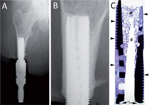
Figure 2. Light microscopic images of the ground section. A. Overview of one side of the implant. B. A closer view of one of the transversal holes in the implant, connecting the outer surface with the hollow inner part. C and D. Many threads were completely filled with mature, Haversian bone. E and F. Closer view of the bone in contact with the implant surface, with multiple osteocytes close to the implant surface. G. The trabecular bone in the hollow center with bone trabeculae reaching to and condensing at the implant surface.
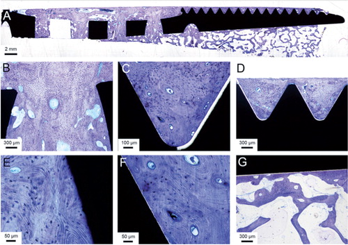
Figure 3. Back-scattered electron micrographs of the bone-implant bloc. A. Overview image of one side of the implant. B. A thread filled with compact bone, which contains several voids suggestive of vascular channels. C. Transversal hole with more porous bone, showing active remodeling with jagged areas (arrowheads) and newly, less mineralized osteoid (*). D. Haversian system (H) and osteocyte lacunae (oc), some of which are located close to the implant surface. E. At higher magnification close to the implant surface, showing canaliculi (c).
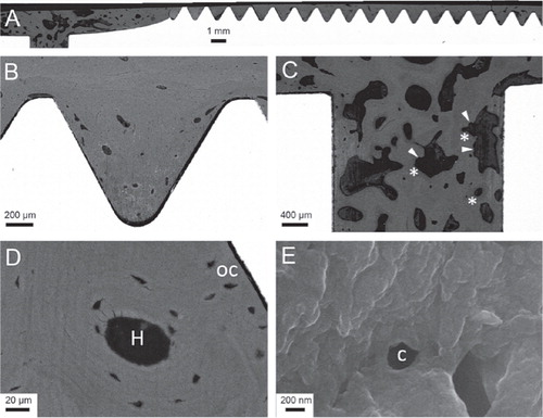
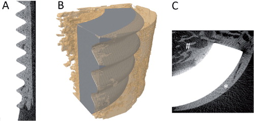
Figure 4. Micro-CT images. A. Longitudinal section of the data set with implant in white and bone in gray. B. Overlay image of contrast-segmented part of implant (gray) and bone (yellow; transparent) showing the osseointegration. C. Transaxial section of the data set with implant in white and bone in gray. The outer surface was dominated by cortical bone (*) and the inner surface was dominated by trabecular bone (#).
Discussion
In a prospective, single-center, non-randomized trial, we treated 51 consecutive patients with transfemoral amputation—mainly due to trauma or tumor—with an osseointegrated percutaneous prosthetic system. The cumulative success rate at 2-year follow-up was 92% (47 of 51 patients), including enhanced prosthetic use and mobility and improved quality of life (Branemark et al. Citation2014). The reasons for removal of the implant system were either deep infection (1 case), pain (1 case), or pain and loosening of the fixture (2 cases). Although there was a relatively short follow-up period (2 years), these results are encouraging considering previous attempts, which have failed to successfully attach amputation prostheses to the skeleton (Mooney et al. Citation1977, Hall Citation1985). Nevertheless, it is still important to determine the precise structural and functional connection between the bone and the fixture over time. The first prospective radiostereometric follow-up of osseointegrated amputation prostheses (Nebergall et al. Citation2012) showed similar limited early and low long-term migration and bone remodeling (e.g. an increased amount of bone around the proximal tip, so-called buttressing) as around long-term, successful uncemented hip stems.
An important objective in clinical studies on the structure of the fixture-bone interface is to obtain samples of such interfaces from patients. For obvious ethical reasons, biopsies of tissue in close contact with the intramedullar fixture cannot be obtained; they would most likely jeopardize the integrity of this interface. Furthermore, since animal experiments cannot reproduce the in vivo situation in humans after loading, it is important to retrieve and analyze samples that can be obtained if the fixture has been removed for reasons other than e.g. loosening and deep infection. In the present study, we analyzed unique material consisting of a retrieved implant with surrounding bone tissue from a patient treated during the early 1990s with a custom-designed titanium fixture for a bone-anchored transfemoral amputation prosthesis.
The histological evaluation showed that the bone tissue had grown in direct contact with the titanium implant, without any intervening fibrous tissue layer, creating an osseointegrated state (CitationDorland 2012). These results are in agreement with previously published data on oral and extra-oral maxiofacial implants with surrounding tissue retrieved from humans (Sennerby et al. Citation1991, Bolind et al. Citation2000). The direct comparison of implants retrieved from the oral and maxillofacial region with implants retrieved from femoral sites is not straightforward, but the concept of the latter has been developed from clinical experience and expertise obtained from the former (Robinson et al. Citation2004). For retrieved, uncemented metal arthroplasty, limited bone-implant contact has been reported (Cook et al. Citation1988, Lester et al. Citation1998). With the use of hydroxyapatite coatings, the bone-implant contact for hip arthroplasty could be increased by up to about 50% (Tonino et al. Citation1999). It has been shown previously that a large amount of bone can be seen around a bone-anchored amputation prosthesis retrieved from the upper extremity (ulnar bone) after 11 years of function, with 75% of bone area and 85% of bone-implant contact (Palmquist et al. Citation2008). The large amount of bone surrounding the present implant (87% of bone volume) when considering the threaded area, shows the potential of the screw design to effectively transfer the loads from the prosthesis to the skeleton. By histology, no areas of bone resorption due to stress shielding or excessive loads were observed.
An interesting observation is the difference in bone formed on the outer threaded surface and on the inner non-threaded surface, where there was a distinct difference in the type of bone that had formed. This is most likely due to the difference in loading, where less load is transferred at the center of the implant and higher loads are transferred to the surrounding cortical outer boundaries of the residual femur. No obvious differences were found along the tension or compressive surface of the bone in the transversal holes. It is believed that osteocytes are the mechano-sensing part of the bone tissue (Windahl et al. Citation2013). It has been discussed whether or not the canaliculi reach the implant surface (Steflik et al. Citation1992, Citation1994). In our case, we could show the presence of canaliculi close to (within 1 µm of) the implant surface. The separation between the bone and surface of machined implants is a commonly observed preparation artifact from the fixation and dehydration procedures (Lawton et al. Citation1995). Unfortunately, this hinders intact high-resolution analysis (Palmquist et al. Citation2009) and the actual bone-implant interface could not be visualized at higher magnifications, to allow a more detailed analysis and a better understanding of the canaliculi in this context.
Together with published studies on the quality of life for patients treated with osseointegrated amputation prosthesis (Hagberg et al. Citation2008), the present study indicates that osseointegration may be a promising long-term treatment option for patients with transfemoral amputation.
Sample preparation (BN), data acquisition (AP, BN), data analysis (AP, SW, RB, PT), writing the manuscript (AP, SW, RB, PT).
The study was supported by the Swedish Research Council (grant K2012-52X-09495-25-3), an LUA grant (ALFGBG-138721), BIOMATCELL VINN Excellence Center of Biomaterials and Cell Therapy (VINNOVA and Region Västra Götaland), the IngaBritt and Arne Lundberg Foundation, the Hjalmar Svensson Foundation, and the Dr Felix Neubergh Foundation, which are all gratefully acknowledged.
One of the authors (R.B.) is a shareholder in Integrum AB, a company developing osseointegrated implant system. The company had no influence on the content of the manuscript.
- Bolind P, Acton C, Albrektsson T, Bonding P, Granstrom G, Johansson C, . Histologic evaluation of retrieved craniofacial implants. Otolaryngol Head Neck Surg 2000; 123 (1 Pt 1): 140-6.
- Branemark R, Berlin O, Hagberg K, Bergh P, Gunterberg B, Rydevik B. A novel osseointegrated percutaneous prosthetic system for the treatment of patients with transfemoral amputation: A prospective study of 51 patients. Bone Joint J 2014; 96 (1): 106-13.
- Cook SD, Thomas KA, Haddad RJ, Jr. Histologic analysis of retrieved human porous-coated total joint components. Clin Orthop 1988; (234): 90-101.
- Dorland W AN. Dorland’s illustrated medical dictionary. 32. ed. Elsevier/Saunders: Philadelphia, Pa. 2012.
- Hagberg K, Branemark R, Gunterberg B, Rydevik B. Osseointegrated trans-femoral amputation prostheses: prospective results of general and condition-specific quality of life in 18 patients at 2-year follow-up. Prosthet Orthot Int 2008; 32 (1): 29-41.
- Hall CW. A future prosthetic limb device. J Rehabil Res Dev 1985; 22: 99-102
- Lawton DM, Oswald WB, McClure J. The biological reality of the interlacunar network in the embryonic, cartilaginous, skeleton: a thiazine dye/absolute ethanol/LR White resin protocol for visualizing the network with minimal tissue shrinkage. J Microsc 1995; 178 (Pt 1): 66-85.
- Lester DK, Campbell P, Ehya A, Rude RK. Assessment of press-fit hip femoral components retrieved at autopsy. Orthopedics 1998; 21 (1): 27-33.
- Mooney V, Schwartz SA, Roth AM, Gorniowsky MJ. Percutaneous implant devices. Ann Biomed Eng 1977; 5 (1): 34-46.
- Nebergall A, Bragdon C, Antonellis A, Karrholm J, Branemark R, Malchau H. Stable fixation of an osseointegated implant system for above-the-knee amputees: titel RSA and radiographic evaluation of migration and bone remodeling in 55 cases. Acta Orthop 2012; 83 (2): 121-8.
- Palmquist A, Jarmar T, Emanuelsson L, Branemark R, Engqvist H, Thomsen P. Forearm bone-anchored amputation prosthesis: a case study on the osseointegration. Acta Orthop 2008; 79 (1): 78-85.
- Palmquist A, Lindberg F, Emanuelsson L, Branemark R, Engqvist H, Thomsen P. Morphological studies on machined implants of commercially pure titanium and titanium alloy (Ti6Al4V) in the rabbit. J Biomed Mater Res B Appl Biomater 2009; 8; 91 (1): 309-19.
- Robinson K, Brånemark R, Ward D. Future developments: Osseointegration in transfemoral amputees. In: Atlas of amputations and limb deficiencies: surgical, prosthetic and rehabilitation principles ( Eds Smith D, Michael J, Bowker J). 2004: 673-81.
- Sennerby L, Ericson LE, Thomsen P, Lekholm U, Astrand P. Structure of the bone-titanium interface in retrieved clinical oral implants. Clin Oral Implants Res 1991; 2 (3): 103-11.
- Steflik DE, Hanes PJ, Sisk AL, Parr GR, Song MJ, Lake FT, . Transmission electron microscopic and high voltage electron microscopic observations of the bone and osteocyte activity adjacent to unloaded dental implants placed in dogs. J Periodontol 1992; 63 (5): 443-52.
- Steflik DE, Sisk AL, Parr GR, Lake FT, Hanes PJ, Berkery DJ, . Transmission electron and high-voltage electron microscopy of osteocyte cellular processes extending to the dental implant surface. J Biomed Mater Res 1994; 28 (9): 1095-107.
- Tjellstrom A. Osseointegrated systems and their application in the head and neck. Adv Otolaryngol Head Neck Surg 1989; 3: 39-70.
- Tonino AJ, Therin M, Doyle C. Hydroxyapatite-coated femoral stems. Histology and histomorphometry around five components retrieved at post mortem. J Bone Joint Surg (Br) 1999; 81 (1): 148-54.
- Windahl SH, Saxon L, Borjesson AE, Lagerquist MK, Frenkel B, Henning P, . Estrogen receptor-alpha is required for the osteogenic response to mechanical loading in a ligand-independent manner involving its activation function 1 but not 2. J Bone Miner Res 2013; 28 (2): 291-301.