
Abstract
Background and purpose — Intraoperatively, patient-specific positioning guides (PSPGs) represent the preoperatively planned alignment. We investigated the degree of correlation between preoperative planning and the alignment achieved postoperatively with the PSPG technique.
Patients and methods — TKAs performed with the PSPG technique between 2009 and 2011 were included. 39 patients (42 TKAs) volunteered for a postoperative CT scan. 2 independent observers performed the postoperative CT measurements. Preoperative component angles (target angles) in the coronal and axial planes were defined as 0 degrees, and in the sagittal plane on average 2.8 degrees for the femoral component and 3 degrees for the tibial component. A postoperative full-length standing anteroposterior radiograph was carried out in 41 TKAs.
Results — The femoral component was on average 1.2 (SD 1.5) degrees in varus, 4.4 (SD 4.0) degrees in flexion, and 0.5 (SD 1.4) degrees in external rotation. The tibial component was on average 0.4 (SD 2.5) degrees in varus and 3.7 (SD 2.3) degrees in flexion. A statistically significant difference between the target (preoperative software plan) and postoperative CT measurement was found for the femoral component angle in the frontal plane (p < 0.001; CI: 0.8–1.7), the sagittal plane (p = 0.01; CI –5.6 to –3.1), and the axial plane (p = 0.03; CI: 0.04–0.88). HKA angles were greater than 3 degrees from the neutral axis in 10 of the 41 cases.
Interpretation — We found our postoperative component alignment angles to be close to the software plan, especially for the tibial component. However, we found outliers in all planes and we cannot therefore conclude that the PSPG technique is a method that reproduces preoperatively planned alignment in a consistent manner.
Correct component positioning is important for long-term survival and clinical outcome in total knee arthroplasty (TKA) (CitationRitter et al. 1994, CitationBerger et al. 1998, CitationMatsuda et al. 2001). In the past decade, computer-assisted surgery (CAS) and—more recently—patient-specific positioning guides (PGPGs) have been developed to improve component positioning. Many authors have reported more outliers in the coronal plane when using the conventional technique for TKA, compared to intraoperative computer navigation ( CitationBathis et al. 2004, Ensini 2007, CitationRosenberger et al. 2008, CitationTingart et al. 2008). Other studies have not found any difference in outliers in the frontal plane between the 2 techniques (CitationKim et al. 2007, CitationYau et al. 2008). To date, attempts to improve component positioning with computer navigation have not led to improved femoral component rotation (CitationSiston et al. 2005, CitationMatziolis et al. 2007). A study from the Norwegian Arthroplasty Register found a higher short-term revision risk in TKA with computer assistance for the LCS Complete (Gothesen et al. 2011).
Patient-specific positioning guides (PSPGs) are based on either MRI data or CT data. Preoperatively, the knee component positions can be visualized in 3D-reconstructed images. Software allows planning of component positioning in all 6 degrees of freedom. According to the software plan, PSPGs are then manufactured. Intraoperatively, these PSPGs represent the component alignment determined from the preoperative software plan. A PSPG should fit snugly onto the patient’s unique anatomy and permit a TKA without the use of medullary instrumentation, as with the conventional operating technique, or without additional pin fixation, as with computer navigation. Some authors have reported better alignment in the frontal plane with use of PSPGs, compared to other techniques in TKA (CitationBoonen et al. 2012, CitationNg et al. 2012, CitationDaniilidis and Tibesku 2014, CitationMacdessi et al. 2014), while other studies have found no differences in alignment (CitationNunley et al. 2012, Chareancholvanich et al. 2013, CitationChotanaphuti et al. 2014, CitationWoolson et al. 2014). 1 study found better mechanical alignment with CAS than with patient-specific cutting guides (CitationNam et al. 2013), while another study found similar accuracy for PSPG and CAS (CitationMacdessi et al. 2014). To our knowledge, there have been no studies comparing the intended preoperative software plan with the postoperative alignment achieved. We therefore investigated the degree of correlation between the preoperative plan of component positioning and the position achieved postoperatively with the PSPG technique.
Patient and methods
We included the first TKAs (cemented Vanguard Complete Knee System; Biomet Inc., Warsaw, IN) performed with the PSPG technique (Signature Personalized Patient Care System; Biomet) between 2009 and 2011. 39 patients (18 females; 42 TKAs, 25 at Telemark Hospital, Skien, Norway and 17 at Oslo University Hospital) volunteered for a postoperative CT scan of the operated limb. Mean age at the time of surgery was 66 (44–86) years. A postoperative full-length standing anteroposterior radiograph was carried out in 41 TKAs.
All patients underwent a preoperative MRI according the Signature protocol. Dicom files from the MRI were uploaded and reconstructed by Materialise NV (Leuven, Belgium). The surgeon downloaded the reconstruction into the Signature software planner from Materialise NV. Suggested alignment and/or component sizes from the software upload were changed in cases where the surgeon disagreed with the proposed plan. After approval, the plan was uploaded again to Materialise and PSPGs were manufactured and shipped to the hospital.
Surgical technique
A midline skin incision followed by a medial parapatellar arthrotomy was performed. The femoral positioning guide was placed and fixed with pins distally and anteriorly. The distal pins were removed and the anterior pins were used for the direction of the distal femoral cut. After the distal cut, the 4-in-1 cutting block was placed by using the distal pinholes and cuts were performed. The tibial positioning guide was placed in a similar manner as the femoral guide. Then the tibial cut was performed. In all cases, a cruciate retaining knee implant was used. The tibial bearing had a built-in 3-degree posterior slope. A cruciate retaining total knee arthroplasty was cemented in place. Closure was done in layers. PSPGs fitted properly on both femur and tibia in all cases according to the surgeon’s description.
Postoperatively, a CT examination of the knee was performed using a protocol described by the Perth group for scanning and measurements (CitationChauhan et al. 2004). Multi-slice CT scanners (Philips Brilliance 2.6 and Siemens Emotion Somatom 6) were used for scanning. Measurements were performed with a standard workstation and software (Extended Brilliance Workspace).
The femoral mechanical axis in the frontal plane (the frontal femoral component angle, FFCA) was defined as the angle between a line from the center of the femoral head to the center of the femoral notch, and a line across the distal femoral component. The neutral mechanical axis was defined as 0°. Femoral alignment in the sagittal plane (the sagittal femoral component angle, SFCA) was defined as the angle between a line from the center of the femoral head to the deepest point of the notch, and a line parallel to the posterior flange of the femoral component.
Alignment in the femoral axial plane (the axial femoral component angle, AFCA) was defined as the angle between a line through the surgical epicondylar axis and a line parallel to the femoral posterior condyles. Tibial axis was defined in the frontal plane (the frontal tibial component angle, FTCA) as the angle between a line through the center of the tibial plateau and the center of the talus, and a line parallel to the tibial tray. The sagittal tibial component angle (STCA) is the angle between a line through the center of the tibial plateau and the ankle, and a line across the tibial base plate. shows preoperative plans and postoperative CT measurements for all the component angles described above.
Figure 1. Preoperative planning software (Materialise NV) and postoperative CT measurements for frontal femoral component angle (FFCA), sagittal femoral component angle (SFCA), axial femoral component angle (AFCA), frontal tibial component angle (FTCA), and sagittal tibial component angle (STCA).
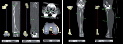
Measurements in the tibial axial plane were not performed, as tibial rotation was in most cases obtained by using an extramedullary guide from the Vanguard Total Knee system. In the frontal plane, measurements were conducted at the lateral side. 90° was subtracted, resulting in positive values for varus and negative values for valgus. In the sagittal plane, measurements were conducted posteriorly where positive values represented anterior slope (extension) and negative values posterior slope (flexion). In the axial plane, positive values indicated that the component was placed in external rotation, and negative values in internal rotation.
In the preoperative software plan, the FFCA and AFCA—and also FTCA—were proposed to be at 0°. As standard, the SFCA and STCA were proposed to be –3° (flexion) (). The surgeon was able to change these preoperatively proposed angles.
Before analysis, the protocol for CT measurements was evaluated by engineers from Biomet in order to assure that CT measurements were comparable to preoperative measurements obtained from MRI.
2 independent radiographers performed the CT measurements. Both radiographers underwent training before performing these measurements. The difference between the preoperative component plan and the alignment measured postoperatively was defined as the primary endpoint.
From the full-length standing anteroposterior radiograph, the hip-knee-ankle (HKA) angle was measured by using digital tools in IMPAX software v6.4.0.5024 (AGFA Healthcare NV). The HKA angle was defined by the angle between a line connecting the center of the hip and the center of the knee, and a line from the center of the knee to the center of the ankle. An HKA angle of 180° was considered to be neutral alignment. Angles greater and less than 180° represent valgus and varus, respectively.
Statistics
Quantitative data from the samples were expressed as mean (SD). Intraclass correlation (ICC) between the 2 observers was determined for all measured planes by using paired-samples correlation. A paired-samples t-test was conducted to express the difference in means between the 2 observers. The differences in means between preoperative plan (target) and postoperative CT measurements were analyzed using one-sample t-test in cases where the preoperative target was constant (FFCA, AFCA, FTCA, and STCA). As preoperative planning was not constant for the SFCA, a paired-samples t-test was used to analyze the difference in means between target and postoperative CT measurements for the SFCA. The level of significance was set at 0.05. The data were analyzed using IBM SPSS version 20.0.
Ethics
The Regional Committee for Medical and Health Research Ethics approved the study (REC West 2010/2056).
Results
Preoperative (target) angles in the planning software were changed in 5 cases to less flexion for the SFCA (–1.5°, –1.0°, and 3 times to –2.0°). For the other planes, the preoperatively proposed alignment angles were not changed (, first column).
Table 1. The target angle from the preoperatively planned alignment from planning software and postoperative CT measurements depicted as mean and SD from the 2 observers
Lowest intraclass correlation was 0.49 for the AFCA. All other angles showed good to excellent inter-observer reliability and significant agreement between the observers for all component angle measurements ().
Table 2. Intraclass correlation (ICC) between observer 1 and observer 2 in postoperative CT measurements
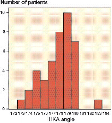
A statistically significant difference between preoperative plan (target) and postoperative CT measurement was found for FFCA (CI: 0.8–1.7), SFCA (CI: –5.6 to –3.1), and AFCA (CI: 0.04–0.88); no significant difference was found for the FTCA (CI: –0.3 to 1.2) and STCA (CI: –4.4 to –3.0) (). The box plot in shows the distribution in all planes for both the femur and the tibia. In the coronal, sagittal, and and axial planes respectively, the femoral component angle was on average 1.2° in varus (SD 1.5; planned 0°), 4.4° in flexion (SD 4.0; planned on average 2.8°), and 0.5° in external rotation (SD 1.4; planned 0°) (). For the tibial component angle in the coronal and sagittal planes, the component was on average 0.4° in varus (SD 2.5; planned 0°) and 3.7° posterior slope (SD 2.3; planned –3°) (). The graph in depicts the distribution of the postoperative HKA angles. In 40 of the 41 cases, the HKA angle was in neutral or in varus deviation. HKA angles were greater than 3° from the neutral axis in 10 cases; all these cases were aligned in varus. In 6 cases, the HKA angle and the FFCA and/or the FTCA aligned more than 3° from neutral axis.
Figure 2. Box plot showing the distributions of FFCA, SFCA, AFCA, FTCA, and STCA. The boxes show the median and interquartile range (IQR). The whiskers represent the range where the lowest and highest values are not more than 1.5 × IQR above the median. Circles represent outliers, i.e. values more than 1.5 × IQR from the median.
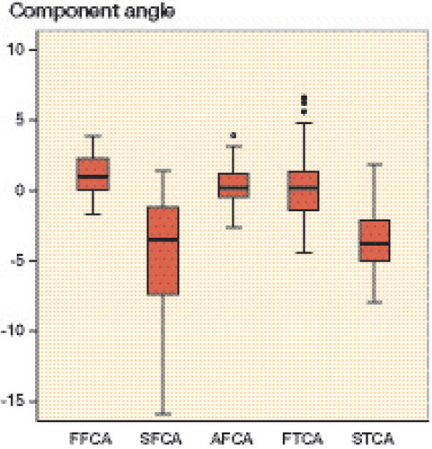
Figure 3. Distribution of the postoperative HKA angle. Angles greater and less than 180 degrees represent valgus and varus, respectively.
Discussion
In this study, we have examined postoperative alignment achieved with MRI-based software planning and the use of PSPGs. Our hypothesis was that our postoperative measurements would be close to the preoperatively planned values. We found statistically significant agreement between our preoperative software plan and postoperative CT measurements for the tibial component in the 2 measured planes, but not in all the planes for the femoral component. Although we did not find statistically significant agreement for the femoral component, our alignment results are within acceptable confidence intervals (95% CI for the FFCA: 0.8–1.7; 95% CI for the SFCA: –5.6 to –3.1; and 95% CI for the AFCA: 0.04–0.88).
We found outliers in all planes. Possible explanations are inaccuracies in the identification of landmarks from the preoperative MRI and from the postoperative CT. Other possible explanations are intraoperative errors such as fixation of cutting blocks, rigidity of the sawblade, and errors in intraoperative positioning of the PSPGs. Some of our patients were operated 3–6 months after the preoperative planning and production of the PSPGs. During this time, progression of osteoarthritis may have changed the anatomy enough to cause inferior fit of the PSPGs and worse alignment than originally planned. In cases with full cartilage defects, both surgeons experienced that there was occasionally a gap between the distal joint surface of the affected condyle and the PSPG. In other cases, it looked as if there was a snug fit of the PSPG with the joint surface. Distally, the PSPG was fixed with 2 spring-pins (one on each condyle). In cases where there was a gap between the distal condyle and the PSPG, the spring-pin forced the relatively flexible PSPG towards the condylar surface. This finally led to contact between the PSPG and the joint surface. By forcing the guide towards the condyle, the resulting position of the PSPG may have changed, and thereby changed the alignment. We assumed that this finding was due to the fact that the preoperative MRI protocol gave a good overview of cartilage, but a less accurate determination of the joint surface in cases in which there was sclerotic bone with full cartilage loss. This was confirmed by the company that manufactured our total knee system (Biomet Inc.). In cases with full cartilage loss and sclerotic bone in one of the femoral condyles, the endpoint of the bone could be difficult to identify. In order to ensure proper fit of the guide, a margin was built in by the manufacturer, which could have led to a small gap between the condylar surface with full cartilage loss and the PSPG. To avoid such a change in position of the PSPG, we should have accepted this gap intraoperatively in order to ensure that there would be no change in the position of the PSPG. The CT protocol had been discussed with the engineers from Biomet who were responsible for landmark identification in the preoperative MRI in order to identify the same joint centers and axis measurements in both protocols. The Signature protocol that we used was based on MRI, and our postoperative measurements were based on CT. Low intra- and inter-observer variability of landmark identification on a CT scan that defines the coordinate system of the femur and tibia has been reported (CitationVictor et al. 2009). Landmarks from the preoperative plan are gained from an MRI, and it is not certain that bony landmarks from MRI can be obtained with the same low intra-observer and inter-observer variability as for CT.
Average mechanical coronal femoral and tibial component angles were close to those in the preoperative plan. We found that the ranges for the femoral and tibial component axes were comparable to those in other alignment studies comparing the conventional operational method to CAS (CitationMatziolis et al. 2007, CitationRosenberger et al. 2008). One study (Chareancholvanich et al. 2013) found that all femoral and tibial component angles were within 3° of the mechanical axis with the PSPG technique, while we had outliers ranging from 1.7° valgus to 3.9° varus for the femoral component and from 4.4° valgus to 6.7° varus for the tibial component.
The sagittal femoral component position varied from over 15° in flexion to 1.5° in extension (target on average 2.8° of flexion), and this range varied more than results from other studies (CitationRosenberger et al. 2008, CitationChotanaphuti et al. 2014), although CitationTingart et al. (2008) reported a wider range. Some femoral components are placed far in excess of the planned average of 2.8° of flexion. The femoral component has a very tight fit when introducing it in place. This was different from the earlier implant used in both departments involved in the study (AGC; Biomet). The learning curve for using this implant, combined with too little rigidity of the saw blade, may explain some of the in-flexion positioned femoral components. For the tibial component, our preoperative target was 3° of posterior slope in all cases. Our measurements varied from 5.0° more slope to 4.8° less slope. These results are comparable to those in other studies (CitationMatziolis et al. 2007, CitationRosenberger et al. 2008).
The radiographers performed CT measurements before starting the measurements for this study, in order to rule out a learning curve. We found good to excellent ICC values for all planes, except for the femoral axial plane. Difficulties in identifying the correct epicondylar axis might explain this. We found some uncertainty with our measurements in the axial femoral plane. CitationSiston et al. (2005) compared 4 conventional navigation techniques and 1 computer-assisted navigation technique. They found that the rotation of the femoral component was within 5° of the reference transepicondylar axis in only 95 of 550 knees, with errors ranging from 13° of internal rotation to 16° of external rotation. Measurements in our study varied from 2.6° of internal rotation to 3.9° of external rotation. CitationMatziolis et al. (2007) found ranges that were more comparable to our results. Some studies have not found better rotational alignment with the PSPG technique than with the conventional method (CitationWoolson et al. 2014) and CAS (CitationMacdessi et al. 2014), while another study (CitationChotanaphuti et al. 2014) found better alignment with the PSPG technique. We found that one quarter of the HKA angles were more than 3° deviated from the neutral axis. This result appears to be comparable to the results of some studies using the conventional technique ( CitationBathis et al. 2004, CitationPerlick et al. 2004, CitationYau et al. 2008, CitationNg et al. 2012), using CAS (CitationKim et al. 2007, CitationYau et al. 2008), and using PSPGs (only 1 study) (CitationNam et al. 2013). However, several studies using CAS ( CitationBathis et al. 2004, CitationPerlick et al. 2004, CitationNam et al. 2013) and PSPGs (CitationNg et al. 2012, CitationDaniilidis and Tibesku 2014, CitationMacdessi et al. 2014) have reported fewer outliers. The preoperative MRI planning does not take into account soft tissue balancing, and some of the malalignments of the HKA angle might be explained by improper soft tissue balancing. We do not have an explanation for the fact that all outliers were in varus.
The first PSPGs did not have guidance for rotation of the tibial component. In our study, tibial rotation was obtained by using an extramedullary guide in most cases. In later PSPG design, the rotation of the tibial component was included in the preoperative planning. If the PSPG is used as a tool for determining the rotation of the tibial component, it is crucial to use the same component size, as planned preoperatively. In cases another tibial tray size had to be used intraoperatively, conventional instrumenation is mandatory. In 10 of 25 cases at Telemark Hospital, we disagreed intraoperatively with the planned size and we therefore implanted a larger or smaller tibial tray. In these cases, an extramedullary guide from the Vanguard Total Knee System was used to define tibial rotation. In support of our findings CitationStronach et al. (2013) reported that intraoperative tibial tray size was changed in half of 66 cases in which the PSPG technique was used. This study suggests that determination of tibial tray rotation is often dependent on conventional techniques.
We only described the alignment outcome of PSPG and did not compare this with other existing surgical techniques. Another limitation of this study was the fact that we included the first cases operated with the PSPG method, and the learning curve may have been a factor in causing variable results. We included TKAs performed by 2 surgeons at 2 hospitals to minimize bias in our results.
Most studies on this guidance technique have concentrated on postoperative coronal alignment. No studies have been published that have compared preoperative software planning with postoperative alignment. We found that our postoperative component alignment angles were close to those planned in the software, although not statistically significantly so for the femoral component angles. We also found outliers in all planes, so we cannot conclude that the PSPG technique is a method that reproduces preoperatively planned alignment in a consistent way.
JvL, SR, and BG designed the study and gathered the data. Statistical analysis was performed by JvL. All the authors were involved in data interpretation and in writing of the manuscript.
CT measurements were performed by Mona Risdal and Silje Klausen, both working as radiographers at the Center of Implant and Radiostereometric Research, Oslo. We thank Ragnhild Sørum Falk, researcher at the Department of Biostatistics and Epidemiology, Oslo University Hospital, for statistical support.
None of the authors received any financial funding or other support from companies for this study. One author (JvL) has received payments as a consultant for Biomet.
- Bathis H, Perlick L, Tingart M, Luring C, Zurakowski D, Grifka J. Alignment in total knee arthroplasty. A comparison of computer-assisted surgery with the conventional technique. J Bone Joint Surg Br 2004; 86 (5): 682-7.
- Berger RA, Crossett LS, Jacobs JJ, Rubash HE. Malrotation causing patellofemoral complications after total knee arthroplasty. Clin Orthop Relat Res 1998; (356): 144-53.
- Boonen B, Schotanus MG, Kort NP. Preliminary experience with the patient-specific templating total knee arthroplasty. Acta Orthop 2012; 83 (4): 387-93.
- Chareancholvanich K, Narkbunnam R, Pornrattanamaneewong C. A prospective randomised controlled study of patient-specific cutting guides compared with conventional instrumentation in total knee replacement. Bone Joint J 2013; 95-B (3): 354-9.
- Chauhan SK, Clark GW, Lloyd S, Scott RG, Breidahl W, Sikorski JM. Computer-assisted total knee replacement. A controlled cadaver study using a multi-parameter quantitative CT assessment of alignment (the Perth CT Protocol). J Bone Joint Surg Br 2004; 86 (6): 818-23.
- Chotanaphuti T, Wangwittayakul V, Khuangsirikul S, Foojareonyos T. The accuracy of component alignment in custom cutting blocks compared with conventional total knee arthroplasty instrumentation: prospective control trial. Knee 2014; 21 (1): 185-8.
- Daniilidis K, Tibesku CO. A comparison of conventional and patient-specific instruments in total knee arthroplasty. Int Orthop 2014; 38 (3): 503-8.
- Ensini A, Catani F, Leardini A, Romagnoli M, Giannini S. Alignments and clinical results in conventional and navigated total knee arthroplasty. Clin Orthop Relat Res 2007; 457: 156-62.
- Gothesen O, Espehaug B, Havelin L, Petursson G, Furnes O. Short-term outcome of 1,465 computer-navigated primary total knee replacements 2005-2008.Acta Orthop 2011; 82 (3): 293-300.
- Kim YH, Kim JS, Yoon SH. Alignment and orientation of the components in total knee replacement with and without navigation support: a prospective, randomised study. J Bone Joint Surg Br 2007; 89 (4): 471-6.
- Macdessi SJ, Jang B, Harris IA, Wheatley E, Bryant C, Chen DB. A comparison of alignment using patient specific guides, computer navigation and conventional instrumentation in total knee arthroplasty. Knee 2014; 21 (2): 406-9.
- Matsuda S, Miura H, Nagamine R, Urabe K, Hirata G, Iwamoto Y. Effect of femoral and tibial component position on patellar tracking following total knee arthroplasty: 10-year follow-up of Miller-Galante I knees. Am J Knee Surg 2001; 14 (3): 152-6.
- Matziolis G, Krocker D, Weiss U, Tohtz S, Perka C. A prospective, randomized study of computer-assisted and conventional total knee arthroplasty. Three-dimensional evaluation of implant alignment and rotation. J Bone Joint Surg Am 2007; 89 (2): 236-43.
- Nam D, Maher PA, Rebolledo BJ, Nawabi DH, McLawhorn AS, Pearle AD. Patient specific cutting guides versus an imageless, computer-assisted surgery system in total knee arthroplasty. Knee 2013; 20(4): 263-7.
- Ng VY, DeClaire JH, Berend KR, Gulick BC, Lombardi AVJr. Improved accuracy of alignment with patient-specific positioning guides compared with manual instrumentation in TKA. Clin Orthop Relat Res 2012; 470 (1): 99-107.
- Nunley RM, Ellison BS, Zhu J, Ruh EL, Howell SM, Barrack RL. Do patient-specific guides improve coronal alignment in total knee arthroplasty? Clin Orthop Relat Res 2012; 470 (3): 895-902.
- Perlick L, Bathis H, Tingart M, Perlick C, Grifka J. Navigation in total-knee arthroplasty: CT-based implantation compared with the conventional technique. Acta Orthop Scand 2004; 75 (4): 464-70.
- Ritter MA, Faris PM, Keating EM, Meding JB. Postoperative alignment of total knee replacement. Its effect on survival. Clin Orthop Relat Res 1994; (299): 153-6.
- Rosenberger RE, Hoser C, Quirbach S, Attal R, Hennerbichler A, Fink C. Improved accuracy of component alignment with the implementation of image-free navigation in total knee arthroplasty. Knee Surg Sports Traumatol Arthrosc 2008; 16 (3): 249-57.
- Siston RA, Patel JJ, Goodman SB, Delp SL, Giori NJ. The variability of femoral rotational alignment in total knee arthroplasty. J Bone Joint Surg Am 2005; 87 (10): 2276-80.
- Stronach BM, Pelt CE, Erickson J, Peters CL. Patient-specific total knee arthroplasty required frequent surgeon-directed changes. Clin Orthop Relat Res 2013; 471(1): 169-74.
- Tingart M, Luring C, Bathis H, Beckmann J, Grifka J, Perlick L. Computer-assisted total knee arthroplasty versus the conventional technique: how precise is navigation in clinical routine? Knee Surg Sports Traumatol Arthrosc 2008; 16 (1): 44-50.
- Victor J, Van Doninck D, Labey L, Innocenti B, Parizel PM, Bellemans J. How precise can bony landmarks be determined on a CT scan of the knee? Knee 2009; 16 (5): 358-65.
- Woolson ST, Harris AH, Wagner DW, Giori NJ. Component alignment during total knee arthroplasty with use of standard or custom instrumentation: a randomized clinical trial using computed tomography for postoperative alignment measurement. J Bone Joint Surg Am 2014; 96 (5): 366-72.
- Yau WP, Chiu KY, Zuo JL, Tang WM, Ng TP. Computer navigation did not improve alignment in a lower-volume total knee practice. Clin Orthop Relat Res 2008; 466 (4): 935-45.