
Abstract
We present a new result of pattern recognition generation scheme using a small-scale optical muscle sensing system, which consisted of an optical add-drop filter incorporating two nonlinear optical side ring resonators. When light from laser source enters into the system, the device is stimulated by an external physical parameter that introduces a change in the phase of light propagation within the sensing device, which can be formed by the interference fringe patterns. Results obtained have shown that the fringe patterns can be used to form the relationship between signal patterns and fringe pattern recognitions.
Introduction
In recent years, researchers have attempted to analyze and research in order to find the mechanism and instrumentation for the elderly and disabiled (CitationRodriguez et al. 2012, CitationRastogi et al. 2010, CitationKiran et al. 2013, CitationPrathyusha et al., 2013, CitationVelazquez et al. 2012, CitationPatel and Goud 2012, CitationBark et al. 2010), where most of them have built the system to assist or facilitate the ability. One of the approaches has been widely investigated and used in many areas of applications (CitationPicard et al. 2010, CitationPongpanitanont et al. 2010, CitationYoung et al. 2013, CitationZaja and Rojahn 2008, CitationFan et al. 2012, CitationKarg et al. 2010), which is the use of pattern recognition for computer interfacing applications. In this study, we propose the use of optical technique using the interference fringe patterns generated by a small-scale optical system. Apparently, the fringe pattern analysis is an extensively known technique and method in scientific and industrial applications, where mainly the purpose of fringe pattern analysis is the extraction of some physical quantities from the optical phase distribution, which is coded by one or several fringe patterns (CitationBernini et al. 2009). Meanwhile, the previously mentioned techniques and methods seemed to have been used in a wide range of applications (CitationAlam et al. 2010, CitationKamal 2008, CitationChioreanu et al. 2008, CitationKwon et al. 2010, CitationChen et al. 2012, CitationKim et al. 2010). Therefore, if we can take the principle of fringe pattern recognition and apply it in conjunction with the sensor, optical, and other devices, then it can be useful for many applications.
Nowadays, small-scale optical devices have been used to study the characteristics of light, which have led to the design and implementation in many works. These devices have also become the most widespread tools and their use has become the most common approach for many fundamental and applied researches. Moreover, optical devices and methods have drawn increasing attention due to their great potential in various applications, for instance, communication (CitationWinzer 2012), security (CitationSingh et al. 2012), and agriculture (CitationPullanagari et al. 2011), which were applied for the detection of signal and the particles within human body for medical applications (CitationSuwanpayak et al. 2011a, Citation2011b, CitationTamee et al. 2013). Conventionally, there are various methods of generating fringe patterns; for example, digital projectors and laser interference have been widely used to obtain fringe patterns (CitationLi and Zhang 2010). These techniques have been widely applied to numerous applications in optical metrology. In this paper, the optical device system is designed in order to obtain fringe pattern generation. In simulation, the fringe patterns can be formed by the change in optical path lengths that results in change in refractive index, which can be used to form the required fringe patterns. In principle, the received fringe patterns can be distinguished and they formed different input data for pattern recognition system through the interfacing sensors, where they are based on stimulations to the morphology of a dielectric waveguide due to the photoelastic effects (CitationAli et al. 2012), which are caused by the external environments due to the muscle movements. The advantage of optical sensors is the accuracy and precision on small-scale optical devices, which need high efficiency tools as well, where the integrated nonlinear optical PANDA-type ring resonator has shown their potential of use to meet such requirements (CitationSrinuanjan et al. 2012).
In this study, new results of optical muscle sensor for fringe pattern generation using the advantage of a nonlinear optical ring resonator known as a PANDA ring circuit are proposed, which consisted of a center ring resonator incorporating two smaller ring resonators on the right and left sides. This study is the extended results of the study by K. Tamee et al., with somemore results added, where the various fringe patterns are generated for patten recognition and computer interfacing and command applications. The device material used is InGaAsP/InP, which can also be coated by Au or other conducting materials, Ag, Cu etc., for wider applications. In principle, a change in phase of optical device within the PANDA ring circuit can be generated and related to the required applied parameters. Using the Opti-wave and MATLAB programs, the results obtained have shown that a variety of fringe patterns can be configured by the PANDA ring circuit, in which the obtained fringe patterns can be used to form a relationship between the signal patterns, that is, a number of fringes and fringe pattern recognitions, which is useful for computer language applications for the disabled.
Operating principle
In , the PANDA ring circuit is used for fringe pattern generation. The input waves (lights) can be in the forms of soliton or Gaussian pulses. In simulations, the input waves are fed into the system through different ports such as add and through ports. By using the practical device parameters, the simulation results are obtained using the Optic-wave program (OptiFDTD 2008).
Figure 1. Schematic diagram of a fringe pattern generator using PANDA ring resonator, where Es: optical fields, Ks: coupling coefficients, Rs: ring radii.
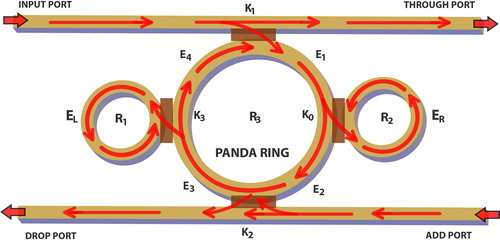
The schematic diagram of a fringe pattern generator using a PANDA ring circuit consists of three micro-ring resonators. For the PANDA ears, the output optical fields from the right and left rings are expressed as
ER and EL are the outputs from the right and left rings of PANDA ring circuit. Inside the system E1, E2, E3, and E4, are the output of the optical fields that are show in (3)–(6). Where k is the coupling coefficient, γ is the insertion loss, α is the attenuation loss, L is the optical path length, and kn is the propagation constant.
Therefore, the final equations for drop port and through port power are obtained and given by Eqs. (7)–(10).
Here, Pthrough and Pdrop represent the output power of the through part and drop port, respectively.
By the above equations, simulation results can be obtained using the MATLAB program; however, in this paper, the same parameters are used in the following section but the simulation program employed is the finite difference time domain (FDTD) method called Opti-wave, where the same output can be plotted.
Results and discussion
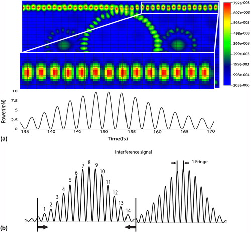
In this section, we described the use of the small-scale optical devices, which can be used to generate the required fringe patterns. The schematic diagram of a transducer using a PANDA ring resonator is shown in , the left (R1) and the right (R2) rings are placed as a reference ring. (a) shows the result of interference fringes within a PANDA ring waveguide InGaAsP/InP, where the used parameters of the radius R1 = R2 = 0.775 μm and R3 are varying from 1.365 to 1.765 μm, Aeff = 0.30 μm2, neff = 3.14, n2 = 1.3 × 10− 13 cm2/W; all coupling coefficients (κi) are 0.5, γ = 0.01, λ0 = 1.55 μm. In operation, the result of input Gaussian beams with center wavelength of 1.55 μm and power of 10 mW is introduced into the input port of the PANDA ring circuit. The required interference fringes can be detected and observed at the through port, which are the fringe patterns, which can be changed and different output can be generated by the external physical parameters, whereas in this case the muscle movements are the external enforcements. Thus, the measurement and filtering of the interference signals can be employed using the data analysis methods including fringe counting (CitationLu et al. 2013), phase tracking (CitationChang et al. 2009), fringe tracking (CitationMa and Bock 2005), and fringe analysis (CitationZhong et al. 2013, CitationWang et al. 2012) via the through port output signals. In this study, the fringe counting method is applied to distinguish the obtained interference fringes. A series of sensors can be installed and many forms of fringe patterns can be obtained by the very small devices in applications, which can be fabricated in the form of thin film using thin-film technology. Moreover, the advantage of a PANDA ring circuit is that the increase in fringe number can be easily obtained using the nonlinear effects produced by the two side rings, which is useful for high capacity applications. (b) shows the fringe generation and counting detail, where the total fringe number is 14.
Figure 2. Shows the simulation results, where (a) fringe pattern of through port generated by a PANDA ring circuit(R3 = 1.765 μm) and (b) fringe pattern counting method.
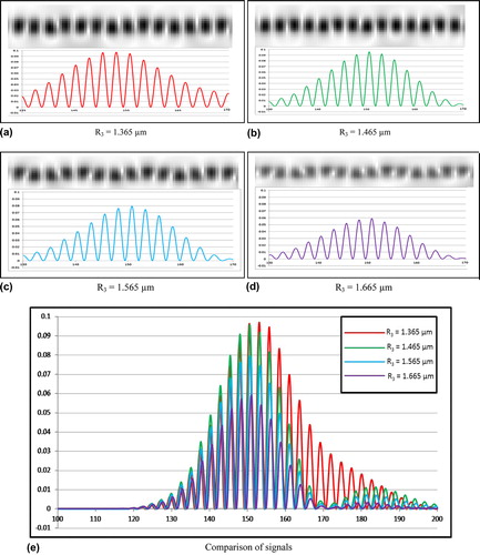
shows the simulation result of fringe pattern, where (a) R3 = 1.365 μm, (b) R3 = 1.465 μm, (c) R3 = 1.565 μm, (d) R3 = 1.665 μm, and (e) comparison of signals. The obtained data are at the center ring (R3), which varied from 1.365 to 1.665 μm. When change in optical path length of the ring (sensor) is occurred, the ring shape is distorted and the optical path length (L) is changed by ΔL and due to the strain-optic effects. The change in refractive index (n) is changed by Δn. The different fringe patterns and signals are obtained at the through port output. The resonant wavelength, λm, is shifted by Δλm, which is given by the formula [(Δλm/λm) = (Δn/n) + (ΔL/L)]. Here, m is the integer, n is the refractive index of the guiding material, and L is the circumference of the ring resonator. The different simulation results presented the capability of fringe pattern generation using the PANDA ring circuit. The results obtained have shown that when the optical path length is changed, the different fringe patterns (fringe number) are obtained. In this process, when the change in the center ring (R3) is 1.365, 1.465, 1.565, and 1.665, respectively, the obtained fringe patterns are clearly generated by PANDA ring circuit.
Figure 3. Shows the simulation results of fringe patterns generated by a PANDA ring circuit, where (a) R3 = 1.365 μm, (b) R3 = 1.465 μm, (c) R3 = 1.565 μm, (d) R3 = 1.665 μm, and (e) comparison of signals.
shows a schematic diagram of the proposed system, which consists of three main parts, including PANDA ring circuit, fringe pattern generated by PANDA ring circuit, and signal pattern recognition of fringe pattern. To form the fringe pattern, the Gaussian pulse (commercial laser source) is launched into the input port of PANDA ring circuit. The fringe pattern generated by PANDA ring circuit can be viewed by light intensity, and the interference signal is formed using the Opti-wave program. In addition, the obtained results are shown by the interference fringes, which can be directly counted or done using the fringe correlation analysis. In pattern recognition applications, the received signals are required to improve the signal and fringe pattern recognitions in order to obtain the appropriate patterns, which comprise the substeps including preprocessing that can be used to verify the integrity signal and feature extraction to obtain a qualified pattern according to the process of classification. Finally, the information from the signal can be used to form through the process earlier in order to apply in various fields.
Figure 4. Shows the schematic diagram of fringe pattern generation and interpretation using the proposed design system, where the ring radii varied from 1.365 to 1.665 μm.
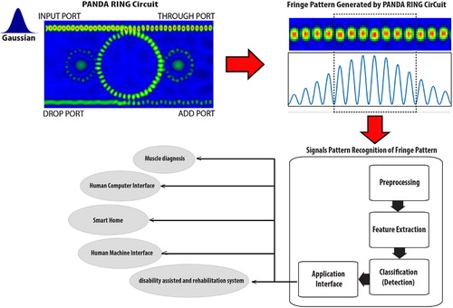
In terms of interfacing applications, the received signals can be used to control and command the computer, such as equipment or tools that can be used to assist people with disabilities by setting the different codes and commands; for instance, the use of wheelchair relies on the movements such as forward, backward, turn left, turn right, accelerate, stop, which requires six commands to control its movement. Finally, we can also use the pattern of different signals from different fringe patterns on multipurpose applications such as disability-assisted and rehabilitation system, smart home, human–computer interface and human–machine interface.
Conclusion
We have demonstrated the use of a small-scale optical system to generate the fringe patterns, which can be used to form the computer commands for disability applications. Such a system can be a tiny thin film device suitable for various applications. The device material used is InGaAsP/InP, which can also be coated by Au or other conducting materials, Ag, Cu etc., for wider applications. The principle is the same and was given by Tamee et al., but more details and different results are given for sensor and pattern recognition usage, which is useful for computer and machine interfacing applications. The change in the phase of optical devices can be configured to the optical path length variation within the PANDA ring resonator. Simulation results of the proposed system are derived from the change in optical path length of the resonant mode response, which is stimulated by the optical device parameters. The results obtained have shown that a variety of fringe patterns can be configured by the PANDA ring circuit. The obtained fringe patterns can be used to form the relationship between signal and fringe pattern recognitions, which can be used to form the pattern recognitions and computer machine language developments for the disabled, the human–machine interface and human–computer interface applications.
Acknowledgment
The authors also gratefully acknowledge the Faculty of Science, King Mongkut's Institute of Technology Ladkrabang (KMITL), Thailand, for providing the laboratory and research facilities.
Declaration of interest
The authors report no declarations of interest. The authors alone are responsible for the content and writing of the paper.
References
- Alam MS, Goh SF, Dacharaju S. 2010. Three-dimensional color pattern recognition using fringe-adjusted joint transform correlation with CIELab coordinates. IEEE Trans Instrum Measurement. 59: 2176–2184.
- Ali AR, Ioppolo T, Otugen MV. 2012. High-resolution electric field sensor based on whispering gallery modes of a beam-coupled dielectric resonator. in 2012 International Conference on Engineering and Technology (ICET) 2012, Cairo, Egypt, 10–11 October 2012, pp. 1–6.
- Bark K, Wheeler J, Shull P, Savall J, Cutkosky M. 2010. Rotational skin stretch feedback: a wearable haptic display for motion. In IEEE Transactions on Haptics, vol. 3, July–September 2010, pp. 166–176.
- Chang L, Xu H, Zhou Y, Zhang J. 2009. All digital phase detection and tracking method to subdivide the grating Moiré fringe signal. in International Asia Conference on Informatics in Control, Automation and Robotics. CAR’09, 01–02 February 2009, pp. 469–472.
- Bernini MB, Federico A, Kaufmann GH. 2009. Normalization of fringe patterns using the bidimensional empirical mode decomposition and the Hilbert transform. Appl Opt. 48:6862–6869.
- Chen K, Xi J, Yu Y. 2012. Three-dimensional (3D) shape measurement of complex surface object using composite fringe patterns. in 2012 5th International Congress on Image and Signal Processing (CISP), Chongqing, Sichuan, China, 16–18 October 2012, pp. 967–971.
- Chioreanu AC, Putz V, Zagar B, Vlaicu A. 2008. Shape error detection using fringe pattern reconstruction. in IEEE International Conference on Automation, Quality and Testing, Robotics (AQTR), vol. 1, 22–25 May 2008, Cluj Napoca, Romania, pp. 164–167.
- Fan AZ, Li Y, Zhang X, Klein R, Mokdad AH, Saaddine JB, Balluz L. 2012. Alcohol consumption, drinking pattern, and self-reported visual impairment. Ophthalmic Epidemiol. 19:8–15.
- Kamal SA. 2008. Pattern recognition using Moiré fringe topography and rasrerstereography. in International Symposium on Biometrics and Security Technologies (ISBAST), Islamabad, 23–24 April 2008, pp. 1–7.
- Karg M, Kuhnlenz K, Buss M. 2010. Recognition of affect based on gait patterns. IEEE Trans Syst Man Cybern B Cybern. 40:1050–1061.
- Kim JM, Kim SC, Kim ES. 2010. Memory reduction of N-LUT method using sub-principle fringe patterns. in 2010 International Conference on Information and Communication Technology Convergence (ICTC), Jeju, 17–19 November 2010, pp. 205–206.
- Kiran GU, Chakravarthi NN, Radhakrishnan KR. 2013. Voice and vision controlled wheelchair for disabled. Int J Eng Res Technol. 2:263–268.
- Kwon D, Kim SC, Kim ES. 2010. Efficient digital hologram generation using reflection symmetry of principle fringe pattern. in 2010 International Conference on Information and Communication Technology Convergence (ICTC), Jeju, Korea, 17–19 November 2010, pp. 197–198.
- Li J, Zhang S. 2010. Generating sinusoidal fringe by defocusing: potentials for unprecedentedly high-speed 3-D shape measurement using a DLP projector. in Proceedings of the SPIE, vol. 7790, San Diego, California, 02 August 2010, Article ID: 77900B. p. 7.
- Lu J, Chen J, Xie J, Wang F, Tan Z. 2013. A novel automatic method of fringe counter for equally tilting fringe. Optik. 124:2062–2066.
- Ma J, Bock WJ. 2005. White-light fringe restoration and high-precision central fringe tracking using frequency filters and Fourier-transform pair. IEEE Trans Instrum Measurement. 54:2007–2012.
- OptiFDTD by Opti-wave Corporation Company, Version 8.0, single license, 2008.
- Patel I, Goud J. 2012. Colour recognition for blind and colour blind people. Int J Eng Innovat Technol. 2:38–42.
- Picard D, Lebaz S, Jouffrais C, Monnier C. 2010. Haptic recognition of two-dimensional raised-line patterns by early-blind, late-blind, and blindfolded sighted adults. Perception. 39:224–235.
- Pongpanitanont P, Sittiprapaporn W, Charoensuk W. 2010. Pattern recognition in brain FMRI for agnosia. Int J Appl Biomed Eng. 3:39–44.
- Prathyusha M, Roy KS, Shaik MA. 2013. Voice and touch screen based direction and speed control of wheel chair for physically challenged using arduino. Int J Eng Trends Technol. 4:1242–1244.
- Pullanagari RR, Yule I, Killick M, King W, Dalley D, Dynes R. 2011. The use of optical sensors to estimate pasture quality. Int J Smart Sensing Intell Syst. 4:125–137.
- Rastogi R, Pawluk DT, Ketchum JM. 2010. Issues of using tactile mice by individuals who are blind and visually impaired. IEEE Trans Neural Syst Rehabil Eng. 18:311–318.
- Rodriguez A, Yebes JJ, Alcantarilla PF, Bergasa LM, Almazán J, Cela A. 2012. Assisting the visually impaired: obstacle detection and warning system by acoustic feedback. Sensors (Basel). 12:17476–17496.
- Singh S, Lovkesh, Ye X, Kaler RS. 2012. Design of ultrafast encryption and decryption circuits for secured optical networks. IEEE J Quant Electron. 48:1547–1553.
- Srinuanjan K, Kamoldilok S, Tipaphong W, Yupapin PP. 2012. A nano-scale transducer using a PANDA type ring resonator for gas sensor applications. Optik. 123:475–478.
- Suwanpayak N, Jalil MA, Aziz MS, Ali J, Yupapin PP. 2011a. Molecular buffer using a PANDA ring resonator for drug delivery use. Int J Nanomed. 6:575–581.
- Suwanpayak N, Jalil MA, Teeka C, Ali J, Yupapin PP. 2011b. Optical vortices generated by a PANDA ring resonator for drug trapping and delivery applications. Biomed Opt Express. 2:159–168.
- Tamee K, Chaiwong K, Yothapakdee K, Yupapin PP. 2013. Muscle sensor model using small scale optical device for pattern recognitions. ScientificWorldJournal.2013:1–7. Article ID 346047.
- Velazquez R, Baza n O, Varona J, Delgado-Mata C, Gutie rrez CA. 2012. Insights into the capabilities of tactile-foot perception. Int J Adv Robotic Syst. 9:1–11.
- Wang Z, Ma J, Vo M. 2012. Recent progress in two-dimensional continuous wavelet transform technique for fringe pattern analysis. Opt Lasers Eng. 50:1052–1058.
- Winzer PJ. 2012. Optical networking beyond WDM. IEEE Photon J. 4:647–651.
- Young AJ, Smith LH, Rouse EJ, Hargrove LJ. 2013. Classification of simultaneous movements using surface EMG pattern recognition. IEEE Biomed Eng Trans. 60:1250–1258.
- Zaja RH, Rojahn J. 2008. Facial emotion recognition in intellectual disabilities. Curr Opin Psychiatry. 21:441–444.
- Zhong M, Chen W, Wang T, Su X. 2013. Application of two-dimensional S-transform in fringe pattern analysis. Opt Lasers Eng. 51: 1138–1142.