
Abstract
A simulation of tensile strength of various alginate-based hollow microfibers using FEA analysis has been conducted with the hypothesis of macroscopic isotropy and linear elastic-plastic behavior. Results of student t-tests indicated that there was no significant difference between the experimental and simulated tensile strengths (p = 0.37, α = 0.05), while there was a significant reduction in elasticity as a result of chitosan coating (p = 0.024, α = 0.05). The hypothesis of macroscopic isotropy was verified by highly correlated (R2 ≥ 0.92) theoretical and experimental elongation at break measurements, findings that could be extended to the failure analysis of alginate microfibers used in regenerative medicine.
Introduction
Ischemic heart disease has remained one of the top major killers during the past decade (CitationWorld Health Organization 2013). Conventional FDA-approved treatments include prescription of statins (CitationAthyros et al. 2009), oral consumption of artificial cells encapsulating non-GMO-based probiotics (CitationJones et al. 2012), application of RF energy (CitationBaim et al. 2004), enzyme therapy followed by stenting procedure (CitationStrauss et al. 2003) and angioplasty followed by use of metallic, hybrid drug-eluting (DES) or bio-resorbable stents (BRS) (CitationOnuma and Serruys 2011). With the promising advances in stem cell-based therapies (CitationHsiao et al. 2013) and progresses in tissue engineering for optimizing cell growth and differentiation (CitationCandiello et al. 2013), the recurring use of hydrogels and other biocompatible polymer blends included in the following list has been thoroughly documented (CitationTamayol et al. 2013). The most common hydrogel biopolymer used in transplantation and cell therapy is alginate comprised of (1,4)-linked β-D-mannuronic (M) and (1,3)-α-L-guluronic (G) acid residues (CitationChang 2013). Strength, elasticity, and porosity of cross-linked alginate membranes can be modulated by multiple factors (CitationRusso et al. 2007, CitationSimpliciano et al. 2013). Chitosan is a positively charged cross-linkable polyelectrolyte used in tissue engineering and regenerative medicine to modulate release kinetics from semi-permeable membranes, absorb wound exudate, and confer stiffness to alginate membranes (CitationMobed-Miremadi et al. 2013). Cross-linked alginate has been modeled as a viscoelastic biomaterial (CitationZhao and Zhang 2004, CitationHu and Suo 2012). Results of recent SEM and Micro-CT imaging studies depict the lack of directionality of the fibers and thus the anisotropy of cross-linked gel (CitationSimpliciano et al. 2013, CitationGuan et al. 2011). In micro-fabrication, isotropy translates into uniform load deformation in all directions and thus uniform mass and heat transport rates enabling ease of simulations. In Finite Element Analysis (FEA) studies, hydrogels are treated as either isotropic (CitationAsimba et al. 2012) or non-isotropic depending on their state of swelling (CitationKang and Huang 2011). Isotropy is in turn ranked by the Poisson's ratio (ν) which is the ratio of transverse contraction strain to longitudinal extension strain in the direction of stretching force. In viscoelastic materials, the Poisson's ratio is not a material constant but can depend upon time (CitationLakes and Wineman 2006). The viscoelastic Poisson's ratio can increase or decrease with time, can change sign with time, and it need not be monotonic with time. Viscoelasticity does not expand or constrict the range of Poisson's ratio. The theory of isotropic linear elasticity requires Poisson's ratios in the range from − 1 to for an object with free surfaces with no constraint. For a stable material, the bulk and shear moduli are interrelated by formulae which incorporate Poisson's ratio. Negative ratio values exceeding 0.5 are indicative of anisotropic behavior. FEA has been extensively used for simulating the strength of various types of stents under physiological loading conditions (CitationPrendergast et al. 2003, CitationImani 2013). This is accomplished by calculating the Von Mises stress (σVM), an established failure theory method using Numerical Methods, and comparing it to the material's ultimate tensile strength (UTS), which constitutes the Von Mises Yield Criterion (CitationDowling 1993). The equation for Von Mises stress (Eq. 1) is shown below where σi are the normal stresses and τij are the shear stress components to which the model is subjected to.
In this paper, in-vitro tensile properties of semi-permeable stents comprised of alginate and/or chitosan, fabricated using an established top-down tissue engineering fabrication method were examined. The elution profiles of these stents in terms of composition and extent of cross-linking has been previously characterized (CitationDjomehri et al. 2013). Assuming elastic isotropic behavior a FEA analysis was conducted for an alginate stent constrained at both ends, and, the theoretical percentage elongation at break (% ε) was compared with the experimental values. If accepted this hypothesis of isotropic behavior at the macroscopic level for cross-linked alginates could be extended to the failure analysis of alginate-coated DES (CitationBartkowiak-Jowsa et al. 2011, CitationSemmling et al. 2013) and other alginate-based solid or hollow microfibers used in tissue engineering (CitationTamayol et al. 2013). Due to the versatility of alginate-based applications the term hollow-fiber and stent will be used interchangeably throughout the article.
Materials and methods
Materials
All chemicals used to make the capsules were purchased from Sigma Aldrich: low molecular weight sodium-alginate (LV) (A0682, 12–80 kDa), medium molecular weight alginate (A2033, μ> 2000 cP), low molecular weight chitosan (44,886–9, 75% deacetylated, 3.8–6 kDa).
Methods
The experiments were designed to meet a single original research objective, specifically to measure the tensile strength of alginate-based stents followed by theoretical simulations to verify the hypothesis of isotropic behavior at the macroscopic levels for alginate-based hydrogels.
Stent fabrication and size measurement
Hollow stents were fabricated by a mold-casting approach similar to that conducted (CitationBarralet et al. 2005). In this study, a metallic rod 1mm in diameter was used to produce stents by submerging them into a 2% (w/v) medium viscosity alginate mixture which has an equivalent dynamic viscosity to a 3% (w/v) MV (sterilized solution) (CitationShan 2011). As a thin layer of alginate coats the rod, it is then submerged into a 10% (w/v) CaCl2 bath for 1 h of cross-linking. For the creation alginate–chitosan–alginate (ACA) stents, the bare alginate hollow fibers, were subsequently removed from the rod and rinsed twice with NaCl (0.9% w/v). Stents were coated with 0.5% (w/v) LV chitosan for 45 min followed by 0.1% (w/v) LV alginate for 5 min and treated with 55 mM sodium citrate solution treatment for 30 s.
Diameter measurements were made using a Nikon transmission microscope/camera (Nikon EclipseTi-S) equipped with an Andor Technology Interline CCD camera.
Tensile testing
The modulus of elasticity (E) of these stents was estimated using an in-house stress–strain gage consisting of a ScoutPro scale (mg resolution) and an electronic length measurement device, the limits for which are 581.4 g and 25.75 mm, respectively. The ends of films were fastened with glue to the unit, and both the scale and length measurement device were zeroed. The knob on the measurement device was then turned to a displacement of 0.5 mm and both the elongation and mass were recorded until the stent fractured and the test was completed. Displacements were applied and resultant forces were measured. Stress (σ) is subsequently calculated by dividing force by the cross-sectional area (A) of the film (CitationDowling 1993). The strain ε is calculated by dividing the film displacement (elongation, ΔL) by the initial length of the stent (L). The elastic modulus (E) which is the slope of the linear portion of the stress–strain curve is then calculated. The ultimate tensile strength (UTS) is also found by the stress–strain curve, which represents the maximum stress the stent can undergo under tensile stretching before the moment of necking. The elongation at break corresponding to the strain at UTS was subsequently obtained for each formulation. The Poisson's ratio (v) was calculated using Eq. (2) by dividing the diameter strain by the longitudinal strain. Since the cross section area of the stent has a circular perimeter the strains in the x and y directions were assumed to be equal.
For each formulation three stents were fabricated and subjected to tensile measurements.
FEA analysis
FEA analysis and modeling was conducted using SOLIDWORKS 2012 software to predict the tensile strength of the hydrogel stents. Briefly analysis consisted of part creation and input of specific material properties and loads applied into the Simulation Advisor feature of the software. To start a model based on a control material tested according to ISO 10555-1 standards was created and validated (CitationKeehan and Gergely 2009). The material was 304 SS hypotube, which used for minimally invasive and endoscopic surgical tools. The geometric specification and material properties for this control material were extracted from literature (CitationKeehan and Gergely 2009). The specific inputs needed were the elastic modulus (E), ν, yield strength, and mass density. A nominal value of ν = 0.3, close to the mid-range value for isotropic materials was used (Wisconsin Institute of Nuclear Systems 2013). Step size and error convergence criteria were automatically calculated by SOLIDWORKS.
Once the model was validated, empirical data based on the tensile performance of multiple formulations (alginate-based) was analyzed using the custom capability. The formulation- specific geometric and material specifications of the hydrogel stents used as software input will be presented in the following sections.
Prediction of the theoretical elongation at break
In case of uniaxial loading in the z direction and neglecting shear stresses, Hooke's law is reduced to the following systems of equations (3) (Continuum Mechanics 2013):
For each test case the average experimental values of E, ν and σz (UTS) were used solve for the elongation at break according to Eq. (3) using MATLAB 2013.
Statistical analysis
Statistical analysis comprised of hypothesis testing, regression calculations was conducted using the Statistics Toolbox of MATLAB 2013.
Results
Shown in are coated cross-linked alginate stent made with a 300 μm diameter wire with an average OD = 525 ± 30 μm, average ID = 315 ± 40 μm and average thickness, t = 120 ± 25 μm, and sectioned to length, L = 3.5 cm. The dimensions of the stents can be tailored.
![Figure 1. (A) Solid alginate microfiber configuration at 4X (OD = 1.3 mm); (B) hollow alginate microfiber at 10X (OD = 530 μm, ID = 300 μm, t = 115 μm, and L = 3.5 cm). Measurement analysis performed by NIS-Elements v.3.2.2 software using a Nikon Eclipse Ti-S transmission microscope with Interline CCD camera (Andor Technology). With Permissions from Global Life Sciences reproduced from [CitationDjomehri et al. 2013].](/cms/asset/508f8335-9e44-44df-8694-afbdc35a4f74/ianb_a_897629_f0001_oc.jpg)
Tensile testing
Shown in and are results of tensile testing for the formulations specified in . Since no pronounced plastic deformation was observed for analytical purposes, the UTS and yield strength were used interchangeably.
Table I. Composition and geometric specification of uncoated and Alginate–Chitosan–Alginate (ACA) hollow microfibers.
Testing runs were conducted using 2% (w/v) alginate for 1.5% and 10% (w/v) CaCl2 for either 10 min or 60 min crosslinking duration. Bare alginate hollow microfibers had an E range of 0.108–0.24 MPa (average E = 0.162 ± 0.008 MPa), whereas ACA hollow microfibers had an E range between 0.024 and 0.53 MPa (average E = 0.037 ± 0.002 MPa).
Both coated and uncoated membranes experienced increased mechanical strength for increased CaCl2 concentration (1.5% to 10%) as well and cross-linking time (10–60 min). This trend was similarly observed in the UTS values, with the highest UTS occurring at 0.097 MPa for uncoated stents at 10% (w/v) CaCl2 at 60 min cross-linking time. Results were confirmed by a two-tailed student t-test conducted at the 95% confidence (p = 0.024, α = 0.05) accepting the Null Hypothesis that there was a significant difference between the average and elastic moduli for bare alginate and chitosan-coated samples: The chitosan coating significantly reduces the elasticity of the alginate base.
The Poisson's ratios for the chitosan-coated fibers could not be estimated for 3 out of 4 cases as reflected in . The fracture in the radial direction was non-uniform hence the strains could not be calculated.
Table II. Comparison of measured, simulated, and calculated mechanical properties.
Comparison of simulation and empirical data in terms of Von Mises stresses
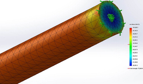
Results of the FEA simulations are presented in . Results were confirmed by one-tailed student t-test conducted at the 95% confidence (p = 0.37, α = 0.05) accepting the Null Hypothesis that there is no significant difference between the average and simulated tensile strengths. Shown in is the stress distribution in terms of Von Mises stresses for the strongest stent (sample ID #4) constrained for tensile testing simulating the experimental setup with a UTS of 101 kPa.
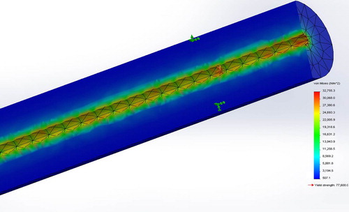
Shown in is the simulated section view of Von Mises stresses for Sample ID#4 subjected to circumferential constraint exerted by a blood vessel and a hydrostatic blood pressure of 20 kPa, associated with the systolic pressure of a hypertensive patient (CitationKlabunde 2011). Maximum flow deformation in terms of UTS was simulated to be 37.7 kPa approximately twice the loading pressure indicating that the microfiber can withstand the maximum systolic pressure.
Elongation at break using the nominal isotropic value (ν = 0.3) .vs. empirical Poisson's ratios
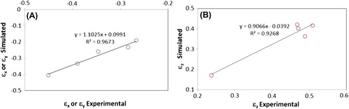
Plotted in are correlations plots for the experimental elongations at break values and the predicted values computed using Eq.3, in both radial and longitudinal directions.. As shown by the slope of the linear model and coefficients of determination (R2) both approaching unity the experimental and simulated values are highly correlated.
Discussion
Throughout this study the assumption of macroscopic isotropy in the FEA analysis and the comparison of the experimental and simulated elongation at breaks has yielded plausible correlations between empirical and theoretical results. In light of the results of these analyses the hypothesis of macroscopic isotropy for the tested formulations can be accepted. A cause for the experimentally measured non-isotropic Poisson's ratios exceeding the value of 0.5 could be hydrogel drying due to the exposure to ambient conditions and non-strained induced shrinkage. Tensile testing and subsequent strain deformation measurements were not conducted in an environmental chamber because it was assumed that measurement time was far shorter than dehydration time. The validity of this assumption needs to be confirmed in subsequent experimental efforts. This hypothesized uncontrolled shrinkage could in turn lead to the diminishing importance of shear stresses assumed to be negligible in the analysis.
For the finite-element-analysis of the hollow fibers, the material was idealized by the analysis software as elastic-plastic with isotropic hardening and Von Mises yielding. In general, the mechanical properties of the relevant composite when chitosan was present in the formulation were considered to be homogenous and isotropic for the matrix. Looking at the stress-strain curves coupled with experimental observations, most of the formulations did not even experience plastic deformation: the samples underwent brittle fracture caused by local crack propagation distributed randomly across the cylinder. Unfortunately, this effect was not simulated by the software. It is not known whether this brittle fracture is an artifact of hydrogel dehydration due to the experiments not being conducted in an environmental chamber, or related to the limited tensile strength of the cross-linked microfiber.
The closest study to this current investigation in terms of hydrogel composition and cross-linked alginate aspect ratio is that of non-hollow microfibers fabricated by means of a fabricated by means of a microfluidic setup (CitationLee et al. 2011). It was reported that the mean value for the Young's modulus of the chitosan–alginate fibers was 0.84 MPa, whereas the calcium alginate fibers had a mean Young's modulus of 1.03 MPa. In contrast, the chitosan–alginate fibers exhibited higher fracture strength of 0.85 MPa compared to 0.66 MPa for the calcium alginate fibers. Although in terms chitosan addition and membrane stiffening findings concur, in the current study chitosan coating led to significantly lower fracture strength or UTS. This discrepancy could be explained by the absence of an additional alginate coating step mobilizing the additional positive charges on the polyelectrolyte and a subsequent sodium citrate treatment step rendering the membrane significantly more fluid. As for the comparison of bare alginate fibers, the 5 fold difference in elasticity (0.84 MPa vs 0.241 MPa ± 0.025 MPa) is due to the difference in force distribution due to the reduced cross-sectional surface area for the hollow as compared to solid fibers. The effect of chitosan coating significantly reducing the elasticity of the alginate base by a factor of 4–5 by conferring compliance to the cross-linked structure is agreement with previous findings (CitationMobed-Miremadi et al. 2013).
The above discussed facts fall in the category of noise while comparing the tensile strength of the alginate microfibers (UTSmax = 0.097 MPa ± 0.026 MPa for sample ID #4) to that of the PLLA-base stents with tensile strengths of 50 MPa and above (CitationDong et al. 2013). In turn due to the versatility of use of alginate in tissue engineering and regenerative medicine, improving the strength of this hydrogel is a very active field of research (CitationYang et al. 2013).
Conclusion
The tensile strength of alginate and ACA hollow fibers were measured and simulated based on the assumption of macroscopic isotropy. FEA analysis was performed based and the elongation at break was compared to the experimental results. While there were no significant statistical differences between the experimental and predicted UTS, the chitosan coating significantly reduced the E and the tensile strength of the hollow fibers. The hypothesis of macroscopic isotropy was also verified by highly correlated theoretical and experimental elongation at break measurements. Before the proposed ACA stent-based delivery method for cardiovascular disease and other regenerative medicine applications can be considered, the following additional investigations are strongly recommended: 1) Performing tensile testing in a humidity controlled environmental chamber to eliminate the uncontrolled shrinkage rate of the hydrogel and re-assess the contribution of shear stresses in the stiffness matrix; 2) changing the formulation to prevent the brittle fracture mode by introducing a plasticizer; and 3) changing the formulation in order to improve the tensile strength of the hollow alginate and ACA micro-fibers.
Acknowledgments
Mechanical characterization of the films in the Biomedical Devices Laboratory could not have been executed without access to the custom-designed tensile tester granted by Dr. Guna Selvaduray.
Declaration of interest
The authors report no declarations of interest. The authors alone are responsible for the content and writing of the paper.
References
- Asimba BO, Shigoli AK, Suthar KJ, Ghantasala MK, Mancini DC. 2012. Numerical Simulation of pH-sensitive Hydrogel Response in Different Conditions. Proceedings of the 2012 COMSOL Conference, Oct 2–5, Boston, MA, pp. 3–5.
- Athyros VG, Kakafika AI, Tziomalos K, Karagiannis A, Mikhailidis DP. 2009. Pleiotropic effects of statins–clinical evidence. Curr Pharm Des 15:479–489.
- Baim DS, Braden G, Heuser R, Popma JJ, Cutlip DE, Massaro JM, et al. 2004. Utility of the Safe-Cross-guided radiofrequency total occlusion crossing system in chronic coronary total occlusions. Am J Cardiol. 94:853–858.
- Barralet JE, Wang L, Lawson M, Triffitt JT, Cooper PR, Shelton RM, et al. 2005. Comparison of bone marrow cell growth on 2D and 3D alginate hydrogels. J Mat Sci Mater Med. 16:515–519.
- Bartkowiak-Jowsa M, Będziński R, Szaraniec B, Chłopek J. 2011. Mechanical, biological, and microstructural properties of biodegradable models of polymeric stents made of PLLA and alginate fibers. Acta Bioeng Biomech. 13:21–28.
- Candiello J, Singh SS, Task K, Kumta PN, Banerjee I. 2013. Early differentiation patterning of mouse embryonic stem cells in response to variations in alginate substrate stiffness. J Biol Eng. 7:9.
- Chang TMS. 2013. Selected Topics in Nanomedicine Singapore: World Scientific Publishing Co.
- Djomehri S, Mobed-miremadi M, Keralapura M. 2013. Modeling diffusivity through alginate-based microfibers: a comparison of numerical and analytical models based on empirical spectrophotometric data. J Memb Separ Tech. 74–87.
- Dong J, Liao L, Fan Z, Li S, Lu Z. 2013. Totally Bioresorbable Stents with Improved Properties for Cardiovascular Disease. Plastics Research Online. Available from: <http://www.4spepro.org/view.php?article = 005019-2013-08–16 & category = Bioplastics>. [16 December 2013].
- Dowling NE. 1993. Mechanical Behavior of Materials: Engineering Methods for Deformation, Fracture and Fatigue Englewood Cliffs, NJ: Prentice-Hall.
- Guan YJ, Zhu N, Cooper D, Chen XB. 2011. ‘Characterization of 3D Alginate Scaffolds Using Micro-CT’, Proceedings of the 34th Canadian Medical and Biological Engineering Conference, University of Saskatchewan, Saskatoon, pp. 1–4.
- Hsiao L, Carr C, Chang KC, Lin SZ, Clarke K. 2013. Stem cell-based therapy for ischemic heart disease. Cell Transplant. 22:663–675.
- Hu Y, Suo Z 2012. Viscoelasticity and poroelasticity in elastomeric gels. Acta Mech Solida Sinica. 25:441–458.
- Imani M. 2013. Simulation of mechanical behaviors of NIR stent in a stenotic artery using finite element method. World Appl Sci J. 22:892–897.
- Jones ML, Martoni CJ, Parent M, Prakash S. 2012. Cholesterol-lowering efficacy of a microencapsulated bile salt hydrolase-active Lactobacillus reuteri NCIMB 30242 yoghurt formulation in hypercholesterolaemic adults. Br J Nutr. 107:1505–1513.
- Kang MK, Huang R. 2011. Swelling-induced instability of substrate-attached hydrogel lines. Int J Appl Mech. 3:219–233.
- Keehan E, Gergely V. 2009. ‘Catheter and specialty needle alloys’, Materials & Processes for Medical Devices Conference & Exposition, Aug 10–12, Minneapolis, pp. 10–12.
- Klabunde R. 2011. Cardiovascular Physiology Concepts, 2nd ed. Philadelphia, PA: Lippincott Williams & Wilkins, pp. 60–92.
- Lakes RS, Wineman A. 2006. On Poisson's ratio in linearly viscoelastic solids. J Elast. 85:45–63.
- Lee BR, Lee KH, Kang E, Lee SH. 2011. Chitosan-alginate microfibers generation on a microfluidic chip and encapsulation of HEPG2 cells 15th International Conference on Miniaturized Systems for Chemistry and Life Sciences, Oct 2–6, Seattle, WA, pp. 1125–1127.
- McGinty B. n.d., Continuum Mechanics: Von Mises Stress. Available from: <http://www.continuummechanics.org/cm/vonmisesstress.html>. [13 April 2013].
- Mobed-Miremadi M, Nagendra RK, Ramachandruni SL, Rook JJ, Keralapura M, Goedert M. 2013. Polystyrene microsphere and 5-fluorouracil release from custom-designed wound dressing films. Progr Biomater. 2:1.
- Onuma Y, Serruys PW. 2011. Bioresorbable scaffold: the advent of a new era in percutaneous coronary and peripheral revascularization?Circulation. 123:779–797.
- Prendergast PJ, Lally C, Daly S, Reid AJ, Lee TC, Quinn D, Dolan F. 2003. Analysis of prolapse in cardiovascular stents: a constitutive equation for vascular tissue and finite-element modelling. J Biomech Eng. 125:692–699.
- Russo R, Malinconico M, Santagata G. 2007. Effect of cross-linking with calcium ions on the physical properties of alginate films. Biomacromolecules. 8:3193–3197.
- Semmling B, Nagel S, Sternberg K, Weitschies W, Seidlitz A. 2013. Development of hydrophobized alginate hydrogels for the vessel-simulating flow-through cell and their usage for biorelevant drug-eluting stent testing. AAPS PharmSciTech. 14: 1209–1218.
- Shan Y. 2011. Viability of Microencapsulation of E. coli DH5 for Urea Removal Using Inkjet Bio-printing. Available from: <http://www.engr.sjsu.edu/ges/media/pdf/mse_prj_rpts/fall2011/VIABILITY_OF_MICROENCAPSULATION_OF_E.COLI_DH5_FOR_UREA.pdf>. [16 December 2013].
- Simpliciano C, Clark L, Asi B, Chu N, Mercado M, Diaz S, et al. 2013. Cross-linked alginate film pore size determination using atomic force microscopy and validation using diffusivity determinations. J Surf Eng Mater Adv Technol. 3:1–12.
- Strauss BH, Goldman L, Qiang B, Nili N, Segev A, Butany J, et al. 2003. Collagenase plaque digestion for facilitating guide wire crossing in chronic total occlusions. Circulation. 108:1259–1262.
- Tamayol A, Akbari M, Annabi N, Paul A, Khademhosseini A, Juncker D. 2013. Fiber-based tissue engineering: Progress, challenges, and opportunities. Biotechnol Adv. 31:669–687.
- World Health Organization. 2013. The 10 leading causes of death in the world, 2000 and 2011 Available from: <http://www.who.int/mediacentre/factsheets/fs310/en/index.html>. [16 December 2013].
- Yang CH, Wang MX, Haider H, Yang JH, Sun JY, Chen YM, et al. 2013. Strengthening alginate/polyacrylamide hydrogels using various multivalent cations. ACS Appl Mater Interfaces. 5:10418–10422.
- Zhao L, Zhang Z. 2004. Mechanical characterization of biocompatible microspheres and microcapsules by direct compression. Artif Cells Blood Substit Biotechnol. 32:25–40.