
 ?Mathematical formulae have been encoded as MathML and are displayed in this HTML version using MathJax in order to improve their display. Uncheck the box to turn MathJax off. This feature requires Javascript. Click on a formula to zoom.
Abstract
A small-scale optical device incorporated with an optical nano-antenna is designed to operate as the remote artificial eye using a tiny conjugate mirror. A basic device known as a conjugate mirror can be formed using the artificial eye device, the partially reflected light intensities from input source are interfered and the 3D whispering gallery modes formed within the ring centers, which can be modulated and propagated to the object. The image pixel is obtained at the center ring and linked with the optic nerve in the remote area via the nano-antenna, which is useful for blind people.
Introduction
Artificial eyes are among the most important organs which can give the blind person sight ability. Normally, the bionic eye has become the basic artificial eyes for the blind and depends on the circumstances surrounding the loss of sight. The retinal prostheses are the most prevalent visual prosthetic under developments, in which the candidates for visual prosthetic implants find the most successful procedure if the optic nerve is developed prior to the onset of blindness. Persons born with blindness may lack a fully developed optical nerve, which typically develops prior to birth. Visual prosthetics are being developed as a potentially valuable aid for individuals with visual degradation, where all other efforts remain investigational, and most have not yet employed to any clinical use in patients.
Artificial vision device has become the important instrument for various applications, for instance, surveillance, blind people, robot, eyesight problem, especially, for the humanoid robotic applications. Results in both design and practical works have been reported (CitationWeiland and Humayun 2006, CitationJeong et al. 2006, CitationHe et al. 2013, CitationTamee et al. 2013a) and the potential applications have been developed (CitationDobelle 2000, CitationKaniusas et al. 2011, CitationTamee et al. 2013b), where one aspect of results has shown the feasibility of using artificial eyes (vision) for human eye replacement (CitationJonas et al. 1992, CitationJonas et al. 2004). The possibility of vision image connection between optic nerve and brain cells can be realized (CitationCavallini et al. 2013), which is useful for realistic artificial eye use. The use of THz technology can be adopted to employ with human tissue penetration and investigation, where there are some works reported the use of THz for imaging and investigations (CitationZainol et al. 2013, CitationTamee et al. 2013). An interesting result is the use of whispering gallery mode (WGM) of light within a tiny optical device, where the 3D image basic device, known as a conjugate mirror, can be easily constructed using the WGMs of light within a PANDA ring circuit (CitationUomwech et al. 2010, CitationYupapin 2013). The THz WGMs can also be generated, and used to form the 3D image and linked to the optic nerve and brain (CitationSarapat et al. 2013). Using this method, the artificial vision (bionic eyes) can be constructed and realized.
Extrasensory perception (ESP) is involved in the reception of information, which is not gained through the recognized physical senses but it is sensed by the mind. Till date, the scientific community rejects the ESP due to the absence of an evidence base, the lack of a theory which could explain the ESP, and the lack of experimental techniques which can provide reliably positive results [15, 16](CitationOptic nerve, Wikipedia, Searched by November 2013, CitationWeebly - etenetwork.weebly.com, Searched by November 2013). This article presents the conceptual model of the ESP of vision, which is based on the simulation results. However, the device parameters and materials can be fabricated and the proposed model for 3D artificial vision can be formed, using the conjugate mirrors and nano-antenna (CitationThammawongsa et al. 2012). The basic concept of small-scale optical system using a conjugate mirror is described. Such a device is formed by a PANDA ring resonator as a foundation, and will be a useful source for readers in many areas. In practice, when the realistic device parameters are used, such a device can be fabricated and implemented, especially, for artificial eye applications, which can therefore be available for various works in the near future. In simulation, the partially reflected light intensities from two device ends are interfered and the 3D WGMs within the small ring constructed by four-wave mixing of waves. The 3D image (pixel) can be linked to the optic nerves (optic chiasm) via the nano-antenna. The scanning image for large area is also available, where finally the 3D images can be constructed and linked to the human chiasm and brain cells for perceptions.
Background
WGMs of waves were first explained by Lord Rayleigh to excite mechanical WGMs within micro-resonators [13, 18](CitationYupapin 2013, CitationYupapin and Phatharacorn 2013). In this paper, the principle of WGMs within a PANDA ring resonator is used to form the artificial eye model, and is analytically solved. However, the simulation results are obtained and presented using the experimental simulation technique, which will be demonstrated in the following section. To obtain the required information, the electromagnetic field in the form of WGM is described and discussed using the specific conditions, where finally, the finite difference time domain (FDTD) method is used to obtain the results, the FDTD details are found in the references [19, 20](CitationOptiFDTD 2008, CitationTaflove and Hagness 2005). The artificial eye with nano-antenna system is modeled as shown in . It is formed by a cascaded ring resonator system, which is a complementary PANDA ring resonator.
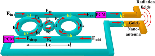
Figure 1. Schematic diagram of 3D image transmission system using ring conjugate mirror connected by a transmitter (antenna), where Ei: optical fields, ki: coupling coefficients, Ein: input port (field), Eth: through port, Edrop: drop port, Eadd: add port, Lx: length in μm.
When a Gaussian pulse is input into the device input port, the electromagnetic field in the form of WGM can be described and generated within a PANDA ring circuit using the Maxwell's equations [14, 18](CitationSarapat et al. 2013, CitationYupapin and Phatharacorn 2013), where ρ (rho) is the radial distance and φ is the angle measured counterclockwise from the polar axis to the ray from the origin.
Using the separation method, Maxwell's wave equation can be obtained and split into two equations (i) radial and (ii) azimuthal components. Solutions of this equation are the complex exponentials, which are given by ![]() . The radial equation is the Bessel's equation, is given as.
. The radial equation is the Bessel's equation, is given as.
The solutions of Bessel's equation are the Bessel's functions of the first Jm and the second Ym kinds, respectively. As the second function is singular at the origin, only the first kind function is retained inside the ring, whereas outside the ring both the functions are well behaved and must be retained. The Hankel functions are linear superposition of two Bessel function solutions corresponding to outward, ![]() and inward
and inward ![]() propagating cylindrical waves. The analysis of wave arriving at the resonator from the radial horizon is not considered here, and thus only the Hankel function of the first kind, Hm1, is retained. The WGM solution within the PANDA ring can be solved and obtained using the cylindrical coordinate, in which the solutions are given via the Bessel's functions [18](CitationYupapin and Phatharacorn 2013).
propagating cylindrical waves. The analysis of wave arriving at the resonator from the radial horizon is not considered here, and thus only the Hankel function of the first kind, Hm1, is retained. The WGM solution within the PANDA ring can be solved and obtained using the cylindrical coordinate, in which the solutions are given via the Bessel's functions [18](CitationYupapin and Phatharacorn 2013).
where,
and
![]() is the solution in cubic equation, and n0 is the refractive index, A0 and w are the Gaussian pulse parameters, and
is the solution in cubic equation, and n0 is the refractive index, A0 and w are the Gaussian pulse parameters, and
In , the WGMs of light can be formed when the maximum optical fields, Emax(ρ,ϕ) in Equation (2), satisfy the resonant condition that are located at the center rings R1, R2, and R3. From Equation (3), all parameters can be numerically solved and results are obtained via FDTD and MATLAB programs. The required WGMs are described by the following details; R1 and R2 WGMs represent the incident light beams to the target object, where the reflected beams are interfered in the conjugate mirror, in which the 3D image is constructed using the four-wave mixing method within the R3 ring, where the 3D image (a pixel) is formed. In application, the WGM switching directions can be controlled and the required direction is obtained. In , the center WGM output is formed the reference signal, while the coupling signals between through and drop ports are transmitted by the nano-antenna.
Simulation results
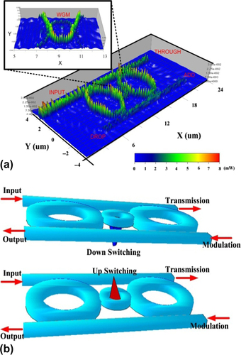
In simulation, a 100 fs Gaussian pulse is modulated by a 200-THz (1012 Hz) carrier and incident via the PANDA ring input port into the artificial eye model. The vertical waveguide thickness and material composition is considered by computing the effective refractive index, neff, for the fundamental mode at λ = 1.55 μm. In the vertical direction, each waveguide structure is 0.45 μm thick, with vertical core thicknesses of 0.3–0.5 μm, and the neff value is between 3.2 and 3.4. The parameters are obtained using the practical material parameters. The used material is an InGaAsP/InP [14](CitationSarapat et al. 2013). Therefore, the waveguide core, with refractive index n1 = 3.14, is bordered on each side by air (n2. = 1). The parameters of the add-drop optical multiplexer and the side rings on the left- and right-hand sides of the three cascade ring radii are R1 = R2 = 3 μm, the center ring radius is R3 = 1 μm. The coupling coefficients are κi = 0.6, i = 1–6, the effective core area of the waveguides is Aeff = 0.25 μm2, and the waveguide loss coefficient is α = 0.1 dBmm−1, n2 = 1.3 × 10− 17 cm2/W. In this article, the simulation results are achieved using the Optiwave FDTD and MATLAB programs [19, 20](CitationOptiFDTD 2008, CitationTaflove and Hagness 2005). The WGM result is obtained via Optiwave as shown in . The WGMs can be generated and controlled to localize within center ring and two-side rings, which depends on the used parameters and conditions, where the other input signals can be modulated by the ADD port input signals. A pixel of artificial vision is designed to produce the 3D images (visual signals), where the image (data signal) can be transmitted by modulating the signal amplitude of the various wavelengths. The switching direction can be controlled by the input signal via the add port (modulation) as shown in .
Figure 2. Schematic of WGM switching signals, where (a) 3D whispering gallery mode of light within a 3CR (3 cascaded rings (3CR) waveguide, (b) the switching signals (up or down) can be controlled using the modulated signal input.
In , the WGMs are obtained and shown by peaks (red color) and valleys (blue color), respectively. The WGM peak signals are incident to the target object, in which the reflected light beams from the target object is interfered within the artificial eyes, in which the 3D image information is formed by the four-wave mixing of waves as shown by WGMs in the valleys. To confirm the 3D image construction, the four-wave mixing output is required for each pixel, where one of them is plotted and shown in , which is the symmetrical interference signals under four-wave mixing and gives a symmetrical output signal. The output signals are modulated and transmitted via the antenna to the require destination as shown in . The image information is then input into the receiving antenna and directed to the artificial eyes, which is connected to the optic nerves and chiasm, where finally, the 3D image can be recognized by the brain cells.
Figure 3. Simulation results of two-dimensional plot and nicely demonstrates the phase conjugate normalized intensities (center ring results) from top are 30, 32, 33 and 36 fs (10 − 15 s), in which different switching directions are applied (red: peaks and blue: valleys).
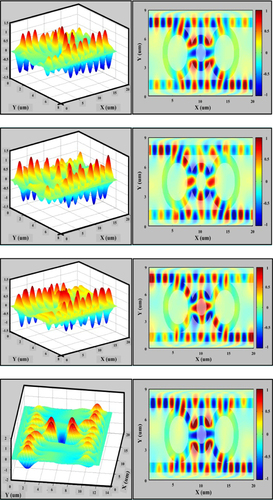
Figure 4. Shows the two-dimensional plot and nicely demonstrates the phase conjugate intensity and wavelength in arbitrary units.
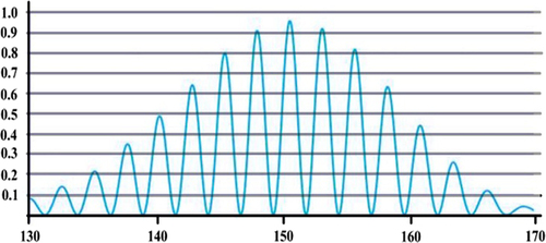
Figure 5. An implanted optical 3CR chip design system for a remote artificial eye system, where (a) image construction, (b) transmitter, (c) receiver, optic nerve and optic chiasm connection.
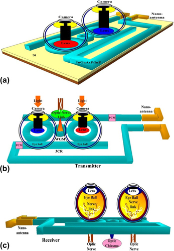
From , the proposed system is a micro-scale device, which is about 100 μm and 10 times of human hair dimension. Such a tiny device can be fabricated and embedded on chip, which can be connected to the optic nerves/cells. In operation, the 3D pixels in the form of WGM signals can be generated and controlled using the system in , for instance, the WGM switching signals can be selected to the required directions, that is, switching up or down direction, which can be useful for 3D image information connection as shown in [21](CitationBem 1967), where the image information is constructed and represented by R3 WGMs. This information is then connected by the transmitter to the receiver and optic nerve cells and chiasm as shown in .
The ESP conceptual model can be constructed and operated using the remote artificial eyes, in which the imaging transmission (perception) can be functioned by the nano-antenna, where the 3D image information can be modulated and transmitted to the receiving antenna. The modulated image signals are entered into the receiving artificial eyes and the image information connected directly to the brain cells, which is faster than the normal image transmission device, for instance, a multimedia device. The sequent images can be constructed and transferred via the transmitted nano-antenna, where finally, the required images can be constructed and seen by the end users via the received nano-antenna. The speed of transferring image depends upon the user-switching ability; however, in application, large volume of images can be stored by the personal memory device (chip), which can be loaded and recovered by the users later on.
Conclusion
The ESP model using remote artificial eyes has been proposed, in which a micro-ring resonator system has been designed and used as a small-scale artificial vision device (pixel) for artificial eye applications. A single point 3D image of the target object is presented by an image forming within the device and can be constructed for large-scale images and linked to the optic nerve and brain cells, which can be used for artificial vision. To confirm the 3D image output, such a required result of the 3D image is shown by the output result of the WGM signals in terms of four-wave mixing concept, which is confirmed. In application, the large area of devices can be formed and constructed by a thin-film technology, which can be used for imaging devices, artificial eyes and humanoid robot eyes, in which the eye sight and blindness problems can be investigated and solved. Moreover, such a conceptual model can be formed and linked by electromagnetic waves and signals via antenna that can be external installation or embedded on chip into the required users, which can be useful for ESP investigations. The proposed system is constructed using the electromagnetic wave propagation, which can be useful with full ranges of ESP applications (CitationAli and Yupapin 2014, CitationYupapin et al. 2014, CitationPantian and Yupapin 2013), where the use such as telepathy, clairvoyance, precognition, and psycho-kinesis can be investigated by the similar manner.
Acknowledgment
The authors would like to acknowledge the King Mongkut's Institute of Technology Ladkrabang (KMITL), Bangkok 10520, Thailand for giving the research facilities.
Declaration of interest
The authors report no declarations of interest. The authors alone are responsible for the content and writing of the paper.
References
- Ali J, Yupapin PP. 2014. Micro-cloud computing system by human quantum computer. J Biosens Bioelectron. 5:e127.
- Bem JD. 1967. Self-perception: an alternative interpretation of cognitive dissonance phenomena. Psychological Review. 74: 183–200.
- Cavallini GM Forlini M, Gramajo AL, Brombin A, Torli G, Volpini E, Forlini C. 2013. Optic nerve aplasia and microphthalmos: a case report. J Genet Syndr Gene Ther. 4:000175–1–3.
- Dobelle WH. 2000. Artificial vision for the blind by connecting a television camera to the visual cortex. ASAIO Journal. 46:3–9.
- He Q, Liu J, Yang B, Dong Y, Yang C. 2013. Fabrication and characterization of biologically inspired curved-surface artificial compound eyes. J Microelectromech S. 22:4–6.
- Jeong KH, Kim J, Lee LP. 2006. Biologically inspired artificial compound eyes. Science. 312:557–561.
- Jonas JB, Martus P, Horn FK, Junemann A, Korth M, Budde WM. 2004. Predictive factors of the optic nerve head for the development of progression of glaucomatous visual field loss. Invest Ophth Vis Sci. 45:2613–2618.
- Jonas JB, Schmidt AM, Muller-Bergh JA, Schldrzer-Schrehardr UM, Naumann GOH. 1992. Human optic nerve fiber count and optic disc size. Invest Ophth Vis Sci. 33:2012–2018.
- Kaniusas E, Varoneckas G, Mahr B, Szeles JC. 2011. Optic visualization of auricular nerves and blood: optimization and validation. Instrumentation and Measurement, IEEE Transaction on. 60:3253–3258.
- Optic nerve, Wikipedia, Searched by November. 2013.
- OptiFDTD by Opti-wave Corporation Company, Version 8.0, single license, 2008.
- Pantian S, Yupapin PP. 2013. THz Rabi frequency oscillation for human consciousness/sub-consciousness detection probe use. J Biosens Bioelectron. 4:e126.
- Sarapat N, Frank TD, Yupapin PP. 2013. Conjugate mirror design and simulation using a nonlinear coupling microring circuit. J Nonlinear Opt Phys. 22:1350024–1.
- Taflove A, Hagness SC. 2005. Computational Electrodynamics: The Finite-Difference Time-Domain Method. Boston: Artech House.
- Tamee K, Chaiwong K, Yothapakdee K, Yupapin PP. 2013a. Brain signal monitoring and encoding for humanoid robots use. J Biosens Bioelectron. 4:13e–124.
- Tamee K, Chaiwong K, Yothapakdee K, Yupapin PP. 2013b. Psychiatric investigation using WGMs using a nonlinear microring circuit. J Innovative Optical Health Sciences. 6:1350044–1–7.
- Thammawongsa N, Moongfangklang N, Mitatha S, Yupapin PP. 2012. Novel nano-antenna system design using photonic spin in a PANDA ring resonator. Progress In Electromagnetics Research Letters. 31:75–87.
- Uomwech K, Sarapat K, Yupapin PP. 2010. Dynamic modulated Gaussian pulse propagation within the double PANDA ring resonator. Microw Opt Technol Lett. 52:1818–1821.
- Weebly - etenetwork.weebly.com, Searched by November. 2013.
- Weiland JD, Humayun MS. 2006. Intraocular retinal prosthesis. IEEE Engineering in Medicine and Biology Magazine. 25:60–66.
- Yupapin PP, Pantian S, Ali J. 2014. Novel design Rabi oscillation system for human quantum life detection probe. Life Sci J. 11:235–243.
- Yupapin PP, Phatharacorn P. 2013. Analytical solution of whispering gallery mode of light in a PANDA ring resonator. Preparing manuscript (Private Communication). 15 pages.
- Yupapin PP. 2013. Nonlinear coupling effects of waves in a panda ring. Science Discovery. 1:1–5.
- Zainol FD, Thammawongsa N, Mitatha S, Ali J, Yupapin PP. 2013. Nerve communication model by bio-cells and optical dipole coupling effects. Artif Cells Nanomed Biotechnol. 41: 368–375.