
Abstract
Introduction
The anatomy of the vertebral artery (VA) at the cranio-vertebral junction is significantly different from the straightforward course in the transverse foramina from C6 to C2 vertebrae. Recent methods of fixation of C1 and C2 vertebrae due to different pathologies (trauma, tumors, or infection) are based on trans-articular procedures or direct screws for C1 and C2. These methods of fixation depend on a detailed knowledge of the osseous anatomy of C1 and C2 vertebrae, in addition to their relation to the vertebral artery.
Aim
The aim of this work was to obtain anatomical measurements of the vertebral artery segment between C1 and C2 to be considered during cranio-vertebral approaches.
Materials and methods
Twenty five osseous specimens of C1 and C2 vertebrae were obtained from anatomy museum and ten adult cadaveric specimens were also studied. The anatomical measurements of vertebral artery were tabulated and graphically presented. The anatomical measurements obtained from C1 and C2 vertebra were statistically analyzed.
Results
Twenty five osseous specimens of C1 and C2 vertebrae were examined carefully. The anatomical measurements obtained from C1 vertebra were statistically analyzed. Different measurements of the vertebral artery groove including its length and diameter in addition to the distance between each of the medial and lateral edges of the inner and the outer cortices of the vertebral groove to the posterior tubercle of atlas respectively were measured and tabulated. The segment of VA between C1 and C2, the third and the fourth parts of vertebral artery were dissected in ten adult cadaveric specimens. The anatomical measurements of vertebral artery were tabulated and graphically presented.
Conclusion
The vertebral artery adopts a serpentine course in relationship to C1 and C2 vertebrae, making it susceptible to injury during surgical procedures in this region. Comprehensive knowledge of the surgical anatomy is essential before performing surgery around the vertebral artery.
1 Introduction
The atlas vertebra (C1) has unique anatomy due to the absence of the vertebral body and its ring-like shape which makes it different from other cervical vertebrae. Absence of the vertebral body is replaced by two lateral masses that are joined together by a short anterior arch and a long posterior arch. At the level of C1 vertebra, the vertebral artery (VA) exits from the transverse foramen and courses in the vertebral artery groove lateral to the spinal canal and posterior to its lateral mass.Citation1,Citation2
The lateral mass of the atlas is anatomically ideally suited for screw fixation to achieve C1–C2 arthrodesis. The increasing use of lateral mass screw placements for atlanto-axial arthrodesis has made it necessary to have a detailed knowledge of the anatomy of C1 vertebra for optimal placement of the screws.Citation3
The vertebral artery is classically subdivided into four segments, the first segment extends from its origin from the subclavian artery to C6 transverse process (V1), the second segment extends from C6 to C1 transverse processes (V2), the third segment extends from C1 to the foramen magnum (V3), and finally, the fourth segment extends intradurally from the foramen magnum to vertebrobasilar junction (V4). Citation4 The location of the vertebral artery on a groove on the superior surface of the posterior arch of atlas makes it vulnerable to injury during surgical procedures in this region.Citation5
In addition, this groove may be converted into a foramen by a bony bridge extending from the lateral mass to the posteromedial margin of the groove. Anatomical variations affecting the groove and foramina of the atlas may be the cause of disturbances of the normal function of the vertebral artery.Citation6 Various terms, including arcuate foramen,Citation7,Citation8 foramen sagitalle, foramen atlantoideum posterior, Kimmerle’s variant,Citation9 foramen arcuale, foramen retroarticular superior, canalis vertebralis, retroarticular vertebral artery ring, retroarticular canal and retrocondylar vertebral artery ring have been used to describe this foramen.Citation10
Most of the data presented in the literatures regarding the morphometry of the atlas in general and the vertebral artery groove in particular, have been obtained from radiological studies.Citation11,Citation12 Therefore, the present study aimed to create anatomical measurements between the vertebral artery and C1 and C2 to be used in cranio-vertebral approaches.
2 Materials and methods
Twenty five osseous specimens of C1–C2 vertebrae and ten adult head and neck cadaveric specimens were obtained from the anatomy department, faculty of medicine, Alexandria University. These osseous and cadaveric specimens were studied.
All procedures in this study were performed in accordance with the Medical Research Ethics Committee of the Alexandria University.
2.1 Osseous study
The following anatomical measurements were studied on both sides of the twenty five osseous specimens of C1 and C2 vertebrae.
| 1. | Superior articular facet of atlas (SAF) (antero-posterior and transverse diameters). | ||||
| 2. | Inferior articular facet of atlas (IAF) (antero-posterior and transverse diameters). | ||||
| 3. | Groove for the vertebral artery on the upper surface of the posterior arch of atlas (length and diameter). | ||||
| 4. | Vertebral artery groove in relation to pars inter-articularis. | ||||
| 5. | Length of pars inter-articularis. | ||||
| 6. | The distance of the medial and lateral edges of the vertebral artery groove from the posterior tubercle at both the inner and outer cortices of the posterior arch of atlas respectively. | ||||
| 7. | Superior articular facet of axis (antero-posterior and transverse diameters). | ||||
| 8. | The presence or absence of bony spiculae in atlas. | ||||
| 9. | The presence or absence of accessory foramina in atlas. | ||||
Different measurements were recorded, tabulated, and statistically analyzed.
2.2 Cadaveric study
Ten adult head and neck cadaveric specimens (five of them were injected with colored silicon to facilitate exposure of the artery) were subjected to the following:
A midline posterior incision was done extending from the inion down to C7 vertebra. After blunt dissection of trapezius, splenius capitis, and semispinalis capitis muscles, the suboccipital triangle was exposed.
The segment of VA between C1 and C2, the third and the fourth parts of vertebral artery were dissected in the ten adult cadaveric specimens. The anatomical measurements of vertebral artery were tabulated and graphically presented.
The dissection was done to analyze the anatomy of the vertebral artery during its course from C2 foramen transversarium to its entry into the spinal dural canal at the level of C1 vertebra.
The length and diameter of C1 and C2 segment of VA, distance between C1 and C2 segment of VA to superior cervical sympathetic ganglia, diameter of the VA on the vertebral groove on the posterior arch of atlas, distance between the most medial edge of VA groove to the posterior midline of atlas and diameter of the VA in the C1 extradural segment, were measured. In addition to the presence or absence of bony speculae on vertebral artery groove on the posterior arch of the atlas.
Different anatomical measurements were recorded on both sides using a digital Vernier caliper accurate up to 0.01 mm. All measurements were taken twice.
3 Results
3.1 Bony results
Twenty five osseous specimens of C1 and C2 vertebrae were examined carefully. The anatomical measurements obtained from C1 vertebra are statistically analyzed in .
Table 1 The anatomical measurements of C1 in mm (AP: Anteroposterior diameter – TS: Transverse diameter – SAP: Superior articular process – IAP: Inferior articular process – VG: Vertebral groove).
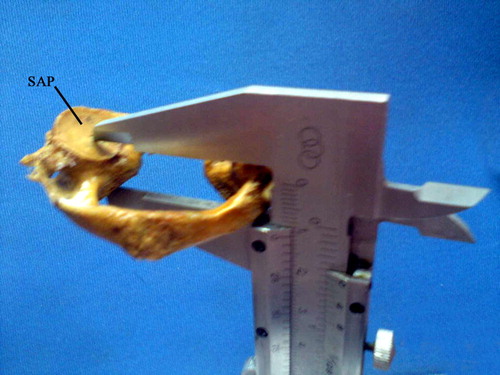
The length of pars interarticularis is measured from the center of the superior articular facet to the center of the inferior articular facet as shown in () (see ).
Figure 1 This figure shows different measurements in both right and left sides mentioned in .

Figure 2 A photograph of an atlas vertebra showing the method of measurement of pars-interarticularis from the center of the superior articular facet (SAP) to the center of the inferior articular facet using a Smith Vernier caliber.
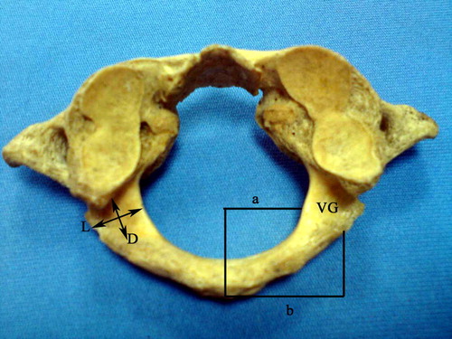
Different measurements of the vertebral artery groove including length, diameter and the distance between the medial and lateral edges of the inner and the outer cortices of the vertebral groove to the posterior tubercle of atlas respectively are illustrated in ().
Figure 3 A photograph of an atlas vertebra showing the length (L) and diameter (D) of the vertebral artery groove (VG) over the superior surface of the posterior arch of atlas. Line (a) corresponds to the distance between the inner cortex of the vertebral groove (VG) to the posterior tubercle of atlas, while line (b) corresponds to the distance between the outer cortex of the vertebral groove (VG) to the posterior tubercle of atlas.
shows that there was a statistically significant difference between the right and left measurements in the AP diameter of SAF and the distance of the outer cortex of the vertebral artery groove from the posterior tubercle of atlas.
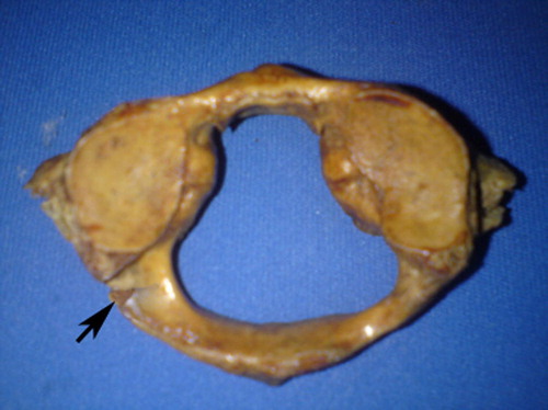
In 8% of C1 osseous specimens, the vertebral artery groove is transformed into an accessory foramen (), while in 10% of C1 osseous specimens, a bony spiculae was seen on the superior surface of the posterior arch ().
Figure 4 A photograph of an atlas vertebra shows the vertebral artery groove is transformed into an accessory foramen on the left side.

Figure 5 A photograph of an atlas vertebra showing bony specula on the superior surface of the posterior arch of atlas (arrow).
The anatomical measurements obtained from C2 vertebra are statistically analyzed in and represented graphically in ().
Figure 6 This figure represents the anatomical measurements of C2 vertebrae mentioned in .
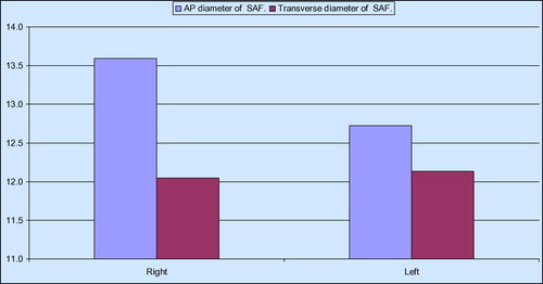
Table 2 The anatomical measurements of C2 in mm (AP: Anteroposterior diameter – TS: Transverse diameter – SAP: Superior articular process – IAP: Inferior articular process).
3.2 Cadaveric results
In all specimens the segment of VA between C1 and C2, the third and the fourth parts of vertebral artery were dissected ( and –) (see ).
Figure 7 A photograph of a right half head and neck specimen exposing a dissected suboccipital region and showing the C1 and C2 segment of the vertebral artery (a) passing between axis (A) and atlas vertebrae (P), and its continuation (b) over the upper surface of the posterior arch of atlas (P). The area between the two arrows shows the diameter of the vertebral artery over the posterior arch of atlas (P). (O: Occipital bone - M: Reflected suboccipital muscles).
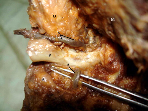
Figure 8 This figure shows different measurements in both right and left sides from the previous table.
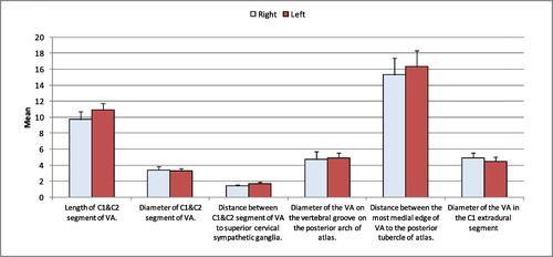
Figure 9 A photograph of right half head and neck specimen showing a dissected suboccipital region showing the C1 and C2 segment of the vertebral artery (a) passing between axis (A) and atlas (P) vertebrae. A divider is put between the two ends of that segment to measure its length. (b: Vertebral artery segment over the posterior arch of atlas).
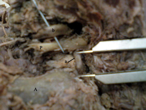
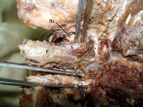
Figure 12 A photograph of a right half head and neck specimen exposing a dissected suboccipital region showing a bony specula (Bs) just close to the medial part of the vertebral artery (b) over the posterior arch of atlas (P). (a: Vertebral artery segment between axis (A) and atlas(P). C2: Second cervical spinal nerve).
The C1 and C2 segment of VA was passing in a vertical direction between axis and atlas vertebrae ( and –). The mean diameter of C1 and C2 segment of the vertebral artery is measured and tabulated in . The mean diameter of the C1 and C2 segment was 3.4 mm on the right side and 3.3 mm on the left side. The mean length of C1 and C2 segment of VA is measured () and tabulated in . The mean on the right side was 9.7 mm while that on the left side was 10.9 mm.
Table 3 The anatomical measurements of vertebral artery in mm in 10 cadavers (VG: Vertebral groove).
The superior cervical sympathetic ganglion was found lateral to C1 and C2 segment of the vertebral artery ( and ). The distance between C1 and C2 segment of vertebral artery and the superior cervical sympathetic ganglion is measured () and shown in . The mean distance on the right side was 1.4 mm while that on the left side was 1.7 mm.
Figure 10 A photograph of a right half head and neck specimen exposing a dissected suboccipital region showing the C1 and C2 segment of vertebral artery (a) passing between axis (A) and atlas (P) vertebrae. A dividal is put between this part of the vertebral artery and the superior cervical sympathetic ganglion(S) to measure the distance between these two structures. (b: Vertebral artery segment over the posterior arch of atlas).
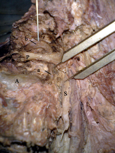
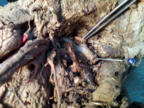
Figure 11 A photograph of a left half head and neck specimen exposing a dissected suboccipital region showing the distance between the medial end of the vertebral artery (injected with latex) over the posterior arch of atlas (b) to the posterior tubercle of atlas vertebrae (P). (a: Vertebral artery segment between axis and atlas – S: Superior cervical sympathetic ganglion – ICA: Internal carotid artery – N: Vagus nerve).
The C1 and C2 segment of VA changed its direction, just above C1 transverse foramen, to run in horizontal course, and then it runs over the upper surface of the posterior arch of atlas ( and –).
The diameter of the vertebral artery over the posterior arch of atlas is measured in () and shown in . The mean diameter on the right side was 4.7 mm while that on the left side was 4.9 mm. There was no statistically significant difference between both sides.
The upper surface of the posterior arch of atlas showed bony specula just close to the vertebral artery over the posterior arch of atlas in 5% of specimens (). Also it showed partial groove in 7% of all cadaveric specimens through which the vertebral artery passes ().
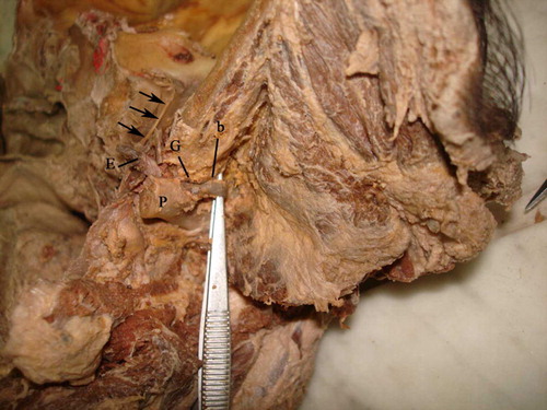
Figure 13 A photograph of a right half head and neck specimen with a midline sagittal cut exposing a dissected suboccipital region. The vertebral artery (b) passes in a partial groove (G) over the superior surface of the posterior arch of atlas (P) then it continues as extradural part of vertebral artery (E) where it pierces the dura mater (arrows).
The mean distance between the most medial edge of the vertebral artery groove over the posterior arch of atlas to the posterior tubercle of atlas vertebrae was 15.0 mm on the right side and 16.0 mm on the left side.
Then the artery passed upward, medially and continued as extradural part of the vertebral artery where it pierced the dura mater (). The diameter of extradural part of VA is measured and tabulated in . The mean diameter on the right side was 4.9 mm and that on the left side was 4.5 mm.
4 Discussion
The location and measurements of vertebral artery groove over the superior surface of the posterior arch of atlas are very important. Several authors addressed the importance of the location of vertebral artery groove during the upper cervical spine surgery.
The critical location of the vertebral artery may complicate the posterior approach during decompressive procedures in the atlantoaxial region.
The data derived from the present study showed the mean length (±SD) of vertebral artery groove was 7.1 mm ± 1.7 on the right side and 7.2 mm ± 2.1 on the left side. While the mean diameter (±SD) of vertebral artery groove was 4.9 mm ± 1.4 on the right side and 5.8 mm ± 1.0 on the left side. The length and the diameter of the groove did not show any statistically significant difference between the right and left sides of atlas in the present study.
Ravichandran et al.Citation13 found that the mean values (±SD) for the groove length on the right side was 7.71 ± 1.16 mm and on the left side, it was found to be 7.49 ± 1.33 mm. Also they found that the mean width (±SD) on the right side was 7.89 ± 1.29 mm and on the left side, it was 8.08 ± 1.37 mm.
It is therefore useful to have a knowledge of the relative position of the vertebral artery on the posterior arch of atlas to determine how much of the posterior arch can be safely exposed. SteiferCitation2 recommended that the dissection of C1 posterior arch should stop 1 cm lateral to midline. An and SimpsonCitation1 also advocated that the posterior aspect of C1 is not be exposed for more than 1.5 cm.
The present study demonstrates the mean distance of the medial edge of the inner cortex of the VG to the posterior tubercle of atlas was 8.6 mm on the right side and 8.7 mm on the left side. The mean distance of the lateral edge of the outer cortex of the VG to the posterior tubercle of atlas was 18.2 mm on the right side, while on the left side it was 16.5 mm. In the present study, there was a significant difference in the distance of the lateral edge of the outer cortex of the VG to the posterior tubercle of atlas between the right and left sides.
Awadalla and FetouhCitation14 found that the distance from the midline to the most medial edge of the vertebral artery groove on the inner cortex of the posterior arch of the atlas (D1) was 8.8 mm with a minimum of 5 mm. Also they found the distance from the midline to the medial most edge of vertebral artery groove on the outer cortex of the posterior arch to be 20 ± 2.3 mm with a minimum of 15 mm.
Naderia et al.Citation15 found that the distance between midline and vertebral artery groove on the outer cortex of C1 posterior arch was 15.05 mm. This means that the posterior tubercle of atlas is a useful landmark during surgical procedures however variations of diameters in both sides could be considered.
Concerning bony spiculae in the present study, it was observed in 10% of dry atlas, while it was present in 8% of C1 osseous specimens; the vertebral artery groove was converted into an accessory foramen. The complete foramen formation when small and constricted may disturb the normal function of the vertebral artery.
Simsek et al.Citation10 classified 158 dried vertebrae on the basis of the morphology of their posterior arches for the passage of the vertebral artery. Of the 158 dry C1 specimens, in nine (5.6%) vertebrae, partial osseous bridging was detected (bilaterally in eight and unilaterally on the left in one). Complete osseous bridging (arcuate foramen) was observed in six (3.8%) vertebrae (bilaterally in one, unilaterally on the left in three and on the right in two).
Anatomical variations of the vertebral artery groove and foramina of the atlas may be the cause of disturbances of normal function of the vertebral artery.
Iatrogenic injury of the third segment of the vertebral artery can occur during surgical procedures. Therefore, the surgeon must possess a detailed knowledge of the anatomy and variability of the V3 segment of the vertebral artery to reduce the risk of complications related to surgical approaches.
The present study revealed the presence of the vertebral artery in all specimens with its two parts: C1 and C2 vertical segment and horizontal segment over the posterior arch of atlas. Duan et al.,Citation16 found the absence of vertebral artery in only one case on the right side from 88 cases. Montechiari et al.,Citation17 reported a case of a patient with the absence of both vertebral arteries.
Arthur et al.Citation18 found that all the segments of the right and left vertebral arteries were extending superiorly from C2 transverse process through the C1 transverse process. Then they proceeded dorsally over the vertebral groove, finally passing through the dura between the foramen magnum and the posterior arch of C1. This agrees with the findings of the present study.
Concerning the mean length of the vertical portion (C1 and C2) segment of VA was 9.7 mm on the right side and 10.9 mm on the left side in the present study. Arthur et al.Citation18 found the mean length of this segment was 9.8 mm on the right side and 11.7 mm on the left side. Also they found this segment was projecting laterally a variable distance before ascending toward the C1 transverse foramen forming a loop. The transition between the C1 and C2 vertical segment and the horizontal segment of vertebral artery after exiting the C2 vertebral foramen is the most likely site of injury when placing C1–2 transarticular screws or C2 pars screws.
Regarding the diameter of the C1 and C2 segment of the vertebral artery, its mean was 3.4 mm on the right side and 3.3 mm on the left side in the present study. There was no statistically significant difference between the right and left sides in the present study. Duan et al.,Citation16 found the diameter of C1 and C2 segment to be 3.49 mm on the left side and 3.24 mm on the right side. Also, there was no statistically significant difference between the right and left sides which was similar to the findings of this study.
Injury to the horizontal third segment of the vertebral artery located in the superior aspect of atlas is a potential hazard of the far lateral approach in a posterior fossa craniotomy. The mean of the diameter of the vertebral artery on the groove of the posterior arch of atlas on the right side was 4.7 mm while on the left side it was 4.9 mm. Arthur et al.Citation18 found the mean diameter of the horizontal loop of the V3 segment was 4.6 mm on the right side and 5.1 mm on the left side. Duan et al.,Citation16 found that the mean diameter of the fourth curve (above the posterior arch of C1) was 3.72 mm on the right side and 3.51 mm on the left side.
In only 2 specimens of the present study, a partial groove was seen on the upper surface of the posterior arch of atlas, while in 3 specimens, bony spiculae were noticed.
Arthur et al.Citation18 found a fully foramen-shaped arterial groove in 5 specimens (4 left sides, 1 right side). Duan et al.Citation16 found variations of C1 in 12 cases of 88 cases, of which 7 cases were congenital arcuate foramen, and 5 cases were congenital defects of posterior arch.
The mean diameter of the vertebral artery in C1 extradural segment in the present study was 4.9 mm on the right side and 4.5 mm on the left side. Duan et al.Citation16 found the diameter of the vertebral artery which goes forward and through foramen magnum (5th curve) to be 2.41 mm on the right side and 2.88 mm on the left side. Sahika Liva Cengiz et al.,Citation19 found that the distance (cm) between the medial tip of the horizontal portion of the vertebral artery and the line passing through the midpoint of the posterior tubercle of the atlas was 1.67 on the right side and 1.67 on the left side. Also Sahika Liva Cengiz et al.Citation19 concluded in their study that the third part of vertebral artery can be easily identified by performing multislice CT scans preoperatively. In addition, their measurements taken in cadavers were corresponding to the same measurements seen on multislice CT scans.
5 Conclusion
Identifying the anatomy and the variations of the vertebral artery and C1 vertebra is necessary in the choice and plan of surgery and raises the accuracy and safety of operations. Imaging anatomy can make up of or enrich the content of regional anatomy, and provide reliable basis for the clinical diagnosis and treatment.
Conflict of interest
The authors declare that they have no conflict of interest.
Notes
Peer review under responsibility of Alexandria University Faculty of Medicine.
Available online 20 June 2014
Related Research Data
References
- H.S.AnJ.M.SimpsonSpinal instrumentation of the cervical spine. Surgery of the cervical spine1994Martin DunitzLondonp.379–400
- E.S.SteiferPosterior atlantoaxial arthrodesis: the Gallie and Brooks techniques and their modificationsTech Orthoped19944348
- T.GuptaCadaveric morphometric anatomy of C1 vertebra in relation to lateral mass screw placementSurg Radiol Anat3072008589593
- B.GeorgeExtracranial vertebral artery anatomy and surgeryAdv Tech Standards Neurosurg272002179216
- T.GuptaQuantitative anatomy of vertebral artery groove on the posterior arch of atlas in relation to spinal surgical proceduresSurg Radiol Anat302008239242
- C.TaitzH.NathanSome observation on the posterior and lateral bridges of the atlasActa Anat1271986212217
- M.HasanS.ShuklaS.SiddiquiPosterolateral tunnels and ponticuli in human atlas vertebraeJ Anat1992001339433
- D.M.StubbsThe arcuate foramen: variability in distribution related to race and sexSpine17199215021504
- A.KimmerlePonticulus posticusRontgenpraxis21930479483
- SerkanSimsekKazimYigitkanliAyhanComertHalil I.AcarHakanSeckinUygurErPosterior osseous bridging of C1J Clin Neurosci152008686688
- H.R.BlackleyL.D.PlankP.A.RobertsonDetermining the sagittal dimensions of the canal of the cervical spine. The reliability of ratios anatomical measurementsJ Bone Joint Surg Br8111999110112
- H.VastardisC.A.EvansEvaluation of cervical spine abnormalities on cephalometric radiographsAm J Orthod Dentofacial Orthopedic10961996581588 (Abstract)
- D.RavichandranK.C.SHanthiV.SrinivasanVertebral artery groove in the atlas and its clinical significanceJ Clin Diagnost Res532011542545
- A.AwadallaF.A.FetouhMorphometric analysis of the vertebral artery groove of the first cervical vertebra (atlas)Pan Arab J Neurosurg13120096770
- S.NaderiaH.ÇakmakçıbF.AcaraC.ArmancT.MertolaM.N.ArdaaAnatomical and computed tomographic analysis of C1 vertebraClin Neurol Neurosurg10542003245248
- S.DuanS.LvFengYeQ.LinImaging anatomy and variation of vertebral artery and bone structure at craniocervical junctionEur Spine J18200911021108
- M.MontechiariA.IadanzaA.FaliniL.S.PolitiMonolateral type I proatlantal artery with bilateral absence of vertebral arteries: description of a case and review of the literatureSurg Radiol Anat102013 1086-4
- J.ArthurM.QuirogaA.RussoV.RussoF.GrazianoA.VelasquezNormal anatomical variations of the V3 segment of the vertebral artery: surgical implicationsJ Neurosurg Spine132010451460
- A.Sahika Liva CengizB.Aynur CicekcibasiC.Demet KiresiA.Yalcın KocaogullarA.Onur CicekA.Alper BayseferAnatomic and radiologic analysis of the atlantal part of the vertebral arteryJ Clin Neurosci162009675678