
 ?Mathematical formulae have been encoded as MathML and are displayed in this HTML version using MathJax in order to improve their display. Uncheck the box to turn MathJax off. This feature requires Javascript. Click on a formula to zoom.
Abstract
Jack-Beams (J-Beams) are used to support discontinued columns that do not extend to lower floors, satisfying space requirements in large stores and workshops. Often large concentrated loads are acting on the laterally unsupported J-Beam top. Built-up I-sections are often used in designing J-Beams. Lateral-torsional buckling (LTB) is crucial in designing J-Beams as it is one of the main requirements in controlling the ultimate bending strength of steel J-Beams carrying loads on top flange. This study investigates the ultimate bending strength of commonly used J-Beams with different sections and classes including slender webs. A numerical model is developed to accurately estimate the ultimate load of J-Beams. The strengths of the selected J-Beams are calculated for different models of unsupported lengths and different section types according to detailed finite element model (FEM) for this type of system. The goal is to investigate the performance of the J-Beams for the selected section types and beam lengths. Single concentrated loads at the top flange of the J-Beams are applied at the FE models. Imperfections of different values are implemented to examine their sensitivity and to find out their effect on the LTB of J-Beams at failure, and hence, their effect on the ultimate strength of J-Beams. The study also introduces simplified procedure and gives recommendations for designing J-Beams using the numerical results of the selected sections.
Introduction
The ultimate bending strength of J-Beams is affected by the Lateral-torsional buckling phenomenon. This phenomenon controls the strength of J-Beams that are not adequately restraint to lateral deflection and twisting out of the loading plane.
For elastic LTB under pure constant bending, the unsupported length is considered to be the J-Beam length (i.e. the J-Beam is laterally restrained at its ends).
The critical buckling moment in the case of pure bending described above is given by [Citation1]:(1)
(1) where L is the length of the J-Beam span which is considered unsupported laterally.
The elastic lateral buckling of J-Beams under vertical loads depends mainly on two parameters: the lateral rigidity of flanges EIy and the torsional rigidity GJ. For long J-Beams the effect of the lateral and warping rigidity Cw decreases and the torsional rigidity dominates. Where E and I are the elastic and shear moduli.
For short compact sections the lateral rigidity provides the main resistance of J-Beams. It is noticed that short J-Beams with slender elements are subjected to local failures under heavy vertical loads. The resistance is further reduced by the yield spread either locally or globally due to excessive stresses.
For other cases of different moment gradients along the J-Beam unsupported length, the use of the moment gradient factor Cb was adopted to Eq. (Equation1(1)
(1) ) to take the effect of different moment distribution along the J-Beam’s unsupported length [Citation1]:
(2)
(2)
The first formula for Cb to find its way into structural design codes is the result of work presented by Salvadori (1955). There is one omission in either of the two formulas just presented Eqs. (Equation1(1)
(1) andEquation2
(2)
(2) ): They do not account for the position of the load on the y-axis of the cross-section [Citation1].
AISC-LRFD [Citation2] proposes a linear transition equation from the end of the elastic region to the plastic moment and scales it with a constant moment gradient factor, Cb, for all ranges of inelastic Beam’s slenderness as follows:(3)
(3)
There are different values for Cb in AISC-LRFD depending on the load conditions of the openings. Apart from the load cases mentioned in AISC-LRFD [Citation2], there are some other cases that the transverse loads act away from the shear center axis. For example, top flange loading on a crane runway girder and bottom flange loading acting on a monorail can be considered in practice [Citation3,Citation4].
J-Beam supporting rafters at the center of the upper flange, as shown in , are subjected to lateral instability.
Fig. 1 J-Beam replacing column.
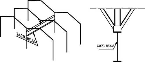
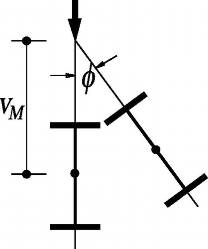
Loads on J-Beam top flange center are overturning and thus remarkably reduce the ultimate capacity. In the following, these cases are investigated on carefully selected J-Beam sections with various lengths. The cross sections contain slender webs to reduce material costs. Furthermore, webs are assumed plain with no stiffeners arranged in order to reduce material and labor expenses ().
Fig. 2 Section torsion.
In this paper, all the studied sections are investigated for single loading at the center of the top compression flange. This loading case is destabilizing with respect to LTB phenomenon.
The selected sections are mono-symmetric of different classes including slender web elements. The J-Beams are simulated using FEA model, including geometrical imperfections in the out-of-plane of J-Beam bending.
The purpose of this paper is to investigate the inelastic LTB behavior for J-Beams loaded on top and having built up sections with slender webs. The effect of lateral imperfections is considered. The upper flanges are laterally free. A concentrated load acts on center of the top compression flange. The overturning moment of this type of loading is considered throughout the analysis.
For this purpose a finite element model based on the software package ANSYS [Citation5] is developed for the nonlinear inelastic LTB analysis of built up mono-symmetric J-Beams with different lengths and web slenderness. Then the results are used to investigate the accuracy of the LTB equations given in the AISC-LRFD provisions, and to propose a simplified design procedure.
Literature review
A comprehensive literature review was given by Mohebkhan [Citation3] covering the advances of LTB related research work.
The differential equation of the elastic, top loaded J-Beam with single forces is given as follows Eq. (Equation4(4)
(4) ):
(4)
(4)
As for double symmetric J-Beams the center of gravity coincides with the shear center at web mid height. The warping constant is CM = Iy .h2/4, where h is the height of the J-Beam. GJ is the torsional rigidity, where . It is noticed that the third coefficient includes M” representing the single load acting vertically on the J-Beam and making the mathematical closed solution very complex. The differential equation is solved numerically and the solution is simplified and is given in Eq. (Equation4
(4)
(4) ) as follows
(5)
(5)
In this equation k is given graphically and includes correction factor representing single loading on the J-Beam acting on top, at the center of gravity or at the bottom [Citation6]. Eq. (Equation5(5)
(5) ) is used later in this paper to verify the numerical accuracy of the finite element model.
Extensive laboratory tests and numerical investigations have been conducted to study the LTB behavior of steel J-Beams by Nethercot et al., Galambos et al. [Citation1], and Trahair [Citation7]. The findings of the above mentioned studies have led to the developments of modern steel design codes in different parts of the world.
Mohebkhan [Citation4] investigated the nonlinear LTB of inelastic castellated J-Beams under moment gradient using a 3D finite element model and showed that the Cb factors given by AISC-LRFD [Citation2] for the inelastic castellated J-Beams are higher than those obtained using the finite element approach. He [Citation4] also investigated the effects of unbraced length and central off-shear center loading (located at center, top flange and bottom flange) on the moment gradient factor in inelastic behavioral zone.
Grondin and Cheng [Citation8] investigated sidesway web buckling of steel J-Beams of laterally supported compression flange numerically and experimentally, including residual stresses and initial imperfection to the numerical model.
Serna et al. [Citation9] proposed a general closed-form expression for determining the equivalent uniform moment factor for any moment distribution and end support conditions, using both finite element analysis and finite difference method.
Choi et al. [Citation10,Citation11], examined inelastic buckling of discretely braced I-girders by diaphragm bracings and torsional stiffness requirements to attain nominal flexural design strengths, incremental nonlinear finite element analyses considering the initial imperfections and residual stresses are conducted, and the effect of torsional bracing stiffness on inelastic lateral torsional buckling was evaluated. They performed series of experimental test results on the inelastic buckling of torsionally braced I-girder system under uniform bending.
Nguyen et al. [Citation12,Citation13], presented an analytical solution, as well as FE-analysis for LTB strength and stiffness requirements of I-girders with discrete torsional bracings under a uniform bending condition.
Assumptions and studied cases
The following assumptions are made:
| • | The material is considered to be idealized perfect elasto-plastic steel. | ||||
| • | The load is acting at mid-span on the top flange. | ||||
| • | The beam is laterally supported only at the ends. | ||||
| • | Flanges are not restrained against warping at supports. | ||||
| • | The load acts eccentrically out of the web plane by eccentricity that is equal to beam imperfection value. | ||||
| • | The flange material is ST 52 (Fy = 360 MPa). | ||||
| • | The web material is either ST 37 (Fy = 240 MPa) or ST 52. | ||||
| • | The modulus of Elasticity E = 210,000 MPa. | ||||
The studied sections are selected considering the following aspects:
| • | Sections and lengths are widely used in practice. | ||||
| • | Structural element (eg. Web, flanges) dimensions conform to available plate sizes and fit the space requirements. | ||||
| • | Economical slender web is selected. | ||||
The selected built-up section dimensions (mm) are given in :
Table 1 Selected sections.
The selected J-Beam lengths are: 10 ms, 15 ms and 20 ms, the lengths conform to practical frame spacing of normal size shops and minimum waste.
Finite element analysis
| (a) | Finite element modeling | ||||
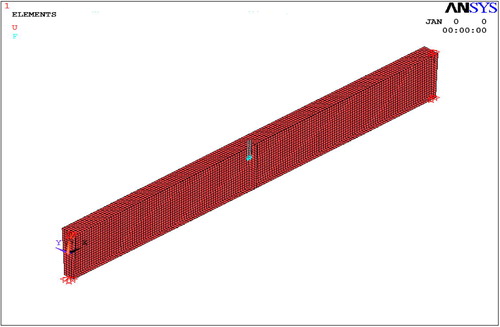
The computations are performed using the Finite Element Software package ANSYS [Citation5]. A total of 9 models are simulated for non-linear inelastic static loading for the three selected sections, covering various J-Beam lengths and different imperfection values. Both geometric and material nonlinearities are considered in a model. Four side shell elements SHELL 181 are used to model the web, flanges (top and bottom) and the stiffeners. This element considers inelastic large strains with six degrees of freedom at each of its four corners. Flanges and webs are modeled with about 5 cm divisions, not exceeding aspect ratio of 1:2.
Full depth stiffener plates are arranged under mid-span load and at reaction force concentration to avoid distortion and local buckling. The support at each end is arranged to facilitate the gradual transition of reaction forces to the web as shown in . Lateral supports are arranged only at support stiffener upper edges allowing warping free J-Beam flanges.
Fig. 3 Model restraints.
The steel is modeled as bilinear isotropic material of modulus of elasticity (E = 210,000 MPa) till the end of elastic behavior. Poisson’s ratio was set to 0.3. Nominal yield stress (Fy) value was specified to be 360 MPa as typically used for built-up sections. Web material may be of steel ST 37 with nominal Fy = 240 MPa.
The iteration procedure selected is the Newton–Raphson method capable of capturing local buckling. Large system deformations are enabled until failure takes place either due to instability (divergence), or due to material failure using Von-Mises criteria at any point in the beam.
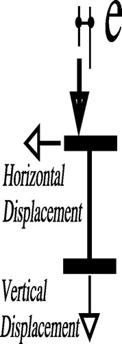
(b) Loading of the model
Single load is applied to the model at the top flange. The load is increased at each step until it reaches the value of the ultimate load, where no equilibrium is possible, or when material failure takes place.
Load- and beam imperfections are replaced by small value opposite disturbing horizontal single loads applied at upper and lower flanges, as shown in . The value of this disturbing force: , where h is the J-Beam height. Thus the imperfection will be represented.
Fig. 4 Loading system.
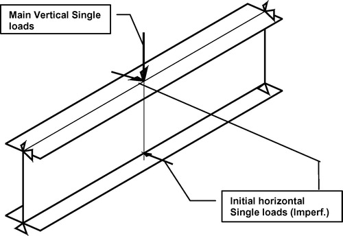
Vertical load is considered to be eccentric loading with respect to the J-Beam centerline by the imperfection value e.
(c) Validation of the finite element model
In order to check the accuracy of the finite element solution procedure, a comparison is made with the respective-, also numerically determined, results given in [Citation6]. The J-Beam is considered elastic with equal flanges, carrying concentrated load at the top flange mid-point. The FEA Eigen-Value is determined numerically using the Block–Lanczos [Citation5] method. The k-values determined using FEA are directly plotted and compared to Eq. (Equation6(6)
(6) ) respective case of single, top loading position, and to elastic flexural and torsional rigidity, along with the J-Beam length and web height according to the following Equation:
(6)
(6)
Using the χ value for each case the factors k described in Eq. (Equation6(6)
(6) ) are compared as shown in .
Fig. 5 Comparison with [Citation6].
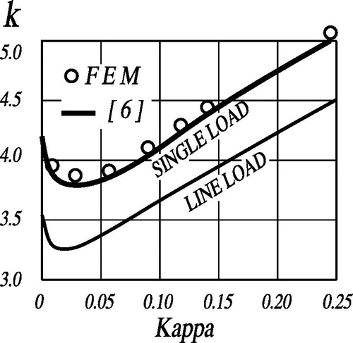
The section type A, with equal flanges, is used to evaluate critical loads for χ values from near zero until 0.25. The results are plotted and directly compared to chart. Good agreement is noticed for χ less than 0.15. At higher χ-values beam length becomes smaller and the system may locally suffer pre-failure due to very high vertical loads. For χ-values less than 0.01, the J-Beam lengths become extremely long and can be considered out of the practical range of the lengths used in beams. The reference curve [Citation6] given in is for loading position at the upper edge of the web that is considered the loading case.
Hence, it is evident that the FEM results remain in acceptable accuracy under the range covered by the FEA procedure. Further from this point, FEA is carried out as non-linear inelastic static loading with large deformation to investigate the inelastic behavior of the models for the selected sections and beam lengths.
Characteristics of numerical analysis (FEM)
The geometrical non-linear inelastic analysis of the model allows for equilibrium under large deformation. It also considers inelastic large strain values. The system may undergo high inelastic deformations and can still accept load increase. The numerically obtained ultimate load may be associated with unrealistic large J-Beam distortions. Therefore, all deformations at each load step are inspected to ensure realistic values. It is crucial to extend the stiffeners at mid section to full section depth, although statically not necessary with respect to the large heights of J-Beams. These stiffeners maintain mid-section shape undistorted during expected excessive rotation angles due to overturning load transmission. P-Delta variations are captured as indicated in .
Fig. 6 Load and displacements.
A J-Beam spanning 10 ms with section type A is selected to demonstrate the variation of horizontal and vertical deformations with respect to load increase as shown in . Each curve relates to a different imperfection value, starting with L/100 until L/5000. Positive values represent lateral sway, negative ones relate to vertical deflection. All cases show no signs of local failure. The ultimate load is found at the curve ends due to instability, where equilibrium is not possible. The curves represent typical results when using Newton–Raphson procedure. It is noted that cases of small imperfection values show post buckling near ultimate load, when comparing with the elastic critical load, for all cases, at about 200 Kn.
Fig. 7 Load-deflection curves.
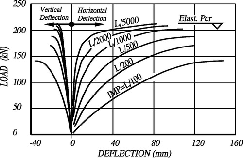
A reasonable lateral imperfection value of L/500 is used throughout the analysis, noting that J-Beams should be carefully fabricated, transported and erected to avoid greater lateral imperfection values.
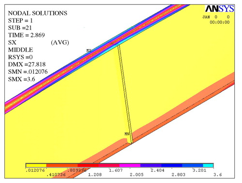
The correctness of the results is confirmed by inspecting a–c.
shows the distribution consistency of longitudinal stresses and in the linear rotation of the middle section is established due to extending the stiffener at mid-span throughout the web height. The importance of the end stiffener is shown in : it should transfer vertical support reaction and, at the same time, allows for free warping of flange end.
Fig. 8a Longitudinal stresses.
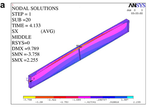
Fig. 8b Lateral deformations.
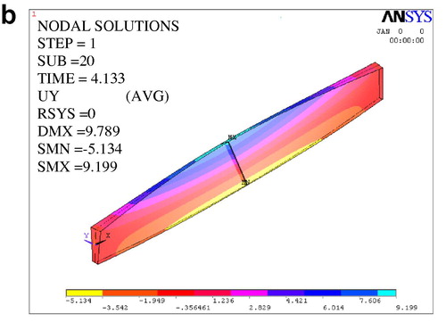
Fig. 8c Longitudinal deformations.
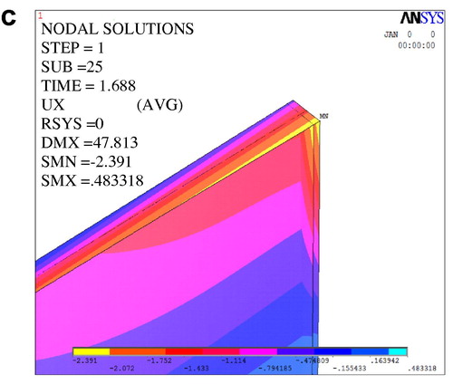
It shows equal and opposite longitudinal deformations of flange end points, note that the upper mid-point has moved about −1.0 cm.
Discussion of the results (FEM)
The analysis results of the selected J-Beams are summarized in . Given are the elastic critical load Pcr, as well as the inelastic ultimate load Pult along with its corresponding maximum sway as absolute- and relative values to span length. Only the 10 m span J-Beams show no post buckling, as its corresponding elastic critical loads are larger than ultimate loads. The ultimate loads reduce drastically with increasing span and/or depth. As stated in Section 1, the flange lateral stiffness governs the ultimate load. The torsional resistance has minor effect. It is evident that the lateral sway, under top load, is almost the same for the same span length irrespective of the J-Beam height. The increase in J-Beam height increases only the ultimate load and has minimum effect on maximum sway values.
Table 2 Ultimate loads and elastic critical loads web and flanges with (Fy = 360 MPa).
Inspecting the normal stresses for each individual case, under each load step, indicated that only flanges suffer high stresses due to lateral deformations. No high normal stresses are found in the web. The analysis is thus repeated for web material having reduced yield stress value equal to 240 MPa. The flanges still yield at 360 MPa. For demonstration the results for this case are tabulated in .
Table 3 Ultimate loads and elastic critical loads (Fy Web = 240, and Fyflanges = 360 MPa).
The small difference in results could be referred to numerical truncation. In general, the results are almost identical and are justified by inspecting and :
Fig. 9 Longitudinal stresses under ultimate load.
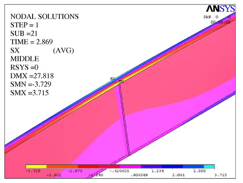
Fig. 10 Equivalent stresses under ultimate load.
It is noticed that web stresses are in general not exhausted. Nevertheless, flanges undergo lateral sway and thus suffer excessive lateral bending edge stresses not transferred to web upper edge that is connected at flange middle.
Parameter study
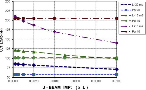
Geometrical imperfections in lateral directions reduce the ultimate capacity of J-Beams remarkably. Their effect could be studied by assuming different values and comparing the results. The numerical analysis is repeated for lateral geometrical imperfections between l/5000 and L/100. Section types A, B and C are chosen for spans 10, 15 and 20 ms respectively. The elastic critical buckling loads (Pcr) are not affected by geometrical imperfections. Their values are calculated and displayed, together with their corresponding ultimate loads in : J-Beams with 10 ms span exert the highest resistance. Their ultimate loads do not remarkably exceed the elastic critical ones indicating little or no post buckling under ultimate load. J-Beams with spans 15 or 20 ms failed under post buckling ultimate loads at all geometrical imperfection values in lateral direction. No local buckling signs are found in all cases. Increasing the value of geometrical imperfections reduces remarkably the ultimate loads for 10 ms span J-Beam, up to 40%. For longer spans increasing imperfections has much less effect.
Fig. 11 Geometrical Imperfections versus Critical and Ultimate loads (Horizontal lines are Pcr).
For each of the studied cases characteristic loads under given lateral deflections are determined. These values are difficult to calculate and not given in code provisions, especially for inelastic considerations. They are useful in design situations where limitation is specified to prevent negative consequences.
Inspecting , we notice that at the largest given lateral deformations of L/100 the maximum load is close to the ultimate one. Limiting the lateral deflection to L/200 or L/500 reduces the maximum load remarkably. Nevertheless, when using these values a factor of safety should be applied according to the corresponding code provisions. All values are based on initial imperfection of L/500 as assumed.
Table 4 Max loads at given additional lateral deformations.
Analytical solution
There are little or no code provisions simplifying safe estimation of lateral sway under lateral torsional buckling displacements. Plotting maximum lateral sway values under ultimate loads makes it possible to establish the simplified analytical solution. shows no or little variation in maximum sway with respect to J-Beam heights.
Fig. 12 Maximum Sway under ultimate loads.
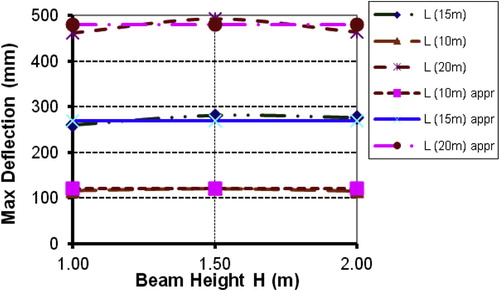
We can explain this phenomenon as follows: The same compression flange exerts approximately the same maximum curvature under ultimate loads. For the same J-Beam length the maximum curvature takes place at approximately the same maximum sway. Its variation with J-Beam heights is not remarkable. The global J-Beam resistance, nevertheless, increases with increasing heights for the same length, since global resistance depends mainly on lateral flange resistance multiplied by the heights. Therefore, we can estimate the maximum sway according to the following simplified formula:(7)
(7) where dmax,ult is in mm, L is in ms.
Approximate and accurate values of maximum displacements are plotted together in . Values are in good agreement.
Eq. (Equation7(7)
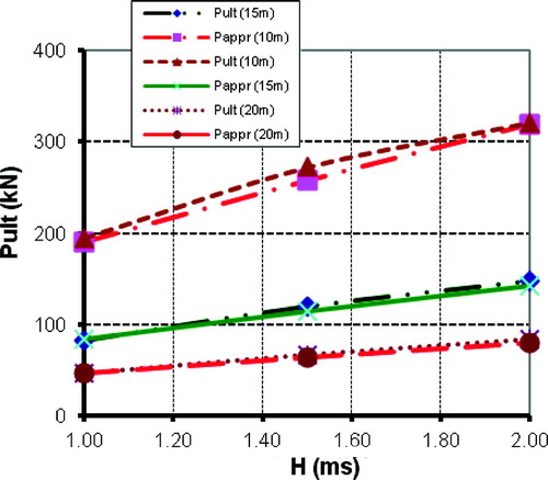
(7) ) is more useful by giving the designer the possibility of estimating lateral sway values under fewer loads than the ultimate ones. shows the possibility of calculating sway values under different load values considering geometrical as well as material non-linearity. First we can use the following formula to estimate the ultimate load represented at the end of each curve in :
(8)
(8)
where H, L are in ms., appr Pult in kN. Accurate and approximate ultimate load values are plotted together in . The approximate formula (Equation8(8)
(8) ) can be considered enough accurate.
Fig. 13 Approximate-versus accurate ultimate loads.
In case the designer considers the expected lateral sway under design load, the corresponding P(δ) at given displacement limit d can be estimated according to the following formula (Equation9(9)
(9) ):
(9)
(9) where d is in mm, L in ms, and appr Pult is calculated according to formula (Equation8
(8)
(8) ). Care should be taken when using Eq. (Equation9
(9)
(9) ), as the adequate safety factor must be applied according to the respective code provisions. Eq. (Equation9
(9)
(9) ) is meant for design approach, accurate loads should be directly interpolated from . For a given actual load the sway can be found using Eq. (Equation9
(9)
(9) ) by iterative approach or by manipulation. Notice that small sway-values limit the load under the elastic buckling load. The previous Eqs. (Equation7
(7)
(7) -Equation9
(9)
(9) ) are limited to the type of sections indicated in .
Conclusion and recommendations
Commonly used J-Beam types, used in normal size workshops, are accurately analyzed using FEM. They have slender webs and carry destabilizing top-loads with no lateral supports. The analysis considered geometrical imperfections to calculate ultimate loads as well as the deformations throughout all load steps until failure took place. Inelastic material and post buckling behavior are considered. J-Beam lengths and corresponding cross sections are carefully selected from numerous actual design cases avoiding local buckling problems. They provide direct and economic solutions with minimum material waste. Design precautions and recommendations are given. Tables and curves are provided for designers to directly use ultimate loads as well as to estimate expected lateral sway under ultimate loads and fewer load values.
In addition, accurate and approximate analytical formulae are given to simplify design and pre-design calculations not given in code provisions. The designer can approximately estimate lateral sway under design working loads directly estimated from ultimate load, along with limitations according to project and safety specifications.
Notes
Peer review under responsibility of Housing and Building National Research Center.
References
- T.V.GalambosA.E.SurovekStructural Stability of Steel Concepts and Applications for Structural Engineers2008John Wiley & Sons IncHoboken, New Jersey
- AISC-LRFDSpecification for Structural Steel Buildings (AISC-LRFD 360-05)2005American Institute of Steel ConstructionChicago (IL)
- A.MohebkhanLateral buckling resistance of inelastic I-beams under off-shear center loadingThin Walled Struct.492011 436–431
- A.MohebkhanThe moment-gradient factor in lateral-torsional buckling on inelastic castellated beamsJ. Constructional Steel Res.60200414811494
- ANSYSUser’s Manual Version 5.4.1998ANSYS Inc201Johnson Road, Houston, PA pp. 15342–1300
- C.F.KollbrunnerM.MeisterKnicken Biegedrillknicken Kippen Theorie und berechnung von Knickstaeben Knickvorschriften1961Springer Verlag
- N.S.TrahairFlexural-Torsional Buckling of Structures1993E&FN SponBoca Raton. London
- Grondin GY, Cheng JJR. Sidesway Web Buckling of Steel Beams. Engineering Journal 1999;(fourth Quarter): 179–169.
- SernaEquivalent uniform moment factors for lateral–torsional buckling of steel membersJ. Constructional Steel Res.622006 580–566
- ChoiInelastic buckling of torsionally braced I-girders under uniform bending: I. Numerical parametric studiesJ. Constructional Steel Res.662010 316–304
- ChoiInelastic buckling of torsionally braced I-girders under uniform bending, II: experimental studyJ. Constructional Steel Res.662010 1137–1128
- NguyenLateral_torsional buckling of I-girders with discrete torsional bracingsJ. Constructional Steel Res.662010 177–170
- NguyenFlexural-torsional buckling strength of I-girders with discrete torsional braces under various loading conditionsEng. Struct.362012 350–337