
Abstract
It has long been known that fire could dramatically reduce the characteristic strength of the reinforced concrete member. A significant effort has been devoted to study the effect of fire on the reinforced concrete members. Most of them were focused on evaluating columns’ fire resistance and provided some recommendations of structural fire resistance. Little attention was paid to the behavior of CFRP strengthened columns after fire.
The main objective of the present work is to study the behavior of reinforced concrete CFRP strengthened columns exposed to fire under axial load experimentally. A furnace and a loading frame had been built to allow the application of the axial load driven from a hydraulic jack on the fired specimens at the same time. Fourteen CFRP strengthened columns with different protection layers subjected to 900 °C for 30 min and axial load at the same time according to ASTM were tested. It can be concluded that the some materials used for protection have low thermal conductivity and good resistance to fire, and CFRP materials used with a appropriate fire insulation can endure elevated temperatures of fire under service loads for more than 70 min.
Although increasing the coating thickness will increase the heat insulation, plain coating of more than 3.0 cm thickness will not be able to stay in place without being reinforced with a suitable wire mesh.
Introduction
Fire in buildings is nearly always resulting from negligence or error. This can cause immense damage in terms of lives and property. With a fire, the main problem to face is the combustibility of the contents and failure of the structure. Extend of ensuing damage depends primarily on the structural performance of the building both during and after the fire. One of the main principles of fire precautions is understand the behavior and characteristics of the building materials during and after the fire crises, to react with them at the new case.
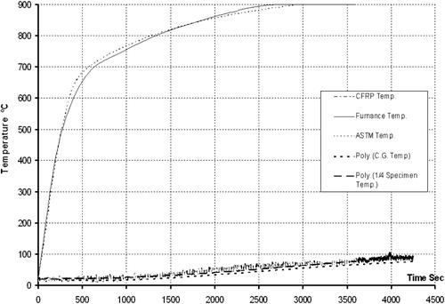
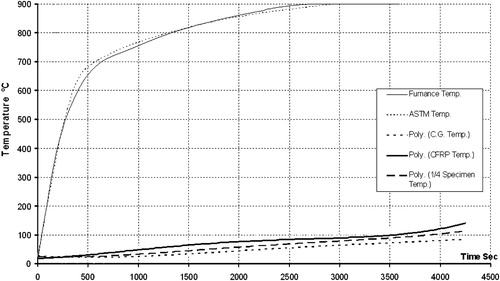
Fig. 19 Temperature at reaching 900 °C of ASTM fire test in CFRP layer.
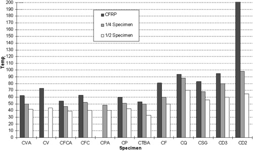
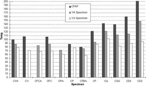
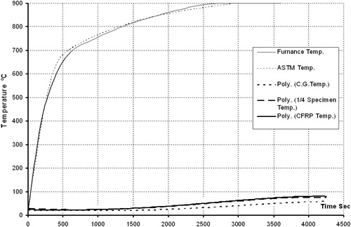
Fig. 20 Temperature at end of ASTM fire test at CFRP layer, specimens.
Studies on reinforced concrete elements were started several years ago for the purpose of updating the fire resistance classifications for these elements. These studies include the development of both experimental and mathematical modelings for the calculation of the fire resistance of concrete elements of various sizes and shapes. Also more attention has been paid to the fundamental fracture properties of concrete at room temperature. But research on these properties under elevated temperatures only started in the late 1970s, and has since become more frequent. The information about these properties is very useful for the design of special concrete structures sustaining various high temperature environments such as nuclear reactor structures, the chemical industry and fire protection.
The behavior of a reinforced concrete structure in fire conditions is governed by the properties of the constituent materials – concrete and steel (reinforcement) – at a high temperature. Both concrete and steel undergo considerable reduction in their strength, physical properties and stiffness by the effects of heating and some of the changes are not recoverable after subsequent cooling. Chemical changes may also occur, especially in siliceous aggregate concrete, due to heating. An understanding of these changes is essential in predicting or assessing the performance of the structure during fire and subsequent cooling.
When a structural component is exposed to devastating fires accidentally for long periods (exceeding fire resistance duration) resulting in high rise of temperature and reduction in strength, the data on residual strength of reinforced concrete members which is defined as “the reduced strength”, are not always available before deciding rehabilitation of any component of the structure damaged due to fire.
The conducted survey of available pertinent research works revealed that there is no available study documenting protection of reinforced concrete strengthened columns using our Egyptian local coating materials, so this research aims to evaluate the suitability of different local Egyptian materials such as Perlite, Ferro-cement, Vermiculate, Feldspar, Quartz, sand glass, and Dry A5 to provide heat protective coating to half scale strengthened loaded columns.
The approach to achieve these objectives is through the following steps:
| I. | Design mortar mixes that have suitable compressive and bond strengths and also have suitable workability in the field. | ||||
| II. | Study the heat transfer through these mixes after being applied on strengthened reinforced concrete elements. | ||||
| III. | Establish experimental relations between different coating types and the residual load capacity after exposure to fire. | ||||
Literature review
This study deals with the effect of elevated temperatures on the strengthened reinforced concrete elements by Carbon Fiber Reinforced Plastic. Many researchers are performing experimental and analytical programs to investigate the response of advanced composite to fire such as Karamoko et al. [Citation1]. They suggested an experimental program for predicting the effect of fire on graphite/epoxy laminates. They subjected the specimens to a propane flame for a period ranging from 3 to 60 s. The specimens showed damage on the exposed face. Viewing a cross section of the burned material under microscope showed progressing of damage through the thickness. It seemed that each layer insulates the one below it from heat, so the damage decreases as depth increases. In addition, the thinner laminates suffered greater mass loss than the thicker ones
Effect of high temperature on concrete:-
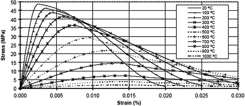
The behavior of concrete is characterized by material property degradation with increased temperature. The stress–strain relationship is defined according to the Euro code 2 (ENV2001) [Citation2] as shown in . Here, the initial elastic behavior is followed by a plastic-hardening curve up to the ultimate stress, after which, a decaying zone represents the post-crushing behavior for concrete. This relationship has the advantage of allowing the definition of a stress level for large plastic deformations, usually reached during fire conditions.
Fig. 1 Concrete stress–strain relationship at high temperature [Citation2].
Many investigators have reported test results on properties of concrete due to elevated temperatures during the last five decades such as
Malhotra [Citation3] who investigated the effect of elevated temperatures on compressive strength of concrete by heating 5 cm × 10 cm cylinders using various mix proportions and water-cement ratios. The test results have been expressed as percentage of unheated strength and plotted against the temperature. Also he noted that E-value of concrete also drastically reduces with temperature.
Effect of high temperature on steel
Like concrete, steel also loses strength with temperature. The magnitude of the loss and the rate of reduction depend upon the type of steel and its manufacturing process. Mild steel and hot-rolled high-tensile steel retain only 50% of its normal temperature (20 °C) yield stress at about 600 °C, but up to a temperature of about 300 °C the strength (yield stress) appears to be slightly higher than at room temperature. For cold-worked high-tensile reinforcement, 50% reduction of the yield stress usually occurs at a temperature around 550 °C. The rise in strength up to a temperature of 300 °C is also less. If reinforcing bars are heated up to 600 °C, they virtually recover their full normal temperature strength when cooled to room temperature again [Citation8].
Effect of high temperature on loaded columns
In 2000 Karamoko et al. [Citation1], studied reinforced concrete columns designed for stability against fire. A Monte Carlo simulation technique is used to assess the probability of failure by taking into account the effect of temperature on statistical distributions. The reliability of columns exposed to fire appears particularly affected by variations in the parameters such as the design exposure time, slenderness, and steel ratios. A possibility of reducing the sensitivity is proposed.
Also Rashad in 2000 [Citation4] evaluated the effect of elevated temperatures on loaded RC columns containing different aggregate types and different mineral admixtures,
Muhammad, in 2002 [Citation5] studied experimentally and analytically the residual vertical and lateral load capacities of short centrically loaded modeled reinforced concrete columns when the modeled columns were fired in an actual fire furnace under different circumstances during and after fire test.
In 2003 Helmi [Citation6], focused on the effect of different protection materials on the structural response of retrofitted RC columns. Also Ibrahim and Marzouq, in 2003 [Citation7], evaluated the effect of the method of fire extinguishing methods on the capacity of reinforced concrete compression members.
Fire protection materials
In 1999 Sakumoto [Citation8], discussed fire-safe design methods incorporating the application of new fire-protection materials. New fire-protection materials targeted in the research are tumescent coating that foams when heated and a fire protection ceiling provided with plaster boards to isolate heating coming from the room.
Experimental investigation
Test specimens
This study includes the investigation of the temperature gradient through the depth of half scale reinforced concrete strengthened columns by CFRP under structural load and sustained elevated temperature 900 °C for 30 min, according to ASTM E119, using different protection coating materials.
The details of the tested columns are shown in which shows all protection materials’ thickness and fire duration of the investigated specimens, and key legends that will be used throughout the whole study. Also, the different types of protection are given. For example “CV” refers to Column protected with vermiculite as a heat barrier. All specimens were protected with 3 cm layer thickness.
Table 1 Half scale column specimen details.
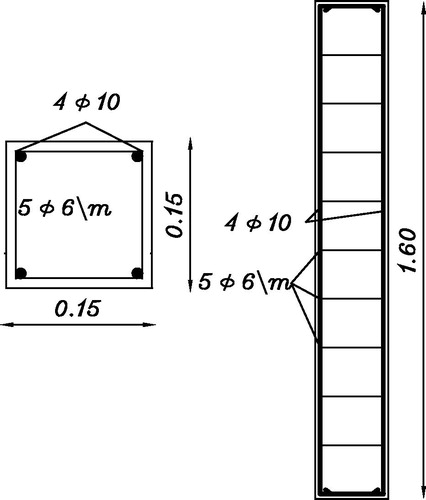
Column element consists of 14 specimens of reinforced concrete columns of 15 × 15 cm cross section, 160 cm length and same steel reinforcement as shown in . Two of these columns were tested without strengthening and without exposure to fire. The remaining columns were strengthened with 30 cm width of CFRP sheets. The method of strengthening is given in section 3-9-3. On the other hand two CFRP strengthened columns of this group were tested without exposure to fire. They are considered as control columns. The remaining of the strengthened column specimens were protected with different types (Ferro-cement, Vermiculite, Feldspar, Quartz, Thermal Brick, Sand Glass, Perlite, Dry A5 and Alumina cement in some mixes) as reported in .
Fig. 2 Half scale Columns’ Reinforcement.
Characteristics of materials used in concrete
The used sand is natural desert sand, the used gravel is natural stone of 10 mm maximum nominal size, and the cement used is Portland cement CEM I 42.5 R. Also tap water is used in mixing concrete. Water cement ratio of 0.42 by weight was used.
Steel reinforcement
For half scale column the longitudinal reinforcement used is high tensile steel bars with a nominal diameter of 10 mm. The lateral reinforcement used, hoops, is plain mild steel with 6 mm nominal diameter. The properties of both longitudinal and lateral steels are listed in .
Table 2 Properties of reinforcement steel bars in columns.
CFRP composites
For half scale column, the sheets were 300 mm width and the total length of rolls were about 50 m. the average thickness of the weave was 1.3 mm. shows that the properties of Sika Carbodur Carbon Fiber sheets according to supplier specifications of Carbon Fiber sheets.
Table 3 Properties of carbon fiber sheets used in columns.
The adhesive material
The adhesive material used in the test program is Sikadur 330. This type consisted of resin “A” and hardener “B” with ratio of 4:1 by weight, respectively according to the provider’s instructions. Setting time for both adhesives is 30 min at 25 °C.
Heat barrier materials
This section gives in detail the description of the used materials as a protection material.
Alumina cement
The cement used in some protection layers is Alumina cement.
Vermiculite
Vermiculite is a 2:1 clay, meaning it has 2 tetrahedral sheets for every one octahedral sheet. It is a limited expansion clay with a medium shrink-swell capacity. Vermiculite has been used in various industries for over 80 years. It is used in the construction, agricultural, horticultural, and industrial markets. Vermiculite is the mineralogical name given to hydrated laminar magnesium–aluminum–iron silicate which resembles mica in appearance.
Feldspar
Feldspar is not a single mineral. It is a group of minerals related to each other in structure and chemical composition. Feldspar minerals are aluminum silicates of potassium, sodium, and calcium. Several rare members contain barium, strontium, ammonia, etc. The Feldspar minerals form similar crystals, and it make up nearly half the earth’s crust. Most Feldspar crystallizes in the monoclinic and triclinic systems. Solid solution series exist between several members.
Perlite
Perlite is a generic term for naturally occurring siliceous rock. The distinguishing feature which sets perlite apart from other volcanic glasses is that when heated to a suitable point in its softening range, it expands from four to twenty times its original volume. This expansion is due to the presence of two to six percent combined water in the crude perlite rock. When quickly heated to above 1600°F (871 °C), the crude rock pops in a manner similar to popcorn as the combined water vaporizes and creates countless tiny bubbles which account for the amazing light weight and other exceptional physical properties of expanded perlite. Expanded perlite can be manufactured to weigh as little as 2 lb per cubic foot.
Thermal Brick
Thermal Brick has been fire tested under ASTM guidelines and passed a 4-h plus fire rating. It achieves the industry’s highest fire insurance safety rating.
Thermal Brick achieves the high performance “R” rating of 24 (ASHRAE Series Parallel) due to a combination of offset and constricted thermal pathways and expanded Polystyrene foam inserts that are highly resistant to heat flow. The higher mass of this wall system stores a large amount of heat that is slowly released facilitating moderate indoor temperature changes. These solid walls also effectively seal out uncomfortable drafts. The economic result is lower monthly operating expense.
Dry A5
Dry A5, premixed product of fire resistant, super-per spirant, damp-proof, thermoacoustic insulation mortar, and particularly effective in the damp-proofing of external and internal walls. Dry A5, mortar is composed of hydraulic binders, volcanic silicon-aluminum lightweight aggregate, synthetic fibers and several additives. It does not contain asbestos.
Dry A5 once hardened, is a very light product and its density does not exceed 450 kg/m3. Dry A5 is applied in a 3 cm thickness on the concrete surface. gives the values of heat barrier thermal conductivity.
Table 4 Thermal conductivity of heat barrier materials.
Mechanical properties of hardened concrete
Tests are carried out on standard concrete cubes – The average value of the concrete grades was 280 kg/cm2. The average value of the Modulus of elasticity of concrete was 198 t/cm2, and the average value of Tensile strength was 25 kg/cm2.
Reinforcement of columns’ element
Column specimens are vertically reinforced with four bars of 10 mm nominal diameter and 155 cm length. It had two hooks with right angle with 10 cm long each. The transversal reinforcement of the column is 6 mm diameter. The spacing of the hoops is about 20 cm. The specimen reinforcement details are shown in .
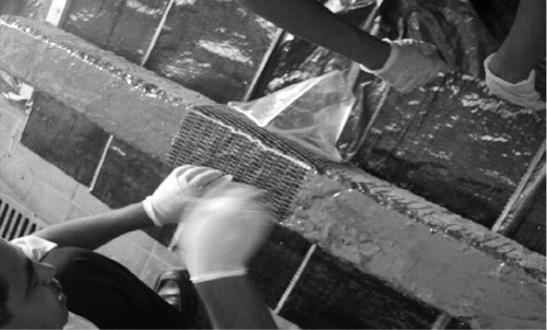
Application of reinforced plastics
For achieving the best possible adhesion between Carbon Fiber Sheet and concrete, the concrete surface was prepared just before the application of adhesive material. The substrate was ground by the shot blasting and the result dust removed by air jet, and then the resin solution and the hardener were mixed together and applied on the specimens using a paint brush. The CFRP is placed on and around the specimens and hidden air is driven away. The thermocouple is positioned in the specimens as shown in .
Fig. 3 Placing Carbon fiber wrapping on columns.
Protection layer mixes
A series of trail mixes, and small scale modified ratio of all protection layers were tested. The best estimation of the trail mixes is shown in , that used in the tested specimens.
Table 5 Mix proportions by weight of protection layers.
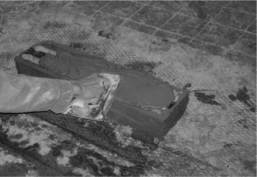
Fire protective coatings’ preparation
Heat barrier layers to protect the CFRP from high temperature are placed on the surface of CFRP layer. Different materials are chosen. Wire mesh is placed in the center of protection material to avoid splitting in the protection layer as shown in .
Fig. 4 Wire mesh in coating layer.
Loading system
Electrical hydraulic jack with 100 ton capacity was used for loading the column specimens. A loading head was connected to the moving arm to minimize the effect of high temperature on the jack.
Thermocouples
Thermocouples used were type K, five thermocouples were connected to the data logger. The first to get mille-volt reading of the temperature inside the furnace, the second to get mille-volt readings between coating and concrete surface and the others to get mille-volt readings through specimen’s cross section at its mid-height as shown in .
Fig. 5 Thermocouple position in column section.

Data acquisition system
A portable machine instrument data Acquisition System (NIDA960) is used in capturing data from thermocouple. The (NIDA960) was adjusted to sample the data from thermocouple at a rate up to 100 readings per second per thermocouple. Because of the long time needed for each specimen in furnace, one reading per second per thermocouple was recorded. This rate enables to read all events of the test with a suitable number of readings which can be easily analyzed.
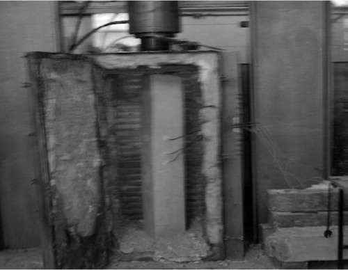
Column test procedure
For half scale column specimens, four control specimens were tested under static load only and room temperature. Two of them were unwrapped and the last were wrapped with two CFRP layers. The other specimens are placed inside the furnace and loaded by the hydraulic jack to the appropriate load level equal to the service load (1/3 of the ultimate failure load). The furnace is then turned on and the temperatures are recorded at interval until it reached the maximum appropriate temperature, then the temperature is maintained constant to the specified duration. After reaching the specified duration, the furnace is turned off and the specimen is left to cool then it is brought out to be tested to failure and recorded its residual capacity as shown in .
Fig. 6 Column test setup.
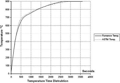
Construction of the furnace
A furnace with some special specifications was built with dimensions of 0.6 × 0.8 and 1.5 m height and the maximum temperature can be reached to 1200 °C. The method of heating inside the furnace was controlled to simulate the ASTM temperature curve as shown in .
Fig. 7 Time–temperature curve of the furnace compared to ASTM.
Experimental results and discussions
Experimental results of specimens were tested. Two of these columns were tested without strengthening and without expositing to fire and the rest were strengthened with 30 cm width CFRP sheets. Columns were subjected directly to 900 °C for 30 min and centric service axial compression load at the same time.
The tests were designed to asses, the validity of using some protection material against fire on the surfaces of reinforced concrete strengthened columns, and to obtain a better insight into the residual mechanical capacity of columns after exposure to 900 °C for a period duration of 30 min. The principal test results are summarized in .
Table 6 Summery of the test result of columns.
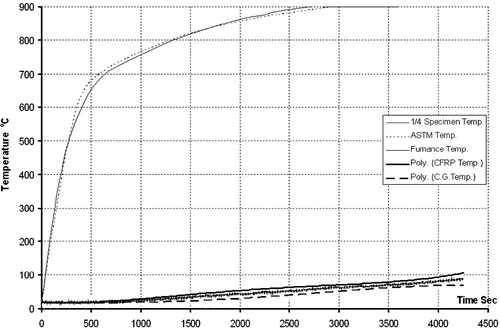
Column (CFC)
In this test, one strengthened column specimen protected by a 3 cm Ferro-cement layer was tested under fire at 900°C of for 30 min (CFC). During the fire test the specimen was subjected to centric service compression load. shows the furnace time–temperature curve compared by ASTM curve temperature at CFRP. The Ferro-cement protection layer reduced CFRP temperature by 93% at 900 °C for a period duration of 30 min and 88.11% at the end of the test, while reduced temperature at ¼ depth of concrete by 94.22% at 900 °C and 90.22% at the end of the test. Temperatures at C.G oc cross section of concrete at mid height of column were reduced by 95.56% at 900°C and 92.22% at the end of the test.
Fig. 8 Time–temperature curve of column protected by ferro-cement (CFC).
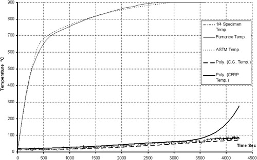
Column (CFCA)
One strengthened column specimen protected by Ferro-cement with alumina cement (CFCA 3 900 30) was tested under fire at 900°C of for 30 min (CFC). shows the furnace time–temperature curve compared by ASTM curve and specimen temperature. The Ferro-cement with Alumina cement protection layer reduced CFRP temperature by 94% at 900 °C. At ¼ concrete section, temperature reduced by 94.88% at 900 °C and 90.67% at the end of the test. Ferro-cement with Alumina cement protection layer reduced temperature at C.G of cross section of concrete at mid height of column by 95.67% at 900 °C and 92.33% at the end of the test. The reduction in the failure load was 9.4% of control specimen the (CS).
Fig. 9 Time–temperature curve of column protected by ferro-cement with alumina cement.
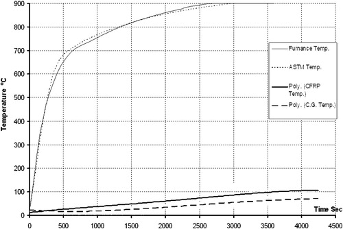
Column (CV)
Using 3 cm thickness of the vermiculite protection material (CV), shows the furnace time–temperature curve compared by ASTM curve at ¼ and ½ concrete cross section at mid height of column. Protection layer of vermiculite reduced the CFRP temperature by 91.89% at 900 °C and 88% at the end of the test. The reduction in the failure load was 21.1% of the control specimen.
Fig. 10 Time–temperature curve of column protected by vermiculite.
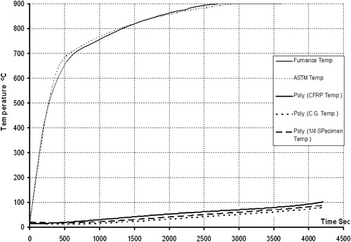
Column (CVA)
One strengthened column specimen and protected with 3 cm thickness of the vermiculite with alumina cement protection material (CVA). show that CFRP temperature was reduced by 93.11% at 900 °C and 88.89% at the end of the test. Temperatures at C.G of concrete section were reduced by 95.33% at 900 °C and 91.22% at the end of the test. The reduction in the failure load was 12.5% for the (CS).
Fig. 11 Time–temperature curve of column protected by vermiculite with alumina cement.
Column (CP)
Column protected with 3 cm thickness of the perlite protection material (CP) which shown in , show temperature curve compared by ASTM curve and cross section temperatures. The perlite protection layer reduced CFRP temperature by 93.33% at 900 °C and 90.22% at the end of the test. The temperatures at concrete cross section at mid height of column were reduced by 95.22% at 900 °C and 91.33% at the end of the test. The reduction in the failure load was 15.62% for the (CS).
Fig. 12 Time–temperature curve of column protected by perlite.
Column (CPA)
When perlite with alumina cement was used as protection material (CPA) it reduced temperatures at ¼ the concrete cross section by 94.67% at 900 °C and 92% at the end of the test. While reduced temperature at C.G of cross section of concrete column at mid height by 95.56% at 900 °C and 93.22% at the end of the test. The reduction in the failure load was 10.8% for the (CS) as shown in .
Fig. 13 Time–temperature curve of column protected by perlite with alumina cement.
Column (CF)
Feldspar protection material (CF) also was tested. shows the result. The Feldspar protection layer reduced CFRP temperature by 91% at 900 °C and 86.44% at the end of the test, while reduced ¼ concrete cross section temperatures by 93.33% at 900°C and 89.67% at the end of the test. The C.G of concrete cross section temperatures were reduced by 94.44% at 900°C and 90.22% at the end of the test. The reduction in the failure load was 21.87% for the (CS).
Fig. 14 Time–temperature curve of column protected by feldspar.
Column (CQ)
Quartz used as protection material (CQ) gives reduction in CFRP temperature by 89.56% at 900 °C and 84.22% at the end of the test, while reduced the ¼ concrete cross section temperatures by 90.22% at 900 Co and 86.44% at the end of the test. The temperatures at C.G of concrete cross section were reduced by 92.22% at 900 °C and 88.67% at the end of the test, as shown in . The reduction in the failure load was 31.25% for the (CS).
Fig. 15 Time–temperature curve of column protected by quartz.
Column (CSG)
Protection by sand glass (CSG) reduced CFRP temperature by 90.78% at 900 °C and 84.44% at the end of the test, while reduced the ¼ concrete cross section temperatures by 92.44% at 900 °C and 87.56% at the end of the test. The reduction in the failure load was 37.5% for the (CS) as shown in .
Fig. 16 Time–Temperature curve of column protected by sand glass.
Column (CTBA)
Protected with thermal brick with alumina cement (CTBA) reduced CFRP temperature by 94.11% at 900 °C and 91.11% at the end of the test, while it reduced the ¼ concrete cross section temperature by 94.44% at 900 °C and 91.56% at the end of the test. The temperature of the C.G of cross section of concrete was reduced by 96.33% at 900 °C and 93.56% at the end of the test. The reduction in the failure load was 25% for the (CS) as shown in .
Fig. 17 Time–Temperature curve of column protected by thermal brick with alumina cement.
Effect Dry A5
Two column specimens are protected by Dry A5. Partial failure on the protection layer surface occurred. The reduction in the failure load was 46.88%.
Summary and discussion of column
The crack appearance, distribution on the surface of the protection layer was depending on, the constituent and proportion of protective material mix, and also the protection layer’s thickness. reveals that, Perlite, vermiculite and Ferro-cement protection material have good resistance to thermal flow. Quartz, thermal brick and Dry A5 protection layer had a complete failure of the protection layer surface. Alumina cement improves the crack propagation of protection layer as shown in –.
Fig. 18 Temperature at CFRP layer for column at 800 °C, 900 °C and at the end of ASTM fire test.
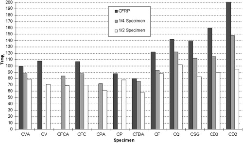
Fig. 21 Reduction in the column failure load compared with the control strengthened and unfired column.
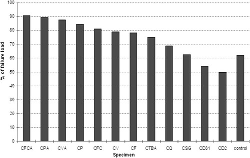
Failure load of protected columns
For all tested specimens the ultimate failure load was less than the ultimate failure load of the control specimen but was higher than the failure load of the un-strengthened unfired column specimen (C) except column specimens protected by DRYA5.
Conclusions
From the investigation of this study, the following conclusions can be drawn: -
| 1. | For columns the exposure of the CFRP layer and the concrete surface to 100 °C for 1 h directly has no effect on the external surface of the specimens and type of failure but the failure load was reduced by 21% compared with the control column. | ||||
| 2. | The thickness of the protection material has a major effect on the reduction of temperature at the CFRP layer. | ||||
| 3. | Ferro cement-with alumina cement coating is the most efficient heat insulator among the examined coatings. Coating thickness of 3 cm is enough to maintain 90.63% of the initial load capacity of the strengthened column after exposure to 900 °C for 30 min while perlite-with alumina cement maintains 87.5% for the same conditions. Although the presented test has been carried out on half scale models it may be expected that similar results will be obtained when applying this coating to full scale columns. | ||||
| 4. | Although increasing the coating thickness will increase the heat insulation, plain coating of more than 3.0 cm thickness will not be able to stay in place without being reinforced with a suitable wire mesh. | ||||
| 5. | CFRP materials can be used in buildings by using appropriate fire insulation for reinforced concrete columns confined. Columns can endure elevated temperatures of fire under strengthened service loads for more than 70 min. | ||||
Conflict of interest
None declared.
Notes
Peer review under responsibility of Housing and Building National Research Center.
References
- S.KaramokoD.M.FredericB.BernardFire safety of reinforced concrete columnsACI-Struct.-J.9742000642647
- Euro code 2, (ENV2001), Design of concrete structures, Part 1–2 Structural Fire Design, 2001.
- H.L.MalhotraDesign of Fire Resistance Structure1982Chapman and HallNew York
- A.M. Rashad, The effect of elevated temperature on loaded RC columns containing different aggregate types and different mineral admixtures, M.Sc. Cairo Univ. 2000.
- U.F.K. Muhammad, Experimental Study for the Residual Load Capacity of Short Modeled Columns Fired in a Fire Furnace, Ph.D. Cairo Univ, 2002.
- A.I.I. Helmi, Fire protection of reinforced concrete columns retrofitted using advanced composite materials. International Colloquium, 2003, E03MAT28.
- H.M.IbrahimM.H.MarzouqEffect of fire extinguishing methods on the capacity of reinforced concrete compression membersPort-Said Eng. Res. J.722003513521
- Y.SakumotoResearch on new fire-protection materials and fire-safe designJ. Struct.-Eng. ASCE.1821999392407