
Abstract
The efficient use of FRP reinforcement in deep members has been hindered due to a lack of knowledge on the behavior of such members. Till now, most of researches have mainly focused on the flexural or shear behavior of shallow members longitudinally reinforced with FRP and most of them used testing at small scales. This paper presents numerical investigation of twelve large-scale concrete deep beams internally reinforced with GFRP bars without web reinforcement failed in shear which were experimentally tested and collected from literature. The collected specimens cover several parameters which usually influenced strength and behavior of deep beams as shear span/depth ratio, the reinforcement ratio, the effective depth, and the concrete strength. Concrete deep beams are generally analyzed using conventional methods such as empirical equations or strut and tie models. These methods however do not take into account the redistribution of forces resulting from non-linear materials’ behaviors. To address this issue, non-linear finite element analysis that incorporates non-linear material behavior as ABAQUS package is used. It was found efficient in handling such analysis; the proposed simulation of the material in the present study is capable of predicting the real behavior of reinforced concrete deep beam reinforced with GFRP bars in terms of load–deflection behavior, failure load, failure mode, crack propagation, GFRP reinforcement strain, and concrete strain distribution, similar to the tested large scale deep beams.
Keywords:
Introduction
Corrosion of steel reinforcement in concrete structures leads to cracking and spalling of concrete, resulting in costly maintenance and repair. An innovative solution to such a problem can be provided by using fiber-reinforced polymer (FRP) as an alternative to steel reinforcement. FRPs are corrosion-free materials and have recently shown a great potential for use in structural applications because of their high strength-to-weight ratio. Therefore, replacing the steel reinforcement with the non-corrosive FRP reinforcement eliminates the potential of corrosion and the associated deterioration. Extensive research programs have been conducted to investigate the flexural and shear behavior of slender (shallow) concrete members reinforced with FRP reinforcement [Citation1]. Very little experimental data and nearly no finite element analysis exist for FRP-reinforced concrete deep beams. So, shear behavior of them has not been sufficiently understood.
The shear capacity of deep beams is a major issue in their design. The behavior of reinforced concrete deep beams is different from that of slender beams because of their relatively larger magnitude of shearing and normal stresses. Unlike slender beams, deep beams transfer shear forces to supports through compressive stresses rather than shear stresses. There are two kinds of cracks that typically develop in deep beams: flexural cracks and diagonal cracks. Diagonal cracks eliminate the inclined principal tensile stresses required for beam action and lead to a redistribution of internal stresses so that the beam acts as a tied arch. The arch action is a function of a/d (shear span/depth) and the concrete compressive strength, in addition to the properties of the longitudinal reinforcement. It is expected that the arch action in FRP reinforced concrete would be as significant as that in steel reinforced concrete and that the shear strength of FRP-reinforced concrete beams having a/d less than 2.5 would be higher than that of beams having a/d of more than 2.5 [Citation2]. The application of the reinforced concrete deep beams within structural engineering practice has risen substantially over the last few decades. More specially, there has been an increased practice of including deep beams in the design of tall buildings, offshore structures, wall tanks and foundations. They differ from shallow beams in that they have a relatively larger depth compared to the span length. As a result the strain distribution across the depth is non-linear and cannot be described in terms of uni-axial stress strain characteristics [Citation3]. Prediction of behavior of deep beams by design codes which contain empirical equations derived from experimental tests has some limitations. They are only suitable for the tests conditions they were derived from, and most importantly, they fail to provide information on serviceability requirements such as structural deformations and cracking. Likewise, the strut and tie model, although based on equilibrium solutions thus providing a safe design, does not take into account the non-linear material behavior and hence also fails to provide information on serviceability requirements. Cracking of concrete and yielding of steel are essential features of the behavior of concrete structures and, therefore, they must be taken into account in predicting their ultimate load capacity as well as service behavior. Failure to do so simply means that the redistribution of stresses in the structure is not taken into account [Citation4]. Thus, the development of an alternative analysis method by FE is needed to understand its behavior. As reported by Enem et al. [Citation4], finite element method (FEM) offers a powerful and general analytical tool for studying the behavior of reinforced concrete deep beams. Finite element method as a tool can provide realistic and satisfactory solutions for linear and nonlinear behavior of deep beam structural elements. Accordingly, it is very needed to generate reliable FE models that can be utilized to enhance the understanding of the fundamental structural response of the FRP-reinforced deep beams and hence optimize its design.
The main objective of this study was to investigate capabilities of the finite element simulation for further study on GFRP-reinforced concrete deep beam behavior instead of conducting expensive time consuming experimental works of large-scale structural elements.
Experimental technique
Characteristics of tested deep beams
Twelve concrete deep beams internally reinforced with GFRP bras were collected from literature [Citation1]. They were constructed and tested to failure. The primary test variables included the a/d, the reinforcement ratio ρ, the effective depth d, and the concrete strength fc′. The objective of the test program was to assess the design parameters that influence the strength and behavior of FRP-reinforced concrete deep beams without web reinforcement. The configuration of the specimens is given in and . The a/d of the specimens were selected to cover a wide range of the deep beam category at the ultimate and equivalent serviceability limit states and to fill gaps in the limited experimental data available on FRP-reinforced concrete deep beams. Specimens were grouped into three series having nominal heights h of 300, 600, and 1000 mm. To study the effect of concrete strength on the shear capacity, both normal- and high-strength concretes were used. The reinforcement in all specimens consisted of GFRP bars, as this is the most commonly used FRP in the industry. The reinforcement ratios were selected such that the stress level in the FRP would not exceed approximately 25% of the specified tensile strength (fFRPu) of the GFRP bar under the equivalent serviceability limit state loads [Citation1]. Note that ACI 440.1R-06 [Citation5] limits the service stress level in the GFRP to 0.20 fFRPu. Overhang lengths were provided beyond the supports in all specimens to allow for anchorage of the FRP reinforcement [Citation1].
Fig. 1 Test setup and specimen geometry.
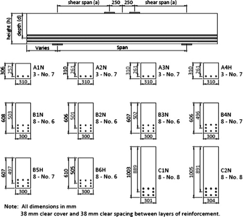
Table 1 Characteristics of GFRP-Reinforced Concrete Deep Beams.
Testing setup
Deep beams were tested in a 6600 kN capacity testing frame under four-point loading as a simple beam. Five linear variable differential transformers (LVDTs) were mounted along the bottom of the specimens to measure vertical deflection at the supports, quarter-spans, and mid-span. Electrical resistance strain gauges were applied to the FRP bars to measure the strain during the test. Each specimen was loaded in five to 10 increments. After each increment, the deflection was held while the crack patterns were photographed. Data from the instrumentation were recorded continuously until specimen failure [Citation1].
Finite element study
The general purpose FE software ABAQUS [Citation6] was employed to generate FE models to simulate numerically the structural response of the previously described concrete deep beams reinforced with GFRP bars. The generated models were validated against all respective experimental results.
Constitutive models
Concrete model
The damaged plasticity model for concrete available in the ABAQUS material library was adopted to model concrete response, since it has been shown to perform satisfactorily in similar applications [Citation7]. The mechanical properties of the used concrete were measured experimentally for all specimens under both compression and tension as shown in .
Table 2 Experimentally Measured Concrete Properties.
GFRP reinforcement
GFRP rebars were simulated as elastic isotropic one dimensional material until failure as recommended by Al-Musallam et al. [Citation8], and the test results of them are tabulated in .
Table 3 Experimental tension test results of the used GFRP bars.
Elements
The ABAQUS element library provides a complete geometric modeling capability. For this reason any combination of elements can be used to make up the model. All elements use numerical integration to allow complete generality in material behavior. Element properties can be defined as general section behaviors, or each cross-section of the element can be integrated numerically, so that nonlinear response can be tracked accurately when needed.
Solid element
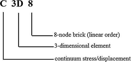
The solid (or continuum) elements in ABAQUS can be used for linear analysis and for complex nonlinear analyses involving contact, plasticity, and large deformations. Regarding the finite element models introduced in this work, three dimensional 8-node first order fully integration continuum elements (C3D8 – Bricks) are used to model the concrete deep beams and loading and bearing plates. The mentioned abbreviation stands for
Truss element
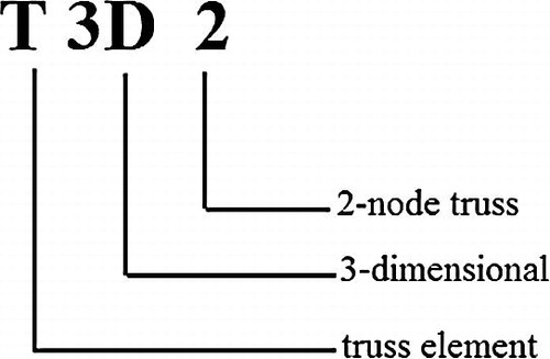
The other basic components in this study are the reinforcing bars for longitudinal reinforcement. The reinforcing bars have mainly the task to transfer normal forces. For that purpose, reinforcing bars modeled as three-dimensional truss elements are sufficient for the purpose. Three dimensional 2-node first order truss elements (T3D2 – Truss) are used to model the reinforcing bars in the FE model of concrete beam specimens. The mentioned abbreviation stands for
Meshing
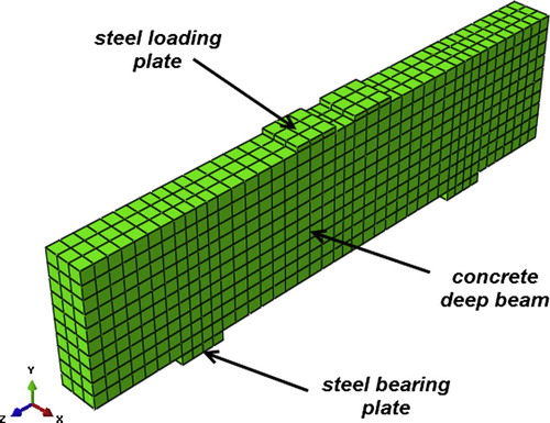
In order to obtain accurate results from the FE model, all the elements in the model were purposely assigned the same mesh size to ensure that each of two different materials shares the same node. The type of mesh selected in the model is structured. The mesh element for modeling of concrete and steel loading and bearing plates is 8-node brick element with three translation degrees of freedom at each node (C3D8). Discrete GFRP rebar can be defined only by truss element which is called T3D2 (3Dimensional-2Node truss element). Andermatt and Lubell [Citation1] reported in their experimental work that the used GFRP bars were coated with sand layer which achieved a higher bond. Consequently, full bond was considered between GFRP bars and surrounding concrete in the FE model. shows the typical mesh of the FE model of deep beam specimens. Modeling and mesh generation are developed using same techniques for all specimens.
Fig. 2 3-D meshing of concrete deep beam model in ABAQUS.
Numerical analysis: verification of FE model
Load–deflection responses
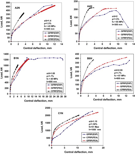
To verify the proposed FE model, a comparison of load–midspan deflection response acquired from test results is demonstrated. The comparison between experimental and the numerical load–deflection curves for the mid span deflection of the deep beams reinforced with GFRP bars is shown in . It shows that the finite element load deflection curves are somewhat stiffer than the experimental plots. After first cracking, the stiffness of the finite element models is again higher than that of the experimental beams. There are several effects that may cause the higher stiffness in the finite element models. The most important is microcracks which are present in the concrete for the experimental deep beams, and could be produced by drying shrinkage in the concrete and/or handling of the deep beams. On the other hand, the finite element models do not include the microcracks. As well known that the microcracks reduce the stiffness of the experimental deep beams, for all specimens, good agreement is in load–deflection relation prior to failure load. For each of the test deep beams, the predicted and the measured maximum loads and deflections were in good agreement. The values given by all specimens were similar to the analytical results; comparative data are summarized in . The mean ratios of experimental-to-numerical ultimate load (predicted by ABAQUS) were 1.01 at a standard deviation of 0.05. Also, finite element analysis gives accurate values of mid-span deflection for deep beams, the average ratios of experimental to predicted deflection at ultimate load equal to 0.98 with standard deviation equal to 0.07. In general, the load–deflection curve from the experiment and the FEM analysis were in very good agreement. This indicates that the constitutive models used for concrete and GFRP bars able to capture the fracture behavior of GFRP-reinforced deep beam accurately. Fig. 3 FE versus experimental load–deflection curves of the studied deep beams.
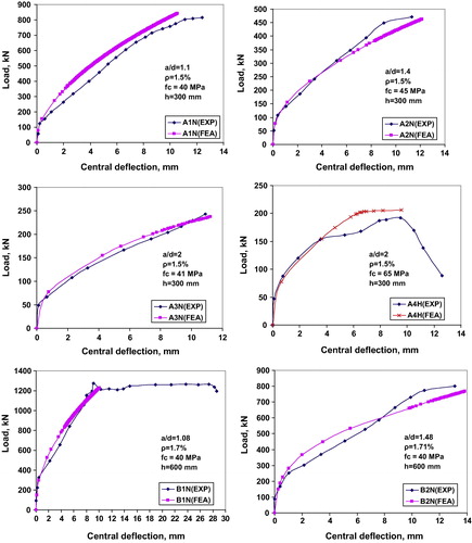
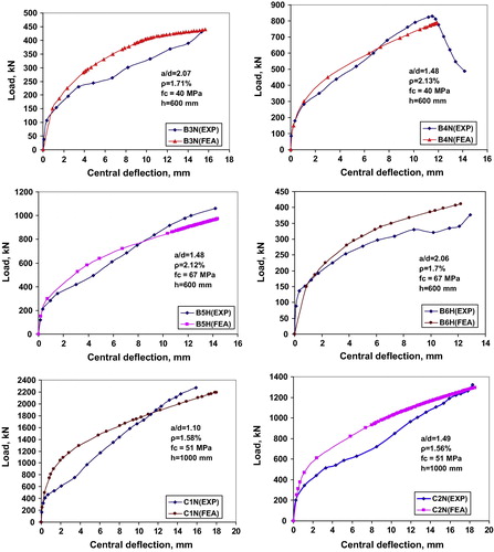
Table 4 Experimental and predicted ultimate load capacity (Pu), deflection at Pu, diagonal cracking load (Pc), and reserve capacity of GFRP-reinforced concrete deep beams.
Diagonal cracking load and reserve capacity
Prior to cracking of the concrete, an elastic stress exists in deep members.
Cracking disrupts the stress distribution and a major reorientation of the internal forces occurs such that forces tend to flow directly from the loading points to the supports. Arch action involves the formation of compression struts to directly transmit the load to the supports while the flexural reinforcement acts as a tie holding the base of the arch together. Unlike slender members with no web reinforcement, deep members have substantial reserve capacity after diagonal cracking as reported by Wight and MacGregor [Citation9]. The diagonal-cracking strength is defined as the strength at which the first fully developed major diagonal tension crack appears in the shear span. The diagonal tension cracking strength was observed to be considerably less than the ultimate strength. Many mechanisms may be responsible for such behavior. However, the major phenomenon is attributed to the arch action mechanism. Deep RC beams exhibited significantly enhanced shear resistance after first diagonal cracking as a result of strong strut action of concrete in compression. The Pc/Pu (diagonal cracking load/ultimate load) ratio serves as a measure of the reserve load capacity after the formation of the first inclined crack. The reserve load capacity was analyzed from the experimental observations and F.E. results for all beams (). The ratio Pc/Pu (reserve capacity) in all deep beams lies in the range between 0.27 and 0.85 from experimental results and the same ratio lies in the range between 0.28 and 0.75 as obtained from F.E. (). Andermatt and Lubell [Citation9] pointed out in their paper that the low or high reserve load capacity was indicative of the formation of arch action after inclined cracking occurred, and this verifies through matching the experimental results with F.E. analysis. The mean ratio of experimental-to-predicted (by ABAQUS) of diagonal cracking load is 0.99 at a standard deviation of 0.05, and mean ratio of experimental-to-predicted reserve capacity is 0.98 at a standard deviation of 0.08 (). On the other hand, as reported by Andermatt and Lubell in their study [Citation10] the strut-and-tie model in Canadian code (CSA A 23.3-04) [Citation11] gives an average ratio of experimental ultimate capacities to predicted ones equal to 0.81, with a standard deviation of 0.16 and the strut-and-tie model in American code (ACI 318-08) [Citation12] and Egyptian code (ECP 203-07) [Citation13] gives the mean of test to predicted values equal to 0.60 with standard deviation of 0.2. This confirms that the finite element analysis attained a higher accuracy for predicting both ultimate load failure and diagonal cracking load than these codes.
Failure mechanisms
contains four types of failure mechanisms that were observed experimentally by Andermatt and Lubell [Citation1]; these types are
| 1. | Diagonal concrete tension failure (DT) or splitting failure: it occurred in specimens A4H and B6H. The diagonal crack formed in each shear span from the inside edge of the reaction plate toward the inside edge of the loading plate. The diagonal crack extended above the diagonal line between the centerlines of the loading and support plates as shown in . | ||||
| 2. | Flexural compression failure (FC): it occurred in specimens A1N and B1N. This type of failure was characterized by the crushing of the concrete in the flexural compression zone between the two loading plates as shown in . | ||||
| 3. | Shear compression failure (SC): it was the most common failure mode, occurring in six of the specimens (). Shear compression failure was characterized by the crushing of the concrete in the flexural compression zone at the tip of the main diagonal crack. The main diagonal crack extended from the inside edge of the support plate toward the inside edge of the loading plate, into the flexural compression zone. In this type of failure, the specimens would fail suddenly with almost no warning and movement would occur along the diagonal crack. shows a typical shear compression failure. | ||||
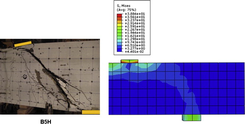
| 4. | Compression strut failure (S): failure of the diagonal compression struts occurred in specimens B5H and C2N. In both specimens, one of the diagonal compression struts would fail in a very brittle and noisy manner. shows the diagonal compression strut failure in specimen B5H. | ||||
Fig. 4 Experimental and finite element pattern of diagonal concrete tension failure (DT) for specimen B6H.
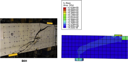
Fig. 5 Experimental and finite element pattern of flexural compression failure (FC) for specimen A1N.
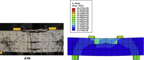
Fig. 6 Experimental and finite element pattern of shear compression failure (SC) for specimen A2N.
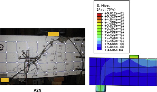
Fig. 7 Experimental and finite element pattern of compression strut failure (S) for specimen B5H.
In cases where the specimen failed in shear-compression (SC), the load decreased abruptly upon reaching the ultimate value and failure was brittle. On the other hand, for specimens that failed in flexure (FC), the load remained almost constant with increasing deflection at ultimate, indicating ductile specimen behavior. In all specimens, the cracks propagated toward the loading point as the load was increased. This was accompanied by more flexural-shear cracks along the specimen shear spans. Specimens that did not fail in flexure also experienced diagonal splitting, which eventually led to a shear-compression failure resulting in the crushing of concrete in the compression zone of deep beams. The failure of specimens was sudden and explosive and most of specimens failed in shear compression as mentioned by Andermatt and Lubell [Citation1]. ABAQUS can monitor and capture the shape and propagation of cracks during loading till failure. The prediction of the failure modes of all the beams by finite element agrees with the experimental observations (–).
GFRP bars reinforcement strains
Importance of showing tensile reinforcement strains, is considered as an indicator of whether and to what extent a tied arch mechanism formed in the specimens. In a fully developed tied arch mechanism, the strain level in the reinforcement is expected to be approximately uniform from support to support for both experimental and FE results as shown in –. Andermatt and Lubell [Citation1] reported in their experimental study that for all specimens, the strain distribution between the supports at peak load was approximately constant indicating an arch mechanism had developed. The experimental strain distribution along the bottom layer of GFRP reinforcement of B1N as the load increased is shown in and the anticipated strains by FE are shown in , both patterns are typical for all specimens. In the majority of the specimens, the strain in the GFRP at the center of the support was significantly lower than the strain whether read (experimentally) or predicted (by FE) at mid-span. The strain readings of the bottom bar increased rapidly in the vicinity of the first crack, usually in the constant moment region (mid-span). As more cracks formed closer to the supports, the measured strains in the GFRP reinforcement would also increase closer to the support. In the un-cracked regions, strain readings showed minimal strain changes in the GFRP. As loading progressed, the strains in the reinforcement became similar between the supports indicating the formation of a tied arch mechanism. The strain level in the bottom reinforcement layer outside of the span of specimen B1N is relatively high at the final failure load of 1273 kN. The splitting crack that had been formed near the location of the bottom reinforcement was caused by increase in the GFRP reinforcement strain level. The strain of longitudinal reinforcement in all specimens did not reach 60% of ultimate tensile strain of GFRP bars () throughout the tests. shows that the F.E. results of generated strain in top layer of GFRP reinforcement are lower than the generated one in bottom layer, and this phenomenon is due to that the bottom GFRP reinforcement anchored a grater amount of force than the upper layers. Consequently, different design codes which incorporated strut and tie method for analysis as Canadian code (CSA A 23.3-04) [Citation11], American code (ACI 318-08) [Citation12], and Egyptian code (ECP 203-07) [Citation13] are not valid for analysis and design of deep beam reinforced with FRP bars, because they are assumed that all layers of reinforcement carry the same tensile stress and so the same strain. However, this is only true when all reinforcement has yielded (as in the case of steel bars), which is not the case with the fully linear elastic material as FRP bars.
Fig. 8 Experimental reinforcement strain distribution along the bottom layer of reinforcement as the load increased for beam B1N [Citation1].
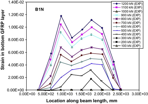
Fig. 9 Predicted reinforcement strain distribution along the bottom layer of reinforcement as the load increased for beam B1N by ABAQUS.
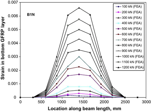
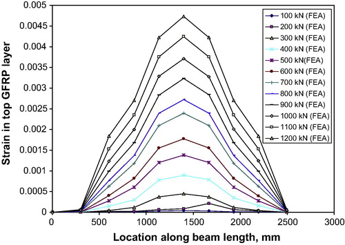
Fig. 10 Predicted reinforcement strain distribution along the top layer of reinforcement as the load increased for beam B1N by ABAQUS.
Concrete strain distribution
Distribution of strains along the concrete surface of beam height at mid-span and compression strut were modeled by finite element analysis using ABAQUS, and the various locations of strain gauges to monitor the strains are shown in . Plots of the strain variations determined by the FE analysis along the section height at the mid length and neutral axis depth variations of all beams under first crack load and ultimate load are shown in . It shows that the strain distribution in GFRP-reinforced concrete deep beams is nonlinear. The number of neutral axis (N.A.) at ultimate load is one, while there are more than one neutral axes before ultimate failure. The number of neutral axes decreases with incremental loads and at ultimate stage only one neutral axis is present. The compression strain in the top fiber of the mid-span section increases as the load increases, but in the tension area, the strain predictions were disturbed by the cracks in this area. As shown in , at the ultimate load state, the compressive strain distribution in the concrete is nonlinear as it no longer follows the parabolic shape or intensity linearity of normal (shallow) beams. This condition is due to the predominant effect of the horizontal bar post-cracking, the reduction in the concrete’s compression area and the shear deformation that is prevalent in deep beams. CSA design code provision [Citation11] states that the maximum compression strain for steel-reinforced deep beam design is 0.002, which is lower than for a normal beam (0.003). Till now, it has no provision for FRP-reinforced deep beams. shows that compression strains of most deep beams range from 0.001 to 0.002 much lower than those of normal beams reinforced with FRP bars which also equal to 0.003 [Citation5] as steel-reinforced shallow beams. This observation should be taken into consideration when designing a deep beam, since the maximum strain at the extreme compression fiber is comparatively small. The difference in the maximum compression strain in the extreme compression fiber in shallow and deep beams is due to reasons such as the size effect and the load transferring mechanism. The other reason was the concrete strength. In a high strength concrete (HSC) beam section, a shallower compressive stress block is required to equilibrate the tension zone forces. Therefore the neutral axis in a HSC beam is closer to the extreme compression fiber compared to an normal concrete strength (NSC) beam with the same reinforcement ratio. The lower neutral axis depth is expected to result in higher plastic strains in the tension reinforcement, leading to ductile behavior. All these aforementioned reasons justify the fact that GFRP-reinforced deep beams exhibit a lower ultimate strain in the extreme compression fiber. Furthermore, since deep beams have more than one neutral axis before the ultimate load, the section design equation for FRP-reinforced normal (shallow) beams is not valid for deep beams. In addition, it is important to consider the nonlinear behavior of GFRP-reinforced deep beams in the strain and stress distribution. GFRP-reinforced deep beams do not conform to Bernoulli’s assumptions for strain and stress distribution. Bernoulli’s hypothesis facilitates the flexural design of reinforced concrete structures by allowing a linear strain distribution. shows that GFRP-reinforced deep beams are far from being linearly elastic when the ultimate load is reached. This nonlinearity of strain distribution is due to the shear deformations that are often less obvious in FRP-reinforced shallow beams, but that are significant in GFRP-reinforced deep beams. Thus the internal stresses and behavior of GFRP-reinforced deep beams cannot be determined using ordinary beam theory. This reiterates that deep beams do not conform to the common hypothesis for shallow beams that plane sections remain plane after bending.
Fig. 11 Simulated locations of strain gauges along the height of deep beam and compression strut by finite element.
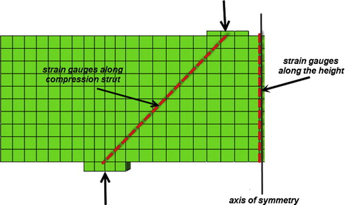
Fig. 12 Concrete strain distributions and neutral axis depth variations along the section height at mid-span of all studied GFRP-reinforced deep beams under first crack load and ultimate load using FE modeling.
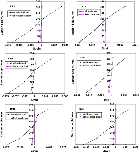
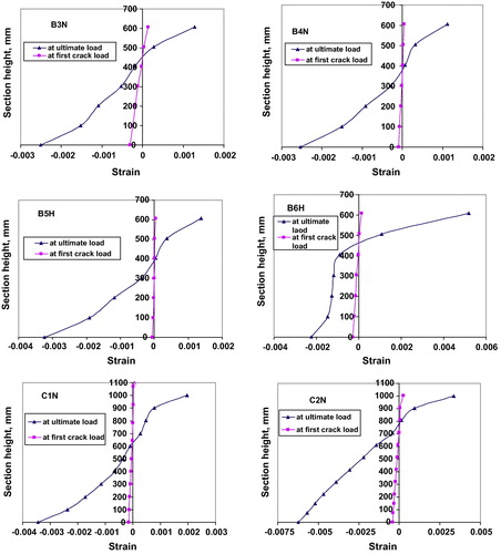
The compressive strains along the strut with the highest measured strain are around 0.0008. This is lower than suggested by the Canadian code (0.002) [Citation11]. As seen in , the maximum compressive strain has occurred around of mid height of these beams and may not occur in the compression strut trajectory line. This has an important implication in the design of GFRP-reinforced deep beams, particularly when using the Canadian code.
Table 5 Maximum compressive strain along mid-span locations and compression strut line.
6- Influence of FRP bar type on behavior of deep beam
This section discusses the difference between behavior of GFRP-reinforced deep beam and CFRP-reinforced deep beam. To achieve this purpose, FE models were constructed by ABAQUS for some selected specimens as A2N, A4H, B1N, B6H, and C1N with replacing GFRP bars by CFRP bars which were modeled as elastic isotropic one dimensional material until failure as recommended by Al-Musallam et al. [Citation8], with a common properties (Ef = 120,000 MPa, ffu = 1600 MPa, and υ = 0.2) as specified by Farghaly and Benmokrane [Citation14]. shows the comparison between results, and it can be seen that deep beams reinforced with GFRP bars exhibit a significant reduction in stiffness after the initiation of the first crack in comparison with the same beam reinforced with CFRP reinforcement. At the ultimate load, the mid-span deflection of GFRP-reinforced deep beams as A2N, A4H, B1N, B6H, and C1N was about 3.5, 2.5, 2.4, 3.6, and 1.7 times more than the CFRP-reinforced ones respectively. This behavior is attributed to the low elastic modulus of the GFRP bars (∼40,000 MPa) compared to that of the CFRP bars (120,000 MPa). The low modulus of elasticity of the GFRP bars affects the ability of these bars to control concrete cracking. This decreases the tension stiffening effect for concrete between cracks leading to a reduced effective moment of inertia and hence large deflections, as was experimentally confirmed by Farghaly and Benmokrane [Citation14].
Fig. 13 Effect of FRP bar type on load–deflection response of deep beams.
Conclusions
In this paper, the nonlinear finite element analysis by ABAQUS was used to predict the behavior and strength of concrete deep beams reinforced with GFRP bars in large scale. The agreement between the numerical simulations and experimental findings demonstrates the overall accuracy and reliability of the analytical models in predicting the response of this new type of structural elements. Based on the results of the numerical simulations and comparisons with experimental data, the following conclusions were reached:
| 1. | The results from the finite element simulation agree very well with the experimental observations, especially with regard to load–deflection response, crack patterns at different load stages, failure modes and mechanisms, GFRP bars strains and concrete strains. All these indicate that the constitutive models used for concrete and GFRP bars by ABAQUS are able to capture the fracture behavior of GFRP-reinforced deep beam accurately. Consequently, this method may be used for the nonlinear analysis and design of such elements very efficiently. | ||||
| 2. | Based on the present research, for the studied cases the experiment results of GFRP-reinforced concrete deep beams and the FEM analysis by ABAQUS were in very good agreement, The mean ratios of experimental-to-predicted values for: ultimate load capacities equal to 1.01 with standard deviation of 0.05, mid-span deflection at ultimate load equal to 0.98 with standard deviation of 0.07, diagonal cracking load equal to 0.99 with standard deviation of 0.05, and reserve capacity equal to 0.98 with standard deviation of 0.08. | ||||
| 3. | The present finite element study which has been verified through the experimental results demonstrated, that the abundant reserve capacity was available after the formation of the main diagonal cracks, indicated that GFRP-reinforced concrete deep beams were able to redistribute the internal forces and develop an arch mechanism. | ||||
| 4. | ABAQUS can monitor and capture the shape and propagation of cracks during loading till failure. The predictions of the failure modes of all the beams by finite element agree well with the experimental observations. | ||||
| 5. | Finite element analysis and experimental results show that, as loading progressed, the strain distribution in the longitudinal GFRP reinforcement became approximately uniform between the supports indicating the formation of a tied arch mechanism. | ||||
| 6. | FE analysis in this research shows that the dependence on the current design codes as ACI 318-08, CSA A 23.3-04 and ECP-203-07 in analysis and design of FRP-reinforced concrete deep beams is not accurate because they assumed that all layers of reinforcement carry the same tensile stress and so the same strain; this is not true in case of FRP reinforcement. However, this is only true when all reinforcement has yielded (as in case of steel bars), which is not the case with the fully linear elastic material as FRP bars. | ||||
| 7. | Concrete strain distribution in GFRP-reinforced concrete deep beams is nonlinear, and they do not conform to Bernoulli’s assumptions for strain and stress distribution. This nonlinearity of strain distribution is due to the shear deformations that are often less obvious in FRP-reinforced shallow beams, but that are significant in GFRP-reinforced deep beams. | ||||
| 8. | The number of neutral axes at ultimate load is one, while there are more than one neutral axes before ultimate failure. The number of neutral axes decreases with incremental loads and at ultimate load stage only one neutral axis is present. | ||||
| 9. | Maximum compression strain in the extreme compression fiber of most GFRP-reinforced deep beams at ultimate stage of loading ranges from 0.001 to 0.002 much lower than those of shallow beams reinforced with FRP bars (0.003). This observation should be taken into consideration when designing a deep beam, since the maximum strain at the extreme compression fiber is comparatively small. | ||||
| 10. | The strains measured along the compression strut were less than the value of 0.002 proposed by the Canadian code, with the highest measured strain reaching about 0.0008. This study shows that the maximum compression strain may not occur in the compression strut trajectory line, and the maximum compressive strain has occurred around of mid height of GFRP-reinforced deep beams. This has an important implication in the design of those beams, particularly when using the Canadian code. | ||||
| 11. | Since, the nonlinear strain distribution dominates the GFRP-reinforced deep members behavior, accordingly, finite element analysis is an appropriate technique for analysis and design of such beams. | ||||
| 12. | Deep beam reinforced with GFRP bars showed different behavior than that of beam reinforced with CFRP bars due to the low elastic modulus of GFRP bars. At ultimate load level, the deflection of the GFRP-reinforced deep concrete beam was in the range of 2–4 times more than the CFRP-reinforced deep beam resulting from the low elastic modulus of the GFRP bars. Thus, the deflection, instead of strength will govern the design for concrete deep beam reinforced with FRP bars. | ||||
| 13. | Future work must include the formulation of a constitutive model for time dependent effects such as concrete creep, shrinkage and fire exposure. Also, experimental testing and finite element analysis of continuous deep beams reinforced with FRP bars must be investigated. | ||||
Conflict of interest
None declared.
Notes
Peer review under responsibility of Housing and Building National Research Center.
References
- M.AndermattA.LubellBehavior of concrete deep beams reinforced with internal fiber-reinforced polymer—experimental studyACI Struct. J.1102013585594
- E.G.NawyReinforced Concrete: A Fundamental Approach2003Prentice HallUpper Saddle River
- S. Islam, A. Khennane, Experimental Verification of Automated Design of Reinforced Concrete Deep Beams. SIMULIA Customer Conference, 2012.
- J.I.EnemJ.C.EzehM.S.W.MbagiorguD.O.OnwukaAnalysis of deep beam using Finite Element MethodInt. J. Appl. Sci. Eng. Res.12012348356
- ACI Committee 440. Guide for the Design and Construction of Structural Concrete Reinforced with FRP Bars. ACI 440.1R-06, American Concrete Institute. Farmington Hills, 2006.
- ABAQUS Standard Version 6.13-4 and ABAQUS standard user’s manual. The Abaqus Software is a product of Dassault Systèmes Simulia Corp., Hibbitt Karlsson & Sorensen Inc., 2014.
- R. Malm. Predicting shear type crack initiation and growth in concrete with non-linear finite element method. PhD thesis, Department of Civil and Architectural engineering, Royal Institute of Technology (KTH) Stockholm, 2009.
- T.Al-MusallamH.El-SanadedyY.Al-SalloumS.Al-SayedExperimental and numerical investigation for the flexural strengthening of RC beams using near-surface mounted steel or GFRP barsConstr. Build. Mater. J.402013145161
- J.K.WightJ.G.MacGregorReinforced Concrete: Mechanics and Designfifth ed.2009Pearson Prentice HallUpper Saddle River, New Jersey
- M.AndermattA.LubellStrength modeling of concrete deep beams reinforced with internal fiber-reinforced polymerACI Struct. J.1102013 595-05
- Canadian Standards Association, Design of concrete structures, A23.3-04, Canadian Standards Association, Mississauga, Ontario, Canada, 2004.
- ACI Committee 318, Building Code Requirements for Structural Concrete and Commentary, ACI 318-08, American Concrete Institute, Farmington Hills, 2008.
- Egyptian Code for Design and Construction of Concrete Structures, ECP 203-07, Housing & Building National Research Centre, 2007.
- A.FarghalyB.BenmokraneShear behavior of FRP-reinforced concrete deep beams without web reinforcementJ. Compos. Constr.172013110