
 ?Mathematical formulae have been encoded as MathML and are displayed in this HTML version using MathJax in order to improve their display. Uncheck the box to turn MathJax off. This feature requires Javascript. Click on a formula to zoom.
Abstract
SiO2 nanolayer coated cubic boron nitride (cBN), cBN(core)/SiO2(shell) powder, was prepared by rotary chemical vapor deposition. The cBN/SiO2 powder was densified by spark plasma sintering at 1873 K for 0.3 ks. The hexagonal boron nitride (hBN) phase was not observed in the cBN–SiO2 composites, indicating that the SiO2 nanolayer depressed the phase transformation from cBN to hBN. The relative density of cBN–SiO2 increased with increasing SiO2 content (). The highest hardness of the cBN–SiO2 composite was 17.5 GPa at
and a load of 0.98 N.
1 Introduction
Cubic boron nitride (cBN) is the second hardest material next to diamond [Citation1,Citation2]. The combination of the high thermal conductivity and hardness renders cBN as a cutting tool material. Diamond easily reacts with iron group metals at higher than 973 K. These metals are soluble in diamond and convert diamond into graphite, which causes micro-cracks by volume change, decreasing the hardness and strength. On the contrary, cBN would not react with iron group metals [Citation3], and thus it is used for machining iron group metals at high cutting speed [Citation4]. Due to its strong B–N covalent bond, cBN is usually consolidated at ultra-high pressure of several GPa, which increases the fabrication cost and limits its applications [Citation5–Citation9].
In our previous work, various cBN-based composites, such as Al2O3–cBN, TiN–cBN and SiO2–cBN, were densified by spark plasma sintering using commercial powder mixture [Citation10–Citation13]. The hardness and fracture toughness of the composites augmented with increasing cBN content up to 30 vol%. For example, the Vickers hardness and fracture toughness of SiO2–20 vol% cBN were 12.5 GPa and 1.5 MPa m1/2, about 2 times as those of the SiO2 body, respectively [Citation13]. In order to hinder the self-contaction of cBN particles and improve the sinterability of cBN-containing composites, SiO2 nanolayer <20 nm in thickness was coated on cBN powder forming cBN(core)/SiO2(shell) structure by using rotary chemical vapor deposition (RCVD) method [Citation14]. The hardness value of the SiO2/cBN composite increased to a high of 14.5 GPa, 2 GPa higher than that using SiO2 and cBN mixture powder. The phase transformation of cBN to hexagonal boron nitride (hBN) was hindered by SiO2 nanolayer. Therefore, the cBN(core)/SiO2(shell) powder is a promising source material for the fabrication of high performance cBN–SiO2 composite. The densification and mechanical properties of the SiO2–cBN composite depended on the structure of cBN(core)/SiO2(shell), i.e., the thickness of SiO2 layer. In order to improve the performance of the cBN–SiO2 composite, the thickness of the SiO2 nanolayer should be optimized.
In the present study, the SiO2 content (SiO2 thickness on cBN powder) in cBN(core)/SiO2(shell) was changed up to 42 wt% by RCVD. The effects of SiO2 content on the densification, phase transformation and hardness of the cBN–SiO2 composites by spark plasma sintering were investigated.
2 Experimental procedure
A precursor of tetraethyl orthosilicate (TEOS) was evaporated at 383 K, and its vapor was carried into the reactor by Ar at a flow rate (Rs,Ar) of 0.83 × 10⁻⁹ m3 s−1. Oxygen was introduced into the reactor at a flow rate of 0.25 × 10⁻⁶ m3 s−1. The reactor containing 4 g of cBN powder (Showadenko, 2–4 μm in diameter) was preheated to 973 K. Four blades were attached to the inner surface of the reactor to keep the cBN powder floating by rotation. The total pressure of the RCVD apparatus was kept at 400 Pa. The details of the RCVD apparatus can be found elsewhere [Citation15,Citation16].
The SiO2 nanolayer was coated on cBN (cBN–SiO2) powder by RCVD, and the cBN(core)/SiO2(shell) powder was prepared. The cBN/SiO2 powder was ball milled for 6 h in ethanol using zirconia balls (3 mm in diameter). After drying at 333 K for 24 h, the milled powder was sieved through the 200 mesh, and was filled into the graphite die of 10 mm in inner diameter. SPS (SPS-210LX, SPS Syntex Inc.) was used to consolidate the cBN/SiO2 powder at 1873 K for 0.3 ks. The heating rate was 1.67 K s−1. The load pressure was 100 MPa. The temperature was measured using an optical pyrometer focused on a hole (ϕ 2 × 5 mm) in the graphite die.
The SiO2 content in the cBN powder treated by RCVD was estimated from the weight change. The phase was examined using X-ray diffraction (XRD; Geigerflex, Rigaku Corp., Tokyo, Japan) with Cu Kα radiation. The microstructures were observed using transmission electron microscopy (TEM; JEM-2000EX, JEOL, Tokyo, Japan) and scanning electron microscopy (SEM, Hitach: S-3100H), respectively. The density was measured using the Archimedes’ method and the relative densities were calculated from the theoretical densities of cBN (3.49 g cm−3) [Citation17] and SiO2 (2.20 g cm−3) [Citation18], and averaged from three values measured for each sample. The Vickers hardness (Hv) was measured using a Vickers microhardness tester in a load between 0.0098 and 19.6 N. The hardness was calculated from Eq. Equation(1)(1)
(1) :
(1)
(1) where P (N) is the applied load and d (m) is the average value of the two diagonal lengths for Vickers indentation. The KIC (MPa m1/2) was calculated from Eq. Equation(2)
(2)
(2) using the half length of the crack (c/m) formed around the corners of indentations The fracture toughness (KIC) was calculated from Eq. Equation(2)
(2)
(2) using the half length of the crack (c) formed around the corners of indentations at the load of 9.8 N [Citation19]:
(2)
(2) where P (N) is the applied load and c (m) is the average half length of cracks.
3 Results and discussion
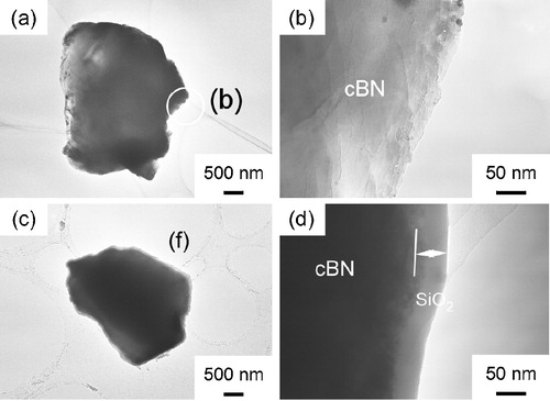
shows the TEM images of cBN (a, b) and SiO2 nanolayer coated cBN at (c, d), 32 wt% (e, f) and 38 wt% (g, h), respectively. The SiO2 nanolayers 50 nm and 100 nm in thickness were uniformly coated on cBN at
and 32 wt% (a–c) and 38 wt% (d–f). At a high SiO2 content of 38 wt%, the thickness ranged from 100 nm to 290 nm. The SiO2 nanolayer easily formed on the surface of cBN at a low concentration of precursor. But when the concentration became higher, the SiO2 nanoparticles could form on the SiO2 nanolayers. Therefore, two apparent SiO2 layers formed on cBN powder surface as shown in (h).
Fig. 1 TEM images of cBN (a and b) and SiO2 nanolayer coated cBN at (c and d), 32 wt% (e and f) and 38 wt% (g and h), respectively.
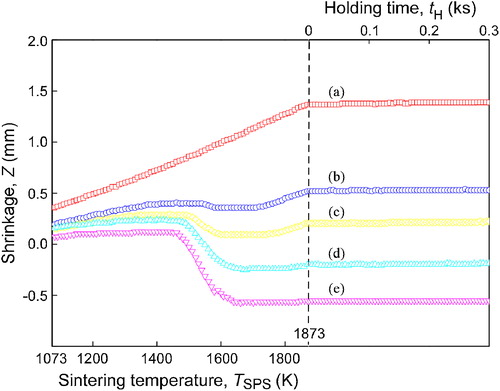
shows the effect of SiO2 content on shrinkage of cBN–SiO2 composites from 1073 to 1873 K and the isothermal shrinkage at 1873 K for 0.3 ks. The shrinkage of cBN was not observed up to 1873 K. The shrinkage of cBN–SiO2 composites stared from 1473 K at . At 1773 K, the shrinkage of cBN–SiO2 composites at
and 15 wt% was small and changed to slight apparent expansion by the thermal expansion again due to the expansion of graphite die. The shrinkage of cBN–SiO2 composite at
ended at 1673 K and kept almost constant till 1873 K, indicating that sintering was completed.
Fig. 2 Shrinkage of cBN (a) and cBN–SiO2 composites at (b), 15 wt% (c), 32 wt% (d), 38 wt% (e) and 42 wt% (f) from 1073 to 1873 K, and the isothermal shrinkage at 1873 K for 0.3 ks.
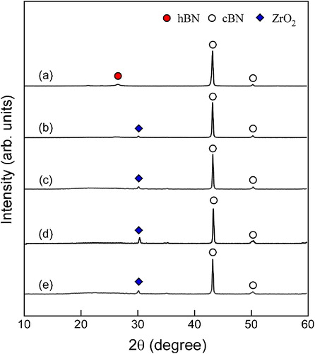
shows the XRD patterns of cBN–SiO2 composites sintered at 1873 K. The hBN peaks were observed in the XRD patterns of original monolithic cBN. No hBN peaks were identified in cBN–SiO2 composites. A small peak of ZrO2 was identified due to the ball milling contamination of the cBN–SiO2 powder. The cBN particles are very hard and will cause the corrosion of ZrO2. In this paper, the cBN content decreased with increasing the SiO2 content, and thus the ZrO2 intensity should decrease correspondingly. On the other hand, the relative density of ZrO2 would increase with increasing the SiO2 content, because the relative amount of cBN decreased correspondingly, where the highest XRD peak is normalized to the cBN peak. Thus the maximum of ZrO2 peak appeared at the certain SiO2 content.
Fig. 3 XRD patterns of cBN (a) and cBN–SiO2 composites at (b), 15 wt% (c), 32 wt% (d) and 38 wt% (e) after sintering at 1873 K for 0.3 ks.
shows the relative density of cBN–SiO2 composites at . The relative density of cBN increased from 73% to 97% with increasing
from 0 wt% to 32 wt%, and then slightly decreased to 96% with further increasing
to 42 wt%. Chen and Yen [Citation20] coated amorphous SiO2 layer on SiC whiskers (SiCw) and Al2O3 powder, and found that the amorphous SiO2 coating improved densification of SiCw-reinforced Al2O3 composites. Since amorphous SiO2 can be sintered by viscous flow at relatively low temperature (∼1573 K), the amorphous SiO2 coated Al2O3 powder was well sintered [Citation21]. In the present study, the almost full densification of cBN may also be attributed to the sinterability of amorphous SiO2 shell due to the viscous flow. The viscous flow of amorphous SiO2 begins at about 1273 K and the outer SiO2 layer wets the substrate and forms a concave neck around the contact point. In order to get a good viscous flow, the SiO2 nanolayer should be thick enough, and thus a proper thickness should be needed. That is why the highest relative density of 97% was obtained at
(the thickness of SiO2 nanolayer is 100–290 nm). The slight decrease to 96% at
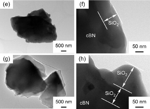
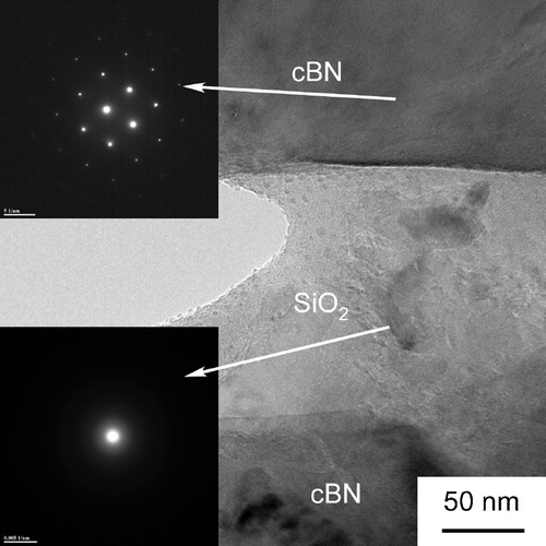
might be due to the agglomeration of the particles. shows the TEM images of cBN–SiO2 composite (38 wt% SiO2) sintered at 1873 K for 5 min. The cBN grains were bonded well by the SiO2 nanolayer. No transformed hBN phase was identified at the cBN/SiO2 surface.
Fig. 4 Effect of on the relative density of cBN–SiO2 composites.
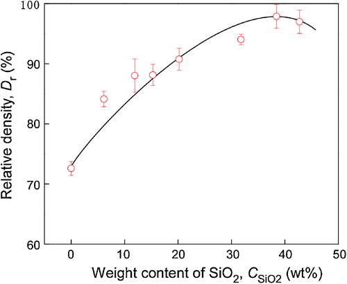
Fig. 5 TEM images of cBN–38 wt% SiO2 composite.
shows the SEM images of SiO2 coated cBN at sintered at 1873 K for 5 min. The white particles were identified to ZrO2 contamination by energy dispersive spectrum (EDS), which should come from the ball milling process. At
and 6 wt%, the SiO2 coated cBN was not well sintered. With increasing
from 15 wt% to 32 wt%, the pores in cBN–SiO2 composite deceased. At
and 42 wt%, the pores almost disappeared. The core(cBN)/shell(SiO2) structure was observed in the SEM images at
, 38 wt% and 42 wt%. With increasing SiO2 content from 38 wt% to 42 wt%, the size of SiO2 shell increased, which was proposed to cause the decrease of hardness in . In the present study, the almost full densification of cBN may also be attributed to the sinterability of amorphous SiO2 shell due to the viscous flow. The viscous flow of amorphous SiO2 begins at about 1273 K and the outer SiO2 layer wets the substrate and forms a concave neck around the contact point. In order to get a good viscous flow, the SiO2 nanolayer should be thick enough, and thus a proper thickness should be needed. That is why the highest relative density of 97% was obtained at
(the thickness of SiO2 nanolayer is 100–290 nm). The slight decrease to 96% at
might be due to the agglomeration of the particles.
Fig. 6 SEM images of cBN (a) and cBN–SiO2 composites at (b), 15 wt% (c), 32 wt% (d), 38 wt% (e) and 42 wt% (f).
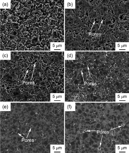
Fig. 7 Effect of content on the hardness and fracture toughness of cBN–SiO2 materials.
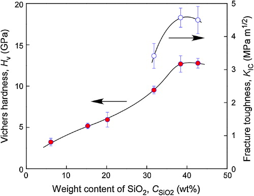
shows the effect of content on the hardness and fracture toughness of cBN–SiO2 composites. The hardness of cBN–SiO2 composites increased from 3.2 to 12.7 GPa with increasing
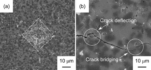
from 0 wt% to 42 wt%. The highest fracture toughness of cBN–SiO2 composites was 4.6 MPa m1/2, about 8 times higher than that of pure SiO2 (0.6 MPa m1/2) [Citation14]. shows the indentation marks of cBN–38 wt% SiO2 composites (a, b). The crack deflection was observed in cBN–38 wt% SiO2 composite. This might have contributed to the high KIC of cBN–38 wt% SiO2.
Fig. 8 Indentation marks of cBN–38 wt% SiO2 composites (a and b).
4 Conclusions
SiO2 nanolayers 6–42 wt% in content () and 14–290 nm in thickness were coated on cBN powder (2–4 μm in diameter) by RCVD at 973 K using TEOS as the precursor. The SiO2 nanolayer enhanced the shrinkage cBN and thus increased the relative density of cBN–SiO2 with increasing
. The highest relative density was 97% at
. The hBN phase was not observed in cBN–SiO2 composites, indicating that SiO2 depressed the phase transformation of cBN. The highest hardness of cBN–SiO2 composites was 17.5 GPa at
and the load of 0.98 N.
Acknowledgements
This study was financially supported by the Japan Society for the Promotion of Science (JSPS), Grant-in-Aids for JSPS fellow, 22-00365, the Rare Metal Substitute Materials Development Project, the New Energy and Industry Technology Development Organization (NEDO), the Global COE Program ‘Materials Integration (International Center of Education and Research), Tohoku University and the 111 Project (B13035).
Notes
Peer review under responsibility of The Ceramic Society of Japan and the Korean Ceramic Society.
References
- R.WentorfR.DeVriesF.BundyScience2081980873880
- P.B.MirkarimiK.F.McCartyD.L.MedlinMater. Sci. Eng. R21199747100
- L.VelG.DemazeauJ.EtourneauMater. Sci. Eng. B-Solid101991149164
- K.BrookesMet. Powder. Rep.6220071417
- H.YoshidaS.KumeJ. Mater. Res.121997585588
- T.TaniguchiM.AkaishiS.YamaokaJ. Mater. Res.141999162169
- X.-Z.RongT.TsurumiO.FukunagaT.YanoDiam. Relat. Mater.112002280286
- Y.J.LiS.C.LiR.LvJ.Q.QinJ.ZhangJ.H.WangF.L.WangZ.L.KouD.W.HeJ. Mater. Res.23200823662372
- R.LvJ.LiuY.LiS.LiZ.KouD.HeDiam. Relat. Mater.17200820622066
- M.HottaT.GotoJ. Ceram. Soc. Jpn.1162008744748
- M.HottaT.GotoJ. Am. Ceram. Soc.92200916841690
- M.HottaT.GotoJ. Ceram. Soc. Jpn.1182010137140
- J.ZhangR.TuT.GotoCeram. Int.382012351356
- J.ZhangR.TuT.GotoCeram. Int.38201249614966
- J.ZhangR.TuT.GotoJ. Alloy. Compd.5022010371375
- J.ZhangR.TuT.GotoJ. Eur. Ceram. Soc.31201120832087
- cBN, JCPDS, International Centre for Diffraction Data, No. 25-1033.
- SiO2, JCPDS, International Centre for Diffraction Data, No. 27-0605.
- B.R.LawnE.R.FullerJ. Mater. Sci.10197520162024
- C.ChenF.YenJ. Mater. Sci.29199432153220
- M.D.SacksN.BozkurtG.W.ScheiffeleJ. Am. Ceram. Soc.74199124282437