
 ?Mathematical formulae have been encoded as MathML and are displayed in this HTML version using MathJax in order to improve their display. Uncheck the box to turn MathJax off. This feature requires Javascript. Click on a formula to zoom.
Abstract
Silicon carbide nanowires (SiCNWs) are a set of promising reinforcement materials due to their superior properties. However, formation mechanism of the SiCNWs synthesized by the thermal evaporation method without metal catalyst is still unclear. To understand the formation mechanism, SiCNWs were synthesized by the thermal evaporation method at 1350 °C using a pre-oxidized Si powder and CH4 gas as precursors. SiCNWs obtained by this method were β-SiC/SiO2 core–shell nanowires with average diameter about 55 nm and with a length up to 1 mm. The exhaust gases during the SiCNWs synthesis process were examined by gas chromatography and the photographs of growth activity of SiCNWs inside the furnace were captured. CO gas was detected during the active formation of SiCNWs. It was clarified that CO gas was one of the byproducts from SiCNWs synthesis process, and the formation reaction of SiCNWs should be 3SiO(g) + 3C(s) → 2SiC(s) + SiO2(s) + CO(g). The formation of SiCNWs was discussed based on the oxide-assisted-growth mechanism.
1 Introduction
Among the various one-dimensional structures based on non-oxide ceramics, silicon carbide nanowires (SiCNWs) have been intensively studied these days due to their very unique properties such as high thermal and chemical stabilities [Citation1], a wide band gap energy and photoluminescence emission peak (2.8 eV and 470 nm, respectively) [Citation2,Citation3]. SiCNWs also show biocompatibility [Citation4]. SiCNWs possess excellent mechanical and thermal properties, such as high bending strength and high Young's modulus over 50 GPa and 600 GPa [Citation5], respectively. Thermal conductivity of SiCNWs is reported to be around 100 W/m K [Citation6]. Many types of SiC such as whiskers [Citation7], platelets [Citation8] and nanoparticles [Citation9,Citation10] were widely used as additives to enhance the mechanical and thermal properties of composite materials. SiCNWs are expected to be used as reinforcement materials for improving the composite's properties further. In our previous research, thermal conductivity of alumina matrix composites was improved by adding a small amount of SiCNWs [Citation11]. Furthermore, SiCNWs have been thought to be suitable for the fabrication of high frequency, high temperature, and high power electronic nanodevices [Citation12–Citation15].
SiCNWs can be prepared by several methods such as chemical vapor deposition [Citation16–Citation18], laser ablation [Citation19] and using carbon nanotubes as a template [Citation20]. These methods require special equipments and complicated procedures that make the production cost very high, and also need some metal catalysts, which reduce the purity and then degrade the crucial properties of SiCNWs. Thermal evaporation method for the synthesis of SiCNWs was developed by Khongwong et al. [Citation21,Citation22]. Silicon powder and methane gas (CH4) were used in this method as sources of Si and C, respectively, while without using any metal catalyst. SiCNWs were synthesized in a tube furnace that is easy to operate, and we get relatively large amount of the products in short time.
The formation mechanism of SiCNWs by thermal evaporation method is needed to be clarified to improve the amount of products and leads to the sufficient SiCNWs for application researches. Recently, many mechanisms have been proposed such as vapor–liquid–solid (VLS) mechanism [Citation23–Citation25], vapor–solid (VS) mechanism [Citation26–Citation28] and oxide-assist-growth mechanism [Citation29–Citation31]. Many chemical equations also have been discussed but there were no mention about experimental results about the exhaust gases from the SiCNWs synthesis by thermal evaporation method and no direct observation of the formation of SiCNWs. From the combination results of these two experiments, we can further understand the formation mechanism of SiCNWs in some points. In this study, we analyzed the exhaust gases from the SiCNWs production system by gas chromatography, and also captured the growth activity of SiCNWs inside the furnace. The synthesis mechanism of SiCNWs by thermal evaporation method was discussed based on the results of the present study and previously reported information.
2 Experimental procedure
2.1 Synthesis and characterization of SiCNWs
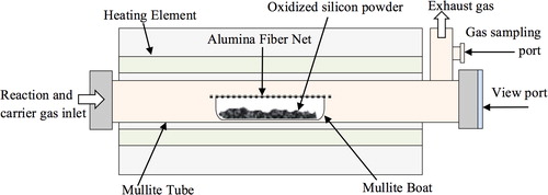
Silicon powder (average particle size 5 μm, 99.99% purity, Kojundo Chemical Laboratory Co., Ltd., Japan) was pre-oxidized in air at 800 °C for 1 h to increase the oxygen content in the raw powder as mentioned in the previous research [Citation22]. Oxidized silicon powder was placed in a mullite boat which was covered with an alumina fiber net (3025-T Standard Woven Fabric, Nitivy Co., Ltd., Japan), and was carefully put in the center of a mullite tube furnace as schematically shown in . The furnace was first vacuumed to the pressure lower than 1.4 Pa at room temperature, and then argon gas (99.9995%) was fed at the rate of 600 cm3/min. After that the furnace was heated up to 1350 °C and soaked for 1 h. By the time of soaking, H2 gas (99.999%) was first fed at the rate of 20 cm3/min for 2 min before the flowing of CH4 gas (99.99%) at the rate of 10 cm3/min. Soaking time was counted from the inlet of H2 gas. After passing for 30 min from the start of CH4 inlet, feeding of H2 and CH4 gases was stopped and the furnace was continuously heated at the soaking temperature for another 30 min. Then the furnace was naturally cooled down to room temperature.
Fig. 1 Schematic illustration of a furnace setup for SiCNWs synthesis.
White-blue wool-like SiCNWs, those formed in the space between the silicon powder and the alumina fiber net, were carefully removed and characterized by scanning electron microscopy (FE-SEM, field-emission type, S-4800, Hitachi, Japan) and X-ray diffractrometry (XRD; Cu Kα, PW 1700, Philips, Holland).
2.2 Observation of growth activity of SiCNWs
For the observation of growth activity of SiCNWs, first a special mullite boat was prepared by cutting across at the end of the boat. Second, we changed the furnace cover at the end of the tube from a stainless steel type to a transparent SiO2 glass. Finally, we set a digital camera at the end of the furnace. Same fabrication procedure was carried out as mentioned above. During soaking, growth activity photographs of SiCNWs inside the tube furnace were captured with a digital camera (12.9 M pixels per frame, D5000, Nikon, Japan), at every one-minute interval time. The exposure time of the images was fixed at a certain value for observation of the change in brightness inside the furnace.
2.3 Gas analysis of SiCNWs synthesis
In this experiment, a gas chromatograph (G-3000, Hitachi Ltd., Japan) equipped with a thermal conductivity detector (TCD) and an active carbon support column (Cat. No. 1001-13006, SUS column material, 2 m length, GL Science Inc.) was used to determine the types and amount of exhaust gases. This equipment setting of the TCD and the active carbon column were able to detect hydrogen (H2), methane (CH4), carbon monoxide (CO), carbon dioxide (CO2) and argon (Ar) gases. For the analysis of CO gas, we changed the carrier gas of SiCNWs synthesis from argon to helium gas (99.99995%), due to the overlapping of the argon and the CO peak in the result. The same heating schedule and the gas flow rates for SiCNWs synthesis were used as mentioned in Section 2.1. During the soaking period of SiCNWs synthesis, 1 cm3 of exhaust gas was sampled by using a microsyringe from the end of the tube furnace and analyzed each gas content by gas chromatography, using helium as a carrier gas with the flow rate of 20 cm3/min. Temperature of the injection port and the detector of the gas chromatograph were set at 100 °C and 50 °C, respectively. The initial column temperature was set at 100 °C throughout the process and analyzing time was set to 10 min. The amount of each gas was calculated from the output peak area, using the calibration curves prepared using standard gases. For comparison, the same set of experiment without putting silicon powder into the boat was conducted for reference.
3 Results and discussion
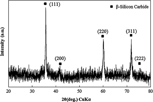
After the synthesizing process mentioned above, a white-blue wool-like SiCNWs product was obtained inside the mullite boat between Si powder and the alumina fiber net. shows an SEM micrograph of SiCNWs synthesized by the thermal evaporation method. SiCNWs obtained by this process had a smooth surface with an estimated length up to 1 mm. The XRD pattern of SiCNWs is shown in , and five diffraction peaks could be identified as (1 1 1), (2 0 0), (2 2 0), (3 1 1) and (2 2 2) reflections of β-SiC without any other impurities. From the transmission electron microscope (TEM) observation, and Fourier-transform infrared spectroscopy (FT-IR) characterizations in our previous work [Citation22], it was confirmed that the SiCNWs produced by this process were core–shell type nanowires those had a single crystal β-SiC core and low-crystalline SiO2 shell.
Fig. 2 SEM micrograph of SiCNWs.
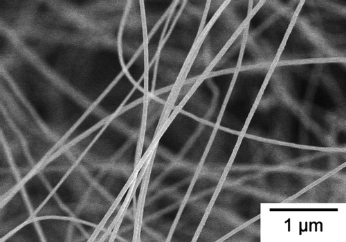
Fig. 3 X-ray diffraction pattern of SiCNWs obtained from this experiment.
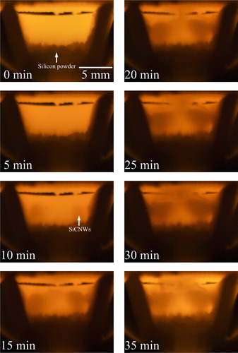
The cross-section photographs of growth activities during SiCNWs synthesis, taken every 1 min from the starting of the soaking time at 1350 °C, are shown in . The first photograph at the starting of soaking time (0 min) was a reference. The black U shape was the cross-section of the mullite boat which was cut at the end of one side, the bright part in the center was another end of the boat, the bright part at the top was the alumina fiber net and the gray part at the bottom was the silicon powder. After about 5 min from the start of H2 gas inlet, the area inside the mullite boat suddenly became dark, which may perhaps be due to the decomposition of CH4 gas to C and H2. Carbon particles should be flowing throughout the tube furnace. At around 10 min, a light gray colored matter appeared at the bottom left and right inside of the mullite boat, and subsequently they were considered to be SiCNWs. At around 15 min, SiCNWs rapidly grew from bottom's left and right sides, and were connected together at the center of the mullite boat. The darker color means slightly lower temperature or the growth of SiCNWs disturbed the light from the end of the boat. At around 20 min, top part of SiCNWs reached the alumina fiber net and continued to grow until the supply of CH4 and H2 gases was stopped at the end of 30 min supply period. By observing the increase of the darker portions inside the boat at every minute, the fastest increase of the darker portions corresponding to the fastest growth rate of SiCNWs was observed to be during 10–20 min or in the middle of CH4 and H2 gas-supply duration. At 35 min (5 min after stopping CH4 and H2 gas-supply), the amount of darker portion did not increase further and the image inside the furnace changed brighter due to the absence of carbon particles in the system.
Fig. 4 Photographs of SiCNWs growth activities every 5 min during the soaking period at 1350 °C.
From the results of gas chromatography at 1350 °C, both CH4 and CO2 gases were not found both in the reference condition (no Si powder in the system) and the system containing oxidized Si powder due to the complete decomposition of CH4 gas, and no generation of CO2 gas in the system was confirmed. shows the amount of CO gas and H2 gas in 1 cm3 of exhaust gases during soaking time at 1350 °C, comparing between the normal production process that contain 0.4 g of the pre-oxidized silicon powder and without silicon powder in the system. The amount of H2 gas and tendency were almost same between both systems. At the first 2 min of the soaking period only H2 gas was supplied into the system, so the amount of H2 gas was increased after CH4 gas was introduced into the furnace and decomposed into C and H2.
Fig. 5 Amount of CO gas and H2 gas in 1 cm3 of the exhaust gas during soaking period of SiCNWs synthesis process.
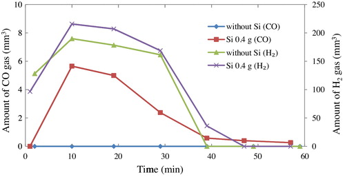
CO gas was detected only in the system containing Si powder and only during formation of SiCNWs. The CO gas was not found after CH4 gas was stopped during the soaking time. It was clarified that CO gas was produced as a by-product during the formation of SiCNWs. The whole growth process can be described as follows,(1)
(1)
(2)
(2)
(3)
(3)
Reaction Equation(1)(1)
(1) shows the generation of SiO gas in the system. Gaseous Si evaporated from solid silicon powder (Si) and reacts with amorphous silica (SiO2) layer on its surface that was produced during pre-oxidation at 800 °C in air before the main experiments. It was confirmed by Khongwong et al. [Citation22] that oxygen content in the silicon raw powder played an important role for SiO generation. The more oxygen content means higher amount of SiO2 on the surface of Si powder, leads to larger amount of SiO gas generation, and then higher amount of SiCNWs could be obtained. The oxygen content in the silicon powder after pre-oxidized at 800 °C was measured to be 4.5% by mass. The vapor pressure of Si at 1350 °C obtained by calculation from JANAF table and experimental by Gulbransen et al. [Citation32] is about 2.48 × 10⁻² Pa. Additionally, the vapor pressure of SiO obtained by the reaction of Si and SiO2 at 1350 °C is about 100 Pa [Citation33,Citation34]. The vapor pressure of SiO was much higher than that of Si so the main gas in the system also confirmed to be SiO gas. shows the SEM micrograph of silicon powder surface just after the beginning of SiCNWs synthesis process. Several parts of surface oxide layer were swelled and tops of bubbles were burst as indicated by arrows. It indicated that Si gas was released from the oxidized Si particles. Reaction Equation(2)
(2)
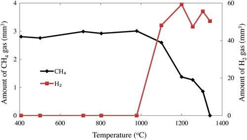
(2) shows the decomposition of methane gas (CH4) into carbon (C) and hydrogen (H2). This reaction was confirmed by sampling the exhaust gas from the furnace, which was heated to high temperature and flowing only CH4 gas in an inert atmosphere, then analyzed by gas chromatography. Some amount of CH4 gas was starting to decompose into C and H2 above 1000 °C and all the CH4 gas was completely decomposed at 1350 °C (only H2 gas were detected), as shown in . Moreover, from the photo-observation at the reaction temperature of 1350 °C, it was observed that the images inside the tube furnace got darken only during CH4 gas supply into the furnace. It should support the presence of carbon particles that float densely in the system.
Fig. 6 SEM micrograph of surface of Si powder just after the beginning of SiCNWs synthesis.
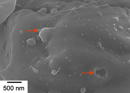
Fig. 7 Amount of CH4 gas and H2 gas in 1 cm3 of the exhaust gas during heating without silicon powder.
Various temperatures were applied for the SiCNWs synthesis. At the lower synthesis temperature around 1300 °C, the generation of SiO gas was very low and also CH4 gas was not completely decomposed, which led to very low formation of SiCNWs. On the other hand, at higher temperature around 1400 °C, large amount of Si was evaporated because the temperature is too close to the melting point of Si (1414 °C), then consumed SiO2 and generated SiO gas at the very beginning of soaking time so there was not enough reaction time for SiCNWs to be formed. As a result, optimum temperature for synthesis of SiCNWs by the thermal evaporation method was around 1350 °C. At this temperature the generation rate of SiO gas and the formation rate of SiCNWs were corresponded to each other's, favorable to the formation of SiCNWs.
From the result of SEM observation, SiCNWs obtained by this method have no metal liquid cap at the tip of nanowires so the formation mechanism was not VLS mechanism. Furthermore, in this study no metal catalyst was added in the system. Thus it is reasonable that the VLS mechanism is not applied in the growth mechanism of SiCNWs in this study. The growth mechanism is suggested to be oxide-assisted-growth mechanism [Citation30,Citation35].
At the soaking temperature (1350 °C) gaseous Si is evaporated from the surface of Si powder, and reacted with SiO2 on the surface of the powder, which then generates SiO gas constantly. In this temperature the decomposition of CH4 proceeds completely, and then carbon nanoparticles are deposited randomly over raw powder, inside and outside surfaces of the mullite boat, the alumina fiber net and also throughout the inner part of the mullite tube furnace. Some carbon nanoparticles react with SiO gas, and form SiC nanoparticles on the surface of not only silicon powder but also any parts of inside the mullite boat, then grew to become SiCNWs with SiO2 amorphous layer and generated CO gas, as shown in reaction Equation(3)(3)
(3) and . SiCNWs those deposited on the surface of the silicon powder grew preferentially due to higher concentration of SiO gas.
The direction of SiC nuclei on the surface of the Si powders should be random, and growth direction of nuclei is also random. After some period the growth of SiC along the [1 1 1] direction may be dominant, since the surface energy of {1 1 1} of SiC is the lowest due to the close pack of this surface in zincblende materials [Citation36]. Stacking faults were easily formed over the {1 1 1} planes in order to decrease the formation energy of SiC [Citation37]. Presence of stacking faults in SiCNWs was previously confirmed by Khongwong et al. [Citation22] through TEM observation. Once nanowires are started to grow, it may rapidly extend along the low formation energy planes or [1 1 1] direction in free space with high concentration of SiO gas and sufficient amount of very tiny carbon particles. Carbon particles are continuously supplied from carrier gas, and deposited on the top of the wires, where reaction Equation(3)(3)
(3) is actively progressing. Observing the inside of the furnace as shown in , a very rapid growth of nanowires was observed just after the “darkening of inside tube” from near the bottom of the boat, where the raw oxidized Si powder was placed. Concentration of SiO gas should be high near the bottom of the boat. It is not sure that such a high growth rate of SiCNWs is attained by the gas–solid reaction mentioned in reaction Equation(3)
(3)
(3) ; however, the size of solid carbon should be small clusters consisted from few tens of atoms for each, it may be possible. The size of carbon clusters should be very small, since they are just after the decomposition of CH4 molecules.
According to reaction Equation(3)(3)
(3) , SiO2 is simultaneously formed with SiC. The amorphous SiO2 layer on the [1 1 1] direction of the nanowires should be unstable due to the large amount of carbon atoms inside it, and it became a kind of molten tip of SiCNWs pre-forming which had the highest energy due to the smallest dimension [Citation38]. Amorphous SiO2 layer on the lateral direction become more stable due to their larger dimension and very smooth surface. SiO gas and carbon clusters were continued to deposit only at the tip of SiCNWs and continued to grow in one dimensional wire shape.
Further confirmation of reaction Equation(3)(3)
(3) was obtained from the diameter of SiC core and thickness of SiO2 shell. The average core diameter of 45 nm and average shell thickness of 10 nm were carefully measured from TEM photographs of more than 50 nanowires prepared by this procedure. If the cross section of each nanowire is circle, the volume ratio of SiC and SiO2 of the nanowire was calculated as 5:11 from the each area. On the other hand, molar volume of β-SiC and amorphous silica are 12.5 cm3/mole and 59.5 cm3/mole, and if the production rate of SiC:SiO2 is 2:1 according to reaction Equation(3)
(3)
(3) , volume ratio of SiC to SiO2 is obtained as 5:12, which is close to the observed volume ratio (5:11).
The alumina fiber net that covered on the top of the mullite boat helped to maintain the reaction zone to be only inside the mullite boat by keeping the SiO gas inside the boat which increase the concentration of SiO gas and let the carbon particles to pass through the boat at right amount.
4 Summary
In summary, β-SiC/SiO2 core–shell nanowires have been synthesized by the thermal evaporation method. Large amount of long nanowires with smooth-surface were obtained and their average diameters were 55 nm and up to 1 mm long. These nanowires had a single crystal β-SiC core growing along the [1 1 1] direction and amorphous SiO2 shell. During the formation of SiCNWs in this process, exhaust gases were analyzed by gas chromatography and the growth activity of SiCNWs was captured by the digital camera. CO gas was detected from the exhaust gases of the production system only when SiCNWs were quickly growing. From these experimental results it was confirmed that CO gas was one of the main byproducts of the SiCNWs formation. The formation reaction of SiCNWs should be:The SiCNWs formation was discussed by oxide-assisted-growth mechanism. According to this reaction, SiO2 is simultaneously formed with SiC. The amorphous SiO2 layer on the [1 1 1] direction should not be stable due to the large amount of carbon atoms inside it and it became a kind of molten tip of SiCNWs pre-forming which had the highest energy due to the smallest dimension. Amorphous SiO2 layer on the lateral direction becomes more stable due to its larger dimension and very smooth surface. SiO gas and carbon clusters were continued to deposit only at the tip of SiCNWs and continued to grow to be one dimensional wire shape.
Notes
Peer review under responsibility of The Ceramic Society of Japan and the Korean Ceramic Society.
References
- D.W.KimY.J.ChoiK.J.ChoiJ.G.ParkJ.H.ParkS.M.PimenovV.D.FrolovN.P.AbanshinB.I.GorfinkelN.M.RossukanyiA.I.RukovishnikovNanotechnology192008225706
- S.-C.ChiuY.-Y.LiJ. Cryst. Growth311200910361041
- J.ChenW.TangL.XinQ.ShiAppl. Phys. A1022010213217
- R.YakimovaR.M.PetoralG.R.YazdiC.VahlbergA.Lloyd SpetzK.UvdalJ. Phys. D: Appl. Phys.40200764356442
- E.W.WongP.E.SheehanC.M.LieberScience277199719711975
- Y.ItoK.TakahashiM.FujiiX.ZhangHeat Transfer-Asian Res.382009297312
- M.I.K.CollinD.J.RowcliffeJ. Am. Ceram. Soc.84200113341340
- Y.ChouD.GreenJ. Eur. Ceram. Soc.141994303311
- H.WangL.GaoJ.GuoCeram. Int.262000391396
- D.ScitiJ.VicensA.BellosiJ. Mater. Sci.37200237473758
- N.JiraborvornpongsaM.ImaiK.YoshidaT.YanoJ. Mater. Sci.48201370227027
- C.O.JangT.H.KimS.Y.LeeD.J.KimS.K.LeeNanotechnology192008345203
- H.-K.SeongH.-J.ChoiS.-K.LeeJ.-I.LeeD.-J.ChoiAppl. Phys. Lett.8520041256
- N.G.WrightA.B.HorsfallJ. Phys. D: Appl. Phys.4020076345
- S.M.PimenovV.D.FrolovA.V.KudryashovM.M.LamanovN.P.AbanshinB.I.GorfinkelD.W.KimY.J.ChoiJ.H.ParkJ.G.ParkDiam. Relat. Mater.172008758763
- L.LinNanoscale3201115821591
- J.WeiK.LiJ.ChenH.YuanJ. Cryst. Growth3352011160164
- B.C.KangS.B.LeeJ.H.BooJ. Vac. Sci. Technol. B2320051722
- S.WenshengZ.YufengP.HongyingW.NingL.Chun SingL.Shuit-TongJ. Am. Ceram. Soc.83200032283230
- Z.PanH.L.LaiF.C.K.AuX.DuanW.ZhouW.ShiN.WangC.S.LeeN.B.WongS.T.LeeS.XieAdv. Mater.12200011861190
- W.KhongwongM.ImaiK.YoshidaT.YanoJ. Ceram. Soc. Jpn.1172009194197
- W.KhongwongM.ImaiK.YoshidaT.YanoJ. Ceram. Soc. Jpn.1172009439444
- C.H.LiangG.W.MengL.D.ZhangY.C.WuZ.CuiChem. Phys. Lett.3292000323328
- H.-J.ChoiH.-K.SeongJ.-C.LeeY.-M.SungJ. Cryst. Growth2692004472478
- X.M.YaoS.H.TanZ.R.HuangS.M.DongD.L.JiangCeram. Int.332007901904
- Y.J.ZhangN.L.WangS.P.GaoR.R.HeS.MiaoJ.LiuJ.ZhuX.ZhangChem. Mater.14200235643568
- J.J.ChenQ.ShiL.P.XinY.LiuR.J.LiuX.Y.ZhuJ. Alloys Compd.509201168446847
- K.ChenZ.HuangJ.HuangM.FangY.-g.LiuH.JiL.YinCeram. Int.39201319571962
- Y.F.ZhangF.L.WangL.Y.ZhangNanoscale Res. Lett.42009153156
- Y.YaoS.T.LeeF.H.LiChem. Phys. Lett.3812003628633
- M.S.Al-RuqeishiR.M.NorY.M.AminK.Al-AzriJ. Alloys Compd.4972010272277
- E.A.GulbransenK.F.AndrewF.A.BrassartJ. Electrochem. Soc.1131966834837
- J.A.NuthIIIF.T.FergusonAstrophys. J.649200611781183
- F.T.FergusonJ.A.NuthJ. Chem. Eng. Data572012721728
- W.M.ZhouZ.X.YangF.ZhuY.F.ZhangPhysica E312006912
- C.LongS.A.UstinW.HoJ. Appl. Phys.8619992509
- W.SeoK.KoumotoJ. Am. Ceram. Soc.79199617771782
- S.Noor MohammadJ. Vac. Sci. Technol. B2620081993