
 ?Mathematical formulae have been encoded as MathML and are displayed in this HTML version using MathJax in order to improve their display. Uncheck the box to turn MathJax off. This feature requires Javascript. Click on a formula to zoom.
Abstract
A ZrC–SiC matrix was fabricated by means of in situ reaction method, using zirconium salt, silicon powder and phenolic resin as raw materials. The performances of zirconium salt determined the possibility of ZrC–SiC matrix fabricated using them. The reactions were completed at a relatively low temperature (∼1500 °C). With this concept to produce a ZrC–SiC matrix costs can be reduced. Three-dimensional needle Cf/ZrC–SiC composites were successfully fabricated via the polymer infiltration and pyrolysis (PIP) process using zirconium salt, silicon powder and phenolic resin as raw materials.
1 Introduction
As hypersonic aerospace vehicles and advanced reusable atmospheric re-entry vehicle developed, carbon fiber reinforced ultrahigh-temperature ceramics (Cf/UHTCs) matrix composites emerge as the application is required, because carbon fiber reinforced silicon carbide matrix composites can no longer withstand ablation environment with high heat flux and pressure gas flows [Citation1]. Cf/UHTCs matrix composites were fabricated through the introduction of UHTCs (such as zirconium carbide, ZrC) into the matrix via various methods, such as chemical vapor infiltration (CVI) combined with modified polymer infiltration pyrolysis (PIP) [Citation2], a soft-solution approach using inorganic precursors [Citation3], hot-pressing and polymer infiltration pyrolysis (PIP) [Citation4], as well as mold-pressing and polymer infiltration and pyrolysis (PIP) [Citation5]. In our previous studies, Cf/UHTCs matrix composites were prepared via polymer infiltration and pyrolysis [Citation1], a liquid precursor conversion method with PIP [Citation6], the vapor silicon infiltration process [Citation7] and in situ reaction [Citation8]. Their micro-structural features, mechanical properties and anti-oxidation and anti-ablation properties were reported in detail.
ZrC is one of the most promising ceramics for ultrahigh-temperature applications due to its exceptional properties and the ability to form refractory oxide scales at high temperatures. However, some studies have obvious disadvantages. ZrC particles cannot be homogenously dispersed in the intra-bundle of composites. Though the distribution uniformity and low fraction problem of UHTC phases can be solved using ZrC precursor, ZrC precursor and commercially available ZrC powders are expensive. At the same time, the raw materials are also costly when Cf/UHTCs matrix composites were produced via in situ reaction. In order to reduce preparation costs, zirconium salt with low cost would be used to fabricate Cf/UHTCs matrix composites. Zirconium salt includes zirconium carbonate (3ZrO2·CO2·H2O), and so on. In this method, zirconium source, carbon source and silicon source are provided by zirconium salt, thermosetting phenolic resin and silicon powder besides ZrSiO4, respectively.
In situ reaction of ceramic composites is an attractive and effective way to obtain advanced materials. Recently, nonoxide-boron nitride composites and boride-containing ceramics composites have been fabricated via in situ synthesis [Citation9–Citation11]. The obtained materials have excellent properties such as homogeneous microstructures, higher chemical stability and better physical mechanical properties than the conventionally processed ones [Citation10]. In view of this, Cf/UHTCs matrix composites are fabricated via in situ reaction.
So the purpose of this work is how to synthesize simply and rapidly a ZrC–SiC matrix via in situ reaction using zirconium carbonate or zirconium sulfate, Si powders and thermosetting phenolic resin as raw materials. The mixture of ZrC and SiC via pyrolysis of a mixture of ZrO2 (or carbonate), Si powder and a phenolic resin was fabricated successfully. Meanwhile, the ZrC–SiC matrix obtained compare with the ZrC–SiC matrix in our previous studies. Finally, 3D Cf/ZrC–SiC composites were successfully fabricated using zirconium salt, silicon powder and phenolic resin as raw materials.
2 Experimental procedure
2.1 ZrC–SiC matrix fabrication
Zirconium carbonate (<2 μm, >98 wt% pure, High Purity Chemical, Zibo, China), silicon (Si) powder (<10 μm, 99.9 wt% pure, High Purity Chemical, Saitama, Japan), and thermosetting phenolic resin (Shanghai Qinan Adhesive Material Factory, Shanghai, China) were first ball milled at an appropriate weight ratio of 10:1:5 by ultrasonic agitation to form a homogenously dispersed slurry using ethyl alcohol as solvent.
For XRD analysis it was then cured using a rotating evaporator. The ethanol solution of phenolic resin was applied as the carbon resource. In order to make the phenolic resin crosslinked and pyrolyzed, the cured and pyrolytic processes are necessary. The mixtures were cured at 100 °C for 10 h in vacuum. In order to change the phenolic resin into the heat-treated carbon, the cured mixtures were then pyrolyzed at 900 °C in an argon atmosphere at a rate of 10 °C/min for 30 min. Afterwards, the pyrolytic products were ground into powder and sieved through a metallic sieve (mesh size = 250 μm). This process is only for XRD analysis. The pyrolytic products were heat treated in a graphite crucible using a high-temperature graphite resistance furnace in the range of 1500 °C in an argon atmosphere at a rate of 10 °C/min for 60 min. The in situ reaction was accompanied by a heat-treatment process. During the in situ reaction, zirconium carbonate and Si powders were allowed to react with the carbon from the pyrolysis of thermosetting phenolic resin to form ZrC and SiC, respectively.
The phase compositions of the powdered pyrolytic product were characterized by X-ray diffraction (XRD) with Cu Ka radiation. The microstructures of the composites were studied by Electron Probe Micro-analyzer (EPMA, JXA-800, Jeol, Tokyo, Japan). The crystalline size and morphology of the synthesized matrix were characterized by scanning electron microscopy (SEM).
2.2 3D Cf/ZrC–SiC composite fabrication
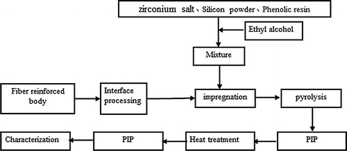
3D Cf/ZrC–SiC composites were prepared by PIP process using zirconium salt, silicon powder and phenolic resin as raw materials. The experimental procedure for preparation of 3D Cf/ZrC–SiC composites is shown in . The fabrication of 3D fiber bodies has been reported in our previous studies [Citation10]. The fabrics were then impregnated in the slurry which consisted of zirconium carbonate, Si powder and thermosetting phenolic resin using ethyl alcohol as solvent. The heat-treatment process is in accordance with the process of Ref. [Citation10]. During the in situ reaction, zirconium carbonate is discomposed into ZrO2. ZrO2 powders and Si powders were allowed to react with the carbon from the pyrolysis of thermosetting phenolic resin to form ZrC and SiC, respectively.
Fig. 1 Experimental procedure for preparation of 3D Cf/ZrC–SiC composites.
3 Results and discussion
3.1 Raw material characterization
shows the SEM images of zirconium carbonate before and after heat treatment at 1500 °C for 60 min. Zirconium carbonate is used because it is cheaper than zirconium oxide. It is shown from (b) that the particle sizes of the zirconium carbonate are approximately 2 μm, with a nearly spherical morphology. However, agglomeration exists. After heat treatment, the particle sizes become smaller and the shape has changed, as shown in (d), and agglomeration still exists. The phenomenon of sintering can be found from the image. It is indicated from the EDS results ((a)) that the main elements are C, O and Zr. From (c), the ZrO2 is formed after heat treatment. In the heat-treatment process, several reactions may occur as follows:(1)
(1)
(2)
(2)
Fig. 2 The SEM images of zirconium carbonate before (a and b) and after (c and d) heat-treatment at 1500 °C for 60 min.
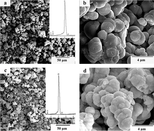
Among the above reactions, zirconium carbonate is discomposed and H2O will be evaporated at the relative low temperature. With the temperature increasing, the bond between ZrO2 and CO2 will brake. Finally, CO2 will be evaporated. As indicated by the above reactions, the weight loss accompanied in the heat-treatment process is caused by the evaporation of H2O and CO2. The results of the above reactions are consistent with the EDS analysis.
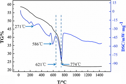
The DSC (differential scanning calorimeter) and TG (thermo-gravimetric analysis) results of zirconium carbonate from 0 °C to 1450 °C are shown in . A weight loss was seen from the curve of TG from the beginning to 774 °C. However, the weight from 774 °C to 1450 °C remained unchanged. It can be concluded that zirconium carbonate has been decomposed at 1450 °C. Meanwhile, the curve of DSC showed three prominent endothermic peaks at this temperature range. The first peak means that the bound water is removed from the raw material from 0 °C to 271 °C. As shown in reaction Equation(1)(1)
(1) , the crystal water volatilized at 586 °C. Thus, the second peak is formed. With the increasing temperatures, the reaction Equation(3)
(3)
(3) began to play a major role. The weight continued to decrease because of the evaporation of CO2. The curve of TG is consistent with the result of DSC.
Fig. 3 DSC/TG analysis of zirconium carbonate from 0 °C to 1450 °C.
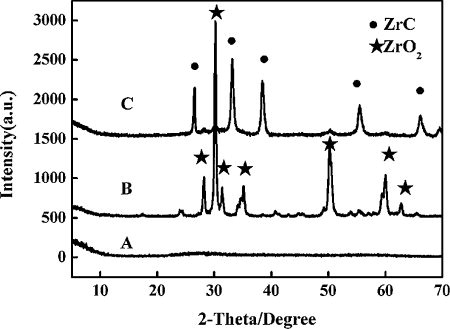
The XRD patterns of the zirconium carbonate obtained by drying at 130 °C for 30 min (A) and 1500 °C for 60 min (B) are shown in . Curve C represents the XRD pattern of the mixture of zirconium carbonate and thermosetting phenolic resin pyrolyzing at 1500 °C for 60 min. After holding at 130 °C for 30 min, XRD diffraction identified amorphous phase. However, after heating at 1500 °C for 60 min, only the ZrO2 peaks emerge. It is indicated that zirconium carbonate can be a Zr source to fabricate ZrC. Meanwhile, it can be seen that the ZrO2 peaks disappear, indicating the completion of ZrO2 conversion into ZrC, as shown in (C). Thus, it is feasible that ZrC can be obtained with zirconium carbonate as raw material at 1500 °C for 60 min.
Fig. 4 The XRD patterns of the zirconium carbonate obtained by drying at 130 °C for 30 min (A), 1500 °C for 60 min (B) and after reaction with phenolic resin (C).
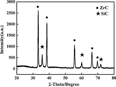
The XRD pattern of the ZrC–SiC matrix with zirconium carbonate, thermosetting phenolic resin and Si powder as raw materials after heat treatment at 1500 °C for 60 min is plotted in . It can be concluded from the diffraction peak that the main phases existing in the powders are ZrC and SiC. ZrC and SiC are obtained through the reaction between zirconium carbonate or Si powder and thermosetting phenolic resin, respectively. Some possible reactions during the pyrolysis and the heat-treatment process are as follows:(3)
(3)
(4)
(4)
(5)
(5)
(6)
(6)
(7)
(7)
Fig. 5 The XRD pattern of the ZrC–SiC matrix with zirconium carbonate, thermosetting phenolic resin and Si powder as raw materials after heat treatment at 1500 °C for 60 min.
The SEM images of the ZrC–SiC matrix heated at 1500 °C for 60 min are shown in . It is shown that the SiC phases (dark background in the backscattered electron micrograph) are regularly dispersed in the ZrC matrix (white background), as indicated by the arrows. From the images, the particle sizes of the ZrC matrix range between 100 and 200 nm and those of SiC are about 10 μm. However, agglomeration still exists.
Fig. 6 The SEM images of the ZrC–SiC matrix heated at 1500 °C for 60 min: (a and b) using zirconium salt as raw material, and (c) using polycarbosilane and ZrC precursor as raw material.
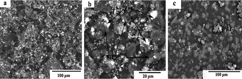
In our previous studies, ZrC–SiC matrix was fabricated by means of a liquid precursor conversion method using ZrC precursor and polycarbosilane [Citation12] and via in situ reaction by using zirconium powders, silicon powders and phenolic resin as raw materials [Citation13]. The crystal size and morphology of the synthesized matrix were researched. However, the prices of raw materials for the above two methods are expensive, compared with that of zirconium carbonate. The comparison of ZrC–SiC matrix fabricated using zirconium salt and ZrC precursor as raw material is shown in (c). From the image, it can be concluded that a ZrC–SiC matrix can be obtained through the reactions between zirconium carbonate, silicon powders and phenolic resin. The cost of preparation is reduced greatly. Moreover, the ZrC phase is dispersed evenly in the SiC phase. The temperature of fabrication is relatively lower than those of the previous methods.
3.2 Microstructures of 3D Cf/ZrC–SiC composite
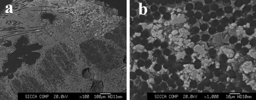
The SEM images on the polished cross-sections of 3D Cf/ZrC–SiC composite are shown in . The fact is proved that 3D Cf/ZrC–SiC composite could be fabricated completely using zirconium salt, silicon powder and phenolic resin as raw materials. ZrC phase (a white background in the backscattered electron micrographs) and SiC phase (a gray background) are formed through the reaction between zirconium carbonate, silicon powder and phenolic resin. From (a), the composite shows dense microstructure even through few micropores of impurities is observed. Based on (b), ZrC phase is inserted into not only the inter-bundle areas but also the intra-bundle areas. Thus, this method is feasible to fabricate 3D Cf/ZrC–SiC composite. In our future work, the properties of Cf/ZrC–SiC composite would be more consistent.
Fig. 7 SEM images on the polished cross-sections of 3D Cf/ZrC–SiC composite: (a) polished cross-sectional image and (b) larger magnification.
4 Conclusions
In conclusion, a ZrC–SiC matrix was fabricated by means of in situ reaction, using zirconium carbonate, silicon powders and phenolic resin and their pyrolysis at 1500 °C for 60 min. The ZrC–SiC matrix had a small average crystalline size (<50 μm). However, agglomeration still exists. On the whole, The ZrC–SiC matrix can be fabricated for ceramic matrix composites at low cost and rapidly, using zirconium salt as raw materials. The purpose of this research is to fabricate the Cf/ZrC–SiC composite using zirconium salt as raw materials. The 3D Cf/ZrC–SiC composites were successfully fabricated using zirconium salt, silicon powder and phenolic resin as raw materials.
Acknowledgments
The authors appreciate the financial support of the National Natural Science Foundation of China under the Grant Nos. 51172256, 51142010, and 51372099 and the Doctoral Fund of University of Jinan (XBS1310). The authors also appreciate the financial support by Program for Scientific research innovation team in Colleges and universities of Shandong Province.
Notes
Peer review under responsibility of The Ceramic Society of Japan and the Korean Ceramic Society.
References
- Q.G.LiH.J.ZhouS.M.DongZ.WangJ.S.YangB.WuJ.B.HuCeram. Int.386201252715275
- N.PadmavathiS.KumariV.V.B.PrasadJ.SubrahmanyamK.K.RayCeram. Int.35200934473454
- Z.WangS.M.DongX.Y.ZhangH.J.ZhouD.X.WuQ.ZhouD.L.JiangJ. Am. Ceram. Soc.9110200834343436
- Z.WangS.M.DongY.S.DingX.Y.ZhangH.J.ZhouJ.S.YangB.LuCeram. Int.372011695700
- L.F.ChengY.D.XuL.T.ZhangX.W.YinMater. Sci. Eng. A30012001219225
- Q.G.LiS.M.DongZ.WangP.HeH.J.ZhouJ.S.YangB.WuJ.B.HuJ. Am. Ceram. Soc.94201212161219
- Q.G.LiS.M.DongZ.WangG.P.ShiCeram. Int.39201347234727
- Q.G.LiS.M.DongZ.WangJ.B.HuB.WuH.J.ZhouP.HeJ.S.YangCeram. Int.392013877881
- G.J.ZhangZ.Y.DengN.KondoJ.F.YangT.OhjiJ. Am. Ceram. Soc.839200023302332
- G.J.ZhangJ.F.YangM.AndoT.OhjiJ. Eur. Ceram. Soc.2214/15200225512554
- G.J.ZhangM.AndoJ.F.YangT.OhjiJ. Eur. Ceram. Soc.2422004171178
- Q.G.LiH.J.ZhouS.M.DongZ.WangP.HeJ.S.YangB.WuJ.B.HuCeram. Int.38201243794384
- Q.G.LiS.M.DongZ.WangG.P.ShiY.MaH.J.ZhouZ.WangCeram. Int.38201424832488