
Abstract
Optimal matching of an electrode array to the cochlear anatomy plays a key role in bringing the best benefit of CI technology to the users. Even within the category of normal anatomy cochlea, the size variation is huge justifying MED-EL’s FLEX electrode array to be available in five different lengths. Within the malformed inner-ear category the anatomical variation is huge, convincing MED-EL to custom-design the electrode array as per the request from the operating surgeons. Thanks to G. Bredberg, M. Beltrame, L. Sennaroglu, J. Gavilan, S. Plontke, T. Lenarz, J. Müller, and few others for their valuable suggestions on unique electrode designs satisfying various needs. Translational research efforts at MED-EL in cooperation with CI surgeons from across the world led to the implantation of a variety of electrode array designs in patients with special cochlear needs.
Graphical Abstract
Chinese abstract
在为CI使用者带来CI技术的最大益处方面, 与耳蜗解剖结构匹配的电极阵列的最佳放置起着关键作用。比以往任何时候都更清楚的是, 在需要不同设计的电极阵列的人群中, 人工耳蜗的解剖结构差异很大。在正常解剖型耳蜗类别中, 尺寸变化巨大, 证明MED-EL的FLEX电极阵列提供六种不同的长度是必须的。在畸形的内耳类别中, 解剖学差异很大, 这使MED-EL能够根据手术医生的要求定制设计电极阵列。感谢Bredberg教授、Beltrame教授、Sennaroglu教授、Gavilan教授、Plontke教授、Lenarz教授和Müller教授, 以及其他几位, 为满足耳蜗各种需求的独特电极设计提出的宝贵建议。本章展示了MED-EL与来自世界各地的CI外科医生一起进行的转化研究工作。这些研究导致为有特殊耳蜗需求的患者植入各种电极阵列设计。
7.1. Introduction
One of the success-determining factors of the cochlear implant (CI) treatment lays in electrode array design which mimics the cochlear anatomy. More precisely, this has to do with the fact that the electrode array bridges neural elements with the stimulating part of the implant that gets input from the audio processor. The neural elements then carry the electric signal to the auditory cortex, helping patients to perceive sound.
The cochlea is so unique in its size, shape, anatomy and pathology that one electrode array design or its length may hardly match with every variation. Some cochleae, for example, lack a proper neural connection between cochlea and the next level in the auditory pathway which might be hard to evaluate from the clinical radiographs, and meningitis-infected cochleae develop intracochlear fibrous tissue or even a new bone formation, posing a challenge for the electrode array insertion.
Like other medical fields, the CI field is also evolving towards personalised treatment, and since 1990, MED-EL has developed the broadest cochlear electrode portfolio on the market, tailored for every cochlear variation. Such personalised approach would not be possible without strong and valuable scientific collaboration with expert surgeons across the world, and the combination of innovative CI electrode designs with atraumatic surgical techniques ensures high performance with hearing restoration.
This article brings forward the science behind MED-EL’s special electrode array designs and the corresponding patient benefits.
7.2. FLEX electrode array series
The very first multichannel microelectronics CI developed by Erwin and Ingeborg Hochmair () was implanted by Prof. Kurt Burian in Vienna on 16 December 1977 already encompassed a quite soft long electrode.
Figure 1. Dr. Ingeborg Hochmair, who developed the electrode concept with two rows of contacts on opposite sides of the silicone electrode carrier.

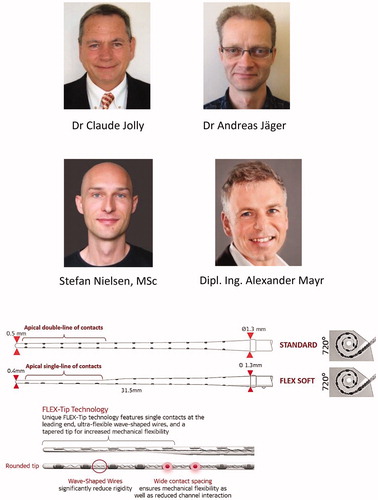
This electrode had two rows of contacts on opposite sides of the silicone electrode carrier. The contacts were arranged in this manner such that independent of possible rotations during electrode insertion, 1 of the 2 contacts in opposite rows would end up underneath the fibers in the osseous spiral lamina and/or the ganglion if the ones in the lamina should not be there anymore [Citation1]. After MED-EL hired its 1st team member in 1990, the C40 implant system was developed. It had eight stimulating channels with a double line of electrode channels and was implanted from January 1994 on. The number of channels and therefore contacts were increased to twelve double-lined channels in 1996. The electrode array was named STANDARD, and it measured 31.5 mm in length, upholding its clinical existence up to this day. The STANDARD electrode array was evidenced as a significant choice for structure preservation, as recently reported by Sierra et al. [Citation2]. As hearing and structure preservation became the objective in every CI surgery, the STANDARD electrode array was further fine-tuned by reducing its diameter at the apical end and by changing the five apical double-lined channels to single-line channel distribution, but retaining its original array length of 31.5 mm. The improved electrode version was named FLEXSOFT™ in 2004. Dr. Jolly, Dr. Jäger, Mr. Nielsen and Mr. Mayr from MED-EL were highly involved in the development of the FLEX electrode array series (.
Figure 2. Engineers from MED-EL who conceived and realised the FLEXSOFT™ electrode array (top panel). STANDARD and FLEXSOFT™ electrode arrays comparison showing double line and the single line of channels, respectively, at the apical end. Wavy wires and wide contact spacing are unique features on MED-EL’s electrode arrays. Image courtesy of MED-EL.
Until 2004, mainly patients with profound sensorineural hearing loss (SNHL) were considered as CI candidates, and therefore the 31.5 mm long electrode array was necessary to cover the entire frequency range. Since the introduction of the combined electric and acoustic stimulation (EAS™) concept for patients with partial deafness and functional low-frequency residual hearing that can be amplified with the hearing aid (HA), there was a need for a medium length, yet flexible, electrode array. To satisfy this need, MED-EL came up with the FLEX24™ electrode array, which measures 24 mm in length, and which was successfully implanted in a paediatric patient with low-frequency hearing preservation in 2004. Over the years, several research studies have pointed out that the human cochlea is highly variable in its size and shape [Citation3,Citation4] and that prompted MED-EL to introduce other variants to FLEX series with array lengths of 20-, 26- and 28-mm () to match even more variations of cochlear geometry. Choosing an electrode array based on cochlear size, as measured from the preoperative radiographs, and hearing level determined by auditory thresholds (), could lead to the personalised CI electrode treatment to which MED-EL is highly committed.
Figure 3. FLEX electrode array series with different array lengths (in addition to the previously mentioned FLEXSOFT™), offering various angular insertion depths (A). Audiograms of various hearing loss conditions and proposed electrode array lengths (B). Image courtesy of MED-EL.
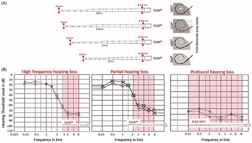
As shown in , the atraumatic features of FLEX electrode arrays include wavy wires, rounded tip, wide contact spacing, and smaller cross-sectional dimensions that result in very minimal electrode array-related complications inside the cochlea, compared to electrodes from other CI brands [Citation5,Citation6].
7.3. Special electrodes for abnormal inner ear anatomies and complications
Normal anatomy inner ear as seen from the clinical radiographs in axial and coronal views would show the clear presence of three different cochlear turns, three semi-circular canals, an internal auditory canal having a structural connection with the cochlea, and a <1 mm thick vestibular aqueduct ().
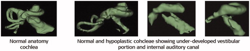
Figure 4. Normal anatomy cochlea as seen in oblique coronal view (A) and in axial view (B). Image courtesy of MED-EL.

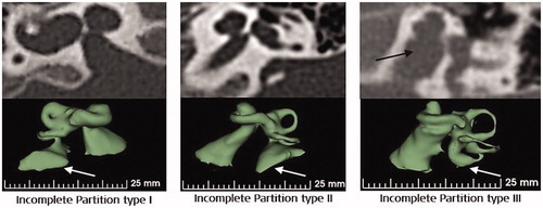
Deviation from the typical presence of any of the abovementioned inner ear structures may be brought under abnormal anatomy medical term. Literature has evidenced the presence of abnormal inner-ear anatomies with an incidence rate varying from 15% to 30% among the SNHL population [Citation7,Citation8]. Well reported inner ear malformation types include incomplete partition (IP) type I, type II (Mondini’s deformation), type III (also called x-linked malformation), cochlear hypoplasia (CH) and common cavity (CC), as shown in .
Figure 5. Inner-ear malformation types seen in 2-dimensional (2D) and 3-dimensional (3D) views. Image courtesy of MED-EL.
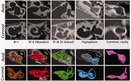
Of all the malformation types, CC is considered as the most severe as the cochlear portion cannot be distinguished from the rest of the inner-ear structures, making it difficult to insert a standard electrode safely without risk of deviating to the wide internal auditory canal (IAC) opening. CH (also known as underdeveloped cochlea) is evidenced in various sizes, shapes and degrees of severity and again, a generic electrode array design may not be a good match for each of these variations.
IP type III is characterised by the clear absence of modiolus trunk and the presence of a wide IAC opening at the cochlea itself, hindering it from a smooth electrode array insertion. Because of the wide IAC opening, a cerebrospinal fluid (CSF) gusher is expected in the majority of IP type III cases, and if untreated, then the CSF leakage could lead to the potentially fatal meningitis infection. IP type I and IP type II malformations have very minimal, from up to 50% and up to 75% of the basal turn developed, respectively, and the remaining part of the cochlea is in a cystic form. In such cases, an electrode array choice which to achieve an angular intracochlear insertion of 360° is preferable, and these two types of malformations are mostly characterised by enlarged vestibular aqueduct (EVA). EVA is associated with mild to severe endolymphatic oozing when the cochlea is opened for electrode array insertion.
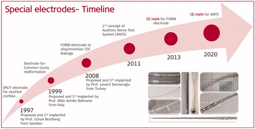
An ossified cochlea is mainly a result of meningitis infection or a consequence of a temporal bone fracture – which the sooner it is detected, the easier the CI electrode array may be implanted before the outset of cochlear ossification. In extreme conditions, such as in a complete cochlear ossification, a regular electrode array insertion may not be possible. Apart from these well-reported inner ear malformation cases, there are other less frequent complications, including inadvertent facial nerve stimulation (FNS), thin cochlear nerve with ambivalent capabilities of carrying electric stimulation, intralabyrinthine cholesteatoma which requires partial dissection of the cochlear promontory to be removed, and other conditions. MED-EL has always made sure that every cochlear condition is addressed with utmost importance. In association with clinicians, MED-EL did everything possible to come up with unique/special electrode array solutions to match with every variation of the cochlear anatomy and to avoid or minimise the above-listed complications.
7.3.1. Cochlear ossification and special electrode
Ossification inside the cochlea could be a result of bacterial infection entering the cochlea through the cochlear aqueduct (CA) () which is connected to the cochlea close to the round window (RW) membrane.
Figure 6. Cochlear aqueduct (CA) canal connecting to the basal turn of the cochlea near the RW entrance, as seen in 2D and 3D views (A). Temporal bone fracture and resulting ossification inside the cochlea (B). Different degrees of ossification (C) [Citation9]. Image (A and B) courtesy of MED-EL., and (C) reproduced by permission of Taylor and Francis Group.
![Figure 6. Cochlear aqueduct (CA) canal connecting to the basal turn of the cochlea near the RW entrance, as seen in 2D and 3D views (A). Temporal bone fracture and resulting ossification inside the cochlea (B). Different degrees of ossification (C) [Citation9]. Image (A and B) courtesy of MED-EL., and (C) reproduced by permission of Taylor and Francis Group.](/cms/asset/9126a8f6-c34e-4649-a7b0-1337f6b584cf/ioto_a_1888506_f0006_c.jpg)
Ossification is also seen in cases that encountered trauma leading to temporal bone fracture, as shown in . Whatever be the cause of ossification, the sooner it is detected, the fewer challenges it poses with inserting an electrode array. In extreme conditions, such as in a complete cochlear ossification, inserting a generically designed electrode array with a standard surgical approach may not be possible. The degree of ossification can vary from very mild at the RW membrane part only, to severe or complete cochlear ossification [Citation9], as seen in . Inserting an electrode array to each of these ossified cochlear variations requires careful planning. Ossification at the RW or at the basal turn may be removed by drilling through it, and the electrode array with the most suitable length may be implanted with minimal or no effort. However, if the ossification has reached the middle turn or the entire cochlea, then the standard surgical insertion of a regular electrode array may not be possible.
In 1997, Prof. Bredberg from Karolinska Institute in Stockholm in Sweden came up with a special electrode array concept that featured a double array with short lengths (). MED-EL has developed it and named it as SPLIT GB, where GB stands for Göran Bredberg. This electrode was designed to be used in combination with a special surgical technique whereby two openings into the ossified cochlea, corresponding to the upper and lower basal turns, are made to accommodate the two branches of the electrode, as shown in .
Figure 7. Prof. Göran Bredberg, who proposed the concept of a double branch split electrode. Two-branch split electrode with more extended branch carrying seven contacts, and shorter branch having five contacts (A). Image showing two drilled accesses in upper and lower part of the basal turn, to place the two-branch split electrode arrays (B). Image courtesy of MED-EL.
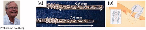
The surgical technique is performed as follows: an inferior cochleostomy that corresponds to the scala tympani in the lower basal turn, and a superior cochleostomy just in front of the oval window (OW), corresponding to the upper basal turn. Such placement results in the coverage near the spiral ganglion and the modiolus, and the two electrode array branches are programmed for stimulation from base to apex. Two patients were implanted with this special electrode array in the same year, and they both reported good sound perception and pitch discrimination [Citation10]. Over time both, the split electrode array and the surgical approach were widely accepted by clinicians across the world and were implanted in approximately two hundred patients worldwide.
In 2004 and 2005, reports on the sound and speech perception with split electrode implantation came from the University of Texas Southwestern and Utah Health Sciences Centre, USA [Citation11,Citation12] ().
Figure 8. Surgeons from two different centres in the USA who implanted the SPLIT GB electrode array in patients with fully ossified cochlea and reported the postoperative hearing results.

The Texas group evaluated eight paediatric patients, and the Utah group four patients (two adults and two paediatric) with meningitis infection-related inner-ear ossification who were implanted with SPLIT GB electrode array. After implantation, the eight patients from Texas’ study showed a decrease in aided speech detection thresholds (SDT) at six months postoperatively, compared to the preoperative scores, and the Infant-Toddler Meaningful Auditory Integration Scale (IT-MAIS) scores increased from 8.0 to 23.8 on average. As for patients from the Utah study, the first patient (adult) showed an improvement with the aided Pure Tone Average (PTA) by 19 dB, and the HINT scores increased from 0% to 72%. The second patient (adult) had a 44 dB gain in aided PTA by the twelfth postoperative month. However, the latter patient showed no significant improvement in speech perception but continued to use the implant as it was helpful with engaging in oral communication. Third and fourth patients (both paediatric) had undetectable SDT before implantation, but by the twelfth month after surgery, the SDT improved to reach 15 dB and 45 dB, respectively. IT-MAIS scores increased from the preoperative value of 4 for both patients to 35 and 31, respectively. The authors of the two studies concluded that split electrode array implantation was a safe and effective treatment option in the case of complete cochlear ossification.
Recently, in 2018, Prof. Schmutzhard and his colleagues from the University of Innsbruck in Austria reported on the successful implantation of the SPLIT GB electrode array () assisted by an electromagnetic navigation system (EMNS) in a patient with a very advanced form of otosclerosis [Citation13]. The mean aided threshold determined at seven months after surgery was 32 dB, and the patient reported improved understanding of speech at first switch-on. At the follow-up fitting session, speech intelligibility of monosyllables had improved from 0% to 50%, and from 0% to 60% at presentation levels of 65 dB and 75 dB, respectively. These pieces of evidence encourage that in extreme ossified cochlear conditions in which placing the standard electrode is not possible, the SPLIT GB electrode may be implanted confidently.
Figure 9. Clinicians from Innsbruck clinic, Austria, implanted the SPLIT GB electrode array in their patient with advanced otosclerosis, and a postoperative image is showing the proper placement of the electrode. Postoperative x-ray image showing the placement of the double branch electrode [Citation13]. AE: apical electrode, MO: modiolus, BE: basal electrode. Reproduced by permission of Wolters Kluwer Health, Inc.
![Figure 9. Clinicians from Innsbruck clinic, Austria, implanted the SPLIT GB electrode array in their patient with advanced otosclerosis, and a postoperative image is showing the proper placement of the electrode. Postoperative x-ray image showing the placement of the double branch electrode [Citation13]. AE: apical electrode, MO: modiolus, BE: basal electrode. Reproduced by permission of Wolters Kluwer Health, Inc.](/cms/asset/7bd4131e-cc25-4e76-a806-7e641b2a8314/ioto_a_1888506_f0009_c.jpg)
The specially designed SPLIT GB electrode array was made and remains available as a custom-made device (CMD) under the council directive 93/42/European Economic Community (EEC) [Citation14]. CMD relates to any device specifically made per a duly qualified medical practitioner’s written prescription which gives, under his or her responsibility, specific design characteristics and is intended for the sole use of a specific patient. Under CMD, even if the device is not approved by a notified body, such as by FDA or TÜV, it is still possible to implant the device in patients, provided that the device is qualified by the appropriate laboratory tests by the device manufacturers.
7.3.2. Common cavity-type malformation and special electrode
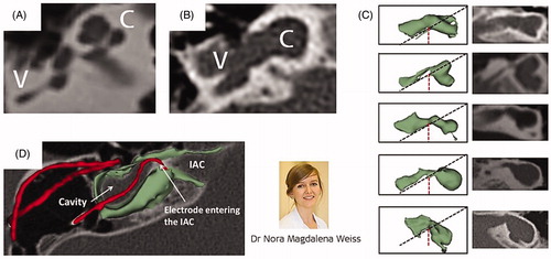
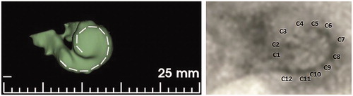
The CC malformation was first described by Edward Cock [Citation15] in 1838 as a disruption in the differentiation of inner ear structures during the fourth and fifth week of gestation [Citation16]. show samples of normal cochlear anatomy, and of the classic CC, respectively. The CC is seen without complex intracochlear neural structures, and instead, it is only filled with cochlear fluid. Neural elements are likely laying in the walls of the cavity, and therefore an ideal electrode array placement would be along the cavity wall. Cochlear aplasia (absence of cochlea) with a dilated vestibular cavity is the result of developmental arrest in the third week of gestation [Citation15]. This type of vestibular cavity with an evident absence of the cochlear portion is often mistakenly considered as CC, as shown in [Citation17]. Placing a straight electrode array inside a classic CC or in a dilated vestibular cavity with cochlear aplasia carries the risk of electrode entering the wide IAC, as shown in .
Figure 10. Cochlea with normal anatomy as seen in axial view (A); classic CC malformation showing both, cochlea and vestibule fused to form a single cavity (B); absence of cochlear part and presence of vestibular cavity (C); incorrect insertion of an electrode array which reached the IAC (D). Image courtesy of MED-EL. Image of Dr. Nora Magdalena Weiss from University of Rostock, Germany, who studied the difference between classic CC and cavity that represents vestibular portion with the clear absence of cochlear portion.
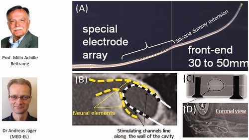
In 1999, Prof. Beltrame from Rovereto in Italy came up with a special electrode design that would ensure no part of the electrode would enter the IAC, and it was Dr. Jäger from MED-EL who realised the concept into a functional device. captures the special electrode array, which includes a silicone dummy extension at the tip to ensure the stimulating channels lining along the cavity wall where the neural elements are present (). Bench experiments showed the proper placement of the electrode array inside the plastic CC model (). This special electrode was first implanted in the year 1999 in a two-year-old girl who was suffering from congenital profound SNHL in her right ear [Citation18]. Instead of using a regular posterior tympanotomy approach to reach the inner ear, Prof. Beltrame reached the cavity through a trans-mastoid double posterior labyrinthotomy approach. At this point, the silicone dummy part was introduced into the superior opening until it was seen through the inferior opening. With the help of a hook, the silicone dummy end was pulled out of the inferior opening and followed by gentle pushing of the active part of the electrode array through the superior opening until the electrode array aligned against the cavity wall, as shown in . Small pieces of connective tissue were then packed around the electrode array to close the two labyrinthotomy sites. Two months after the device activation, the child was responding to environmental sounds and showed good results in the detection and identification of sound. Over time, this special electrode design and the surgical approach were well accepted by clinicians across the world.
Figure 11. Special electrode array with silicone dummy extension conceptualised by Prof. Beltrame and realised by Dr. Andreas Jäger (A). Neural elements are believed to be present along the cavity wall, as shown by the yellow dotted line (B). X-ray image of the special electrode in a plastic cavity model (C); postoperative image showing special electrode inside the CC type cochlea (D). Image (D) courtesy of Dr. Mary Shanks, Kilmarnock.
In 2013, a multicentric study from Italy, Australia, Spain, UK, Syria and the USA reported on long term speech perception and audiological performance of children with CC type cochleae implanted with MED-EL’s special electrode array [Citation19] ().
Figure 12. Clinicians from 1Sydney Medical School, Australia, 2Hospital Nino Jesus, Spain, 3Medical College Damascus University, Syria, 4Beth Israel Medical Center, USA, 5University of Southampton, UK, 6Southmead Hospital, UK, 7Hospital San Cecilio, Spain, 8Crosshouse Hospital, UK, 9Krankenhaus Martha-Maria München, Germany, 10Hospital Son Espases, Spain, implanted the CC special electrode to their patients and reported on patients’ speech and audiological performance.

Altogether nineteen patients with CC malformation type, accompanied by CSF gusher, were included in the multicentric study in eleven different centres across the world. All patients were implanted with MED-EL’s special electrode. Categories of Auditory Performance (CAP) and Speech Intelligibility Rating (SIR) were performed to evaluate the listening skills rated from 0 (worst) to 7 (best) and speech intelligibility rated from 1 (worst) to 5 (best) at various time intervals, starting at one month before the surgery, at the first fitting, at 1, 3, 6, 12 and 18 months, and at 2, 3, 4 and 5 years after the first fitting. The auditory perception results showed a chronological improvement over time, and CAP was found to be strongly associated with the SIR only after six months following the device activation (). Two years after the implantation, median scores of CAP with 4/7 and of SIR with 2/5 were observed. The authors concluded that such special CI is a safe and effective treatment option in children with CC, and the majority of subjects showed significant benefits with audiological development after implantation.
Figure 13. Long term audiological and speech performance as evaluated through categories of auditory performance (CAP) and speech intelligibility rating (SIR) scores of patients implanted with CC special electrode from various clinics across the continents [Citation19]. Statistical test: Friedman test to check for a significant difference over the test period. Reproduced with permission of Elsevier Ireland Ltd.
![Figure 13. Long term audiological and speech performance as evaluated through categories of auditory performance (CAP) and speech intelligibility rating (SIR) scores of patients implanted with CC special electrode from various clinics across the continents [Citation19]. Statistical test: Friedman test to check for a significant difference over the test period. Reproduced with permission of Elsevier Ireland Ltd.](/cms/asset/92dd661d-a58b-45ba-830d-57e0ca3ccb6a/ioto_a_1888506_f0013_b.jpg)
Under the CMD council directive [Citation14], MED-EL delivered the CC special electrodes that were implanted so far about two hundred children until today (2021). The main risk associated with the cochlear implantation in general in CC malformation condition is the chance of the electrode entering the IAC, and this special electrode design aims to avoid that risk while ensuring the electrode array placement as close as possible to the cavity wall where the neural elements are present [Citation20].
7.3.3. Cochlear hypoplasia and short electrode array
Cochlear hypoplasia (CH) is defined as an underdeveloped cochlea, in which the cochlea and vestibule can be differentiated from each other but where cochlear size is smaller than the average. CH has the developmental arrest occurrence in the sixth week of gestation [Citation15]. The size of the cochlear portion varies a lot from as tiny as a small bud () to as big as two turns of the cochlea ().
Figure 14. CH with different degrees of severity, starting from tiny bud-like appearance (A) to little development of the cochlea (B), to half of the basal turn (C, D), and one full turn of the cochlea (E, F). Image courtesy of MED-EL.
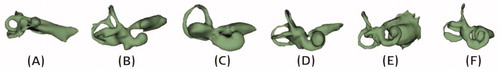
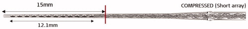
The best-suited electrode array for such underdeveloped cochleae must be chosen based on the available cochlear lumen length. For samples shown in , a CI might not be the choice of treatment as the cochlear size is too small for a CI electrode array placement and in such cases, an ABI may be a more suitable treatment option. MED-EL has developed a short electrode array with an active array length of 12.1 mm and named it COMPRESSED, as twelve stimulating channels were compressed within such a short length ().
Figure 15. COMPRESSED electrode with active stimulation length of 12.1 mm, which includes all twelve channels. Image courtesy of MED-EL.
A compressed electrode with an array length of 15 mm may be chosen for the samples shown in , whereas an array length of 20–24 mm may be chosen for samples shown in . shows a 20 mm long electrode array covering 360° of angular insertion depth in a hypoplastic cochlea. Cochlear hypoplasia could be associated with the absence of vestibular portion and sometimes with hypoplastic IAC, which requires detailed analysis, based on the intraoperative images. As far as the CI electrode array length is concerned, choosing a length based on the cochlear size would ensure its optimal placement.
Figure 16. Hypoplastic cochlea with one full turn developed and 20 mm long electrode array covering 360° of angular insertion depth (right-hand side image: courtesy of Dr. Classen, Bloemfontein, South Africa).
7.3.4. Incomplete partition type malformations and special electrode array
Incomplete partition (IP) type malformation has three sub-types, namely type I, type II and type III. IP type I is also known as cystic cochleovestibular malformation, where the cochlea has no bony modiolus, resulting in an empty cystic cochlea and is accompanied by a dilated cystic vestibule with the developmental arrest at the fifth week of gestation [Citation16]. IP type II has the developmental arrest at the seventh week of gestation [Citation16], and as a result, the cochlea and the vestibular portion are entirely separated. In such cases, the cochlea consists of 1.5 turns, although the apical and the middle turns are undifferentiated in the form of a cyst. The vestibular aqueduct is mostly seen enlarged () in both, IP type I and type II, which could lead to endolymphatic oozing when the cochlea is opened for electrode insertion. CSF gusher is often accompanied by IP type III malformation as it has a wide IAC that opens directly to the cochlear basal turn. Leakage of cochlear fluid following the CI surgery could lead to infections, and the surgical technique of tightly packing the cochlear opening with connective tissue is one possible way to address this issue.
Figure 17. Three different types of incomplete partition type malformation showing the presence of enlarged vestibular aqueduct, as pointed by the white arrow mark. Image courtesy of MED-EL.
In 2008, Prof. Sennaroglu from the Hacettepe University in Ankara in Turkey came up with the concept of a cork-like insertion stopper type electrode that would provide the additional cochlear sealing capability to the electrode array ().
Figure 18. FORM electrode array with cork type insertion stopper (A). CORK stopper dimensions (B) (Image courtesy of MED-EL). Ring of fascia loaded on to the electrode array (C, D). Image showing the CORK type stopper sealing the cochlear opening (E) [Citation21]. Reproduced by permission of Elsevier Ireland Ltd.
![Figure 18. FORM electrode array with cork type insertion stopper (A). CORK stopper dimensions (B) (Image courtesy of MED-EL). Ring of fascia loaded on to the electrode array (C, D). Image showing the CORK type stopper sealing the cochlear opening (E) [Citation21]. Reproduced by permission of Elsevier Ireland Ltd.](/cms/asset/867879bf-f254-4a72-9d78-239d816be577/ioto_a_1888506_f0018_c.jpg)
The CORK stopper has a diameter of 1.9 mm at the thickest seal part and 0.8 mm at the thinnest part with a length of 2.4 mm (). For these CORK dimensions to seal the cochlear opening effectively, a ring of muscle tissue around the electrode array () is recommended and the size of the cochleostomy should not be larger than 1.5 mm in diameter (). MED-EL took the concept, developed the prototype and named the electrode array as CORK. Prof. Sennaroglu and his colleagues implanted the CORK electrode in fifty patients with various inner-ear malformations including IP type I, IP type II, IP type III, EVA, CH and cochlear base defect, between the years 2008–13 [Citation21]. If CSF gusher is observed during the surgery and if the CORK stopper has sealed the cochlea effectively, then no postoperative rhinorrhea is expected. Rhinorrhea is a condition in which the CSF leakage from the inner ear passes through the eustachian tube and escapes through the nasal passages. In the named study, the authors reported CSF gusher in all three IP type malformations during the surgery, and the cochlea was sealed effectively with the CORK type stopper in combination with fascia ring around the electrode array, and only one case experienced rhinorrhea ().
Table 1. Patient distribution based on inner ear malformation types, gusher and postoperative rhinorrhea [Citation21].
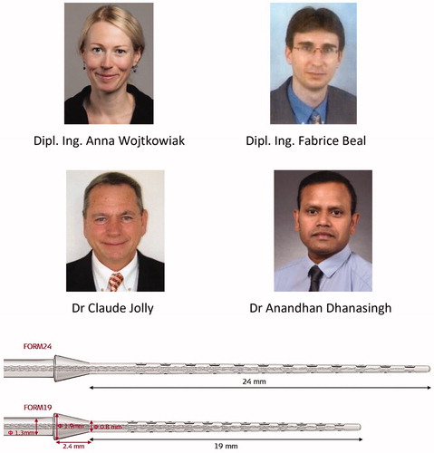
In 2013, MED-EL received CE mark for its CORK electrode, making it accessible for clinical use within the EU and countries that accept the CE mark. The CORK electrode was officially named FORM electrode and was made available in 19 mm (as FORM19™) and 24 mm (as FORM24™) array length variations. Within MED-EL, several engineers, as shown in , were involved in the FORM series development project, in which intensive laboratory tests were performed to understand the sealing properties of the cork-shaped stopper with preventing fluid leakage in phantom cochlear models. The FORM electrode arrays in combination with an effective surgical approach minimise postoperative complications associated with intraoperative CSF gusher or endolymphatic oozing.
Figure 19. Engineers from MED-EL who were involved in the development of FORM electrode series; FORM electrodes seen in two different array lengths (FORM24, FORM19). Image courtesy of MED-EL.
7.4 Intracochlear test electrode to monitor the auditory nerve functionality
The auditory nerve (AN) must be intact for hearing perception with a CI. In some instances, such as in cases of tumour removal from the IAC or in cases with severely malformed cochleae (e.g. hypoplastic cochlear type or hypoplastic IAC, as shown in ), it may be necessary to assess the viability of the AN to predict the outcome of cochlear implantation. Intracochlear electric stimulation with a CI electrode and recording electrically evoked auditory brainstem responses (eABR) via surface electrodes is a well-established method for determining the integrity of the auditory pathways [Citation22]. While the electric stimulation of the RW membrane during surgery gives a reliable estimation of the AN status, in many cases the responses may not be detected – either due to artefacts or due to higher charge levels necessary to elicit a response, but which are not possible to apply as they would exceed the safety limit [Citation23].
Figure 20. 3D images of normal-anatomy and hypoplastic cochleae, showing narrow internal auditory canal. Image courtesy of MED-EL.
For CI surgeons, a successful eABR recording straight after the electrode insertion translates to the hearing sense of the operated patient. To establish the AN integrity/functionality, an actual CI would need to be used in such challenging cases. In accommodating this with bearing the implant costs in mind, Dr. Polak and Dr. Rodrigo Dacosta from MED-EL came up with an intraoperative single-use intracochlear test electrode which may be delicately placed inside the cochlea for electric stimulation to check the integrity/functionality of AN by recording the eABR responses.
In 2011, MED-EL had its first concept () and a working prototype of the intracochlear test electrode array which measured 16 mm in length and carried one stimulating contact channel at its tip ().
Figure 21. The concept of intracochlear test electrode from paper (A) to prototype (C, D), Dr. Jolly (MED-EL) holding the prototype (B). Image courtesy of MED-EL.
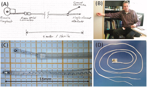
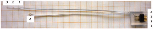
Since the electric stimulation must come from an external stimulation device to the test electrode and bringing it close to the patient with their mastoid surgically opened was thought to be unsafe at the time – therefore the excess electrode lead was made to a length of one metre long with a connector at the end (). With numerous feedbacks from the clinicians and design iterations, the final configuration featured an excess electrode lead length shortening to 10 cm, and the number of stimulating channels tripling along 18 mm array length ().
Figure 22. Final version of human intracochlear test electrode. Image courtesy of MED-EL.
In 2017, there were two studies, one from Spain led by Prof. Lassaletta along with Prof. Gavilán [Citation24] and the other from Turkey led by Prof. Sennaroglu [Citation25], that aimed to evaluate the possibilities of electrically stimulating the cochlea through the test electrode and recording eABR responses to check the AN functionality (). The study conducted in Turkey included eleven patients in total (normal anatomy: 4; incomplete partition: 4; cochlear hypoplasia: 2; common cavity: 1), and the study conducted in Spain included ten patients with normal anatomy who were all candidates for CI due to profound HL >100 dB.
Figure 23. Clinicians from 1La Paz University Hospital, Spain, 2Hacettepe University, Turkey, and engineers from MED-EL, used the test electrode in patients with a questionable cochlear nerve functionality for electric stimulation, followed by eABR recordings.

The cochlea was exposed through a regular CI surgical approach, and the test electrode was inserted with a soft surgical technique. The test electrode connector was coupled with MED-EL’s MAX Programming Interface (MAX BOX) to generate a biphasic pulse, controlled through MED-EL’s CI system fitting software MAESTRO. The eABR recording needle electrodes were placed in the appropriate anatomical location, and the lead was connected to Nicolet™ EDX Synergy Recording System (Natus; Middleton, Wisconsin, USA), triggered by the MAX BOX ().
Figure 24. Test set-up in applying the test electrode and in recording the eABR responses. Image courtesy of MED-EL.
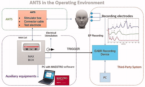
With the above test setup, eABR measurements were performed by stimulating the apical and middle channels against the external reference electrode. After the test electrode evaluation, all patients with successful eABR responses – interpreted as an indication of functional AN – received a CI, and patients without successful eABR responses – interpreted as an indication of dysfunctional AN – received an ABI. Wave V appearance in eABR response upon electric stimulation in the cochlea is seen as an indicator of healthy and normally functioning AN. In patients with normal cochlear anatomy, electric stimulation from the test electrode at various current stimulation levels showed the presence of wave V in eABR responses in both studies (). In patients with such responses, a regular CI was implanted, and electric stimulation from the CI was applied at different current levels which confirmed the wave V presence – the indicator of AN functionality (). The study performed in Turkey involved one patient with AN aplasia in whom the test electrode results showed no elicitation of wave V in the eABR responses when stimulated by the test electrode with any current levels (), and therefore the patient was implanted with ABI. With ABI stimulation, wave V started to appear in the eABR response with around 3.5 ms latency (). These two studies demonstrated the safety and benefits of employing the intracochlear test electrode in ambiguous cases with deciding between CI and ABI.
Figure 25. eABR responses recorded from normal anatomy cochlea by applying electric stimulation from the test electrode (A, C) and from CI (B, D). eABR responses not seen from cochlea with cochlear nerve aplasia when electric stimulation was applied from the test electrode (E), and responses are seen with electric stimulation from ABI (F). A and B: both from the studies from Spain [Citation24]; C–F: results from the study from Turkey [Citation25]. A and B: Reproduced by permission of Wolters Kluwer Health, Inc. C–F: Reproduced by permission of Prof. Levent Sennaroglu, Hacettepe Medical University, Turkey.
![Figure 25. eABR responses recorded from normal anatomy cochlea by applying electric stimulation from the test electrode (A, C) and from CI (B, D). eABR responses not seen from cochlea with cochlear nerve aplasia when electric stimulation was applied from the test electrode (E), and responses are seen with electric stimulation from ABI (F). A and B: both from the studies from Spain [Citation24]; C–F: results from the study from Turkey [Citation25]. A and B: Reproduced by permission of Wolters Kluwer Health, Inc. C–F: Reproduced by permission of Prof. Levent Sennaroglu, Hacettepe Medical University, Turkey.](/cms/asset/f9fd9ba0-3a50-4867-87b0-81c6e887b9d3/ioto_a_1888506_f0025_c.jpg)
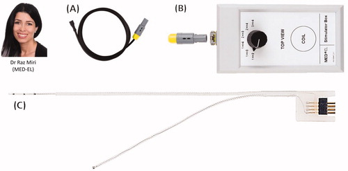
In January 2020, the intracochlear test electrode was CE marked under the product name ANTS (Auditory Nerve Test System) for use in the European Union (EU) and countries that accept CE marking. At MED-EL, it was Dr. Miri who assumed the project leader role for developing the ANTS from the CMD status to an official product until its CE marking, and the project was supported by Dipl. Ing. Beal and his colleagues. shows three parts of the ANTS.
Figure 26. Dr. Raz Miri, the project leader of the ANTS. The ANTS part. Connector cable (A) that connects the stimulator box (B) to the intracochlear test electrode (C). Image courtesy of MED-EL.
In August 2020, there was an announcement from the Washington University School of Medicine in St. Louis that they have successfully used MED-EL’s ANTS in monitoring the functionality of the AN while removing vestibular schwannomas [Citation26]. The surgical removal of schwannoma, followed by hearing restoration with CI, was performed by Dr. Wick and Prof. Buchman (), as part of the clinical trial for ANTS’ FDA approval.
Figure 27. Surgeons from the Washington University School of Medicine in St. Louis, USA who used ANTS for monitoring the AN functionality while surgically removing vestibular schwannoma, followed by cochlear implantation.

In October 2020, Prof. Arnoldner and his colleagues () from the Medical University of Vienna and Paracelsus Medical University in Salzburg, Austria, demonstrated the effectiveness of ANTS in monitoring the functionality of AN while removing vestibular schwannomas [Citation27]. Five patients were included in this study, out of which three showed positive intraoperative eABR responses during the vestibular schwannoma removal and are currently full-time CI users. The two patients who showed negative intraoperative eABR responses during the vestibular schwannoma removal had no auditory perception with CI. They concluded that the preservation of eABR seems to predict good subsequent hearing outcomes.
Figure 28. Prof. Christoph Arnoldner from the Medical University of Vienna.

7.5. Promontory stimulation to monitor the auditory nerve functionality
While the application of ANTS is one way of evaluating the AN functionality in patients selected as candidates for CI or ABI, the Promontory Stimulation (PromStim) System is another way of checking the viability of AN in patients with narrow IAC accessing the RW through the external ear canal. PromStim works in the same way as ANTS, with a difference of electric stimulation being performed at the RW niche, leaving the other test set-up identical to the ANTS. PromStim was conceptualised by a group of MED-EL engineers and clinicians from Spain and developed as a product by MED-EL at a later point ().
Figure 29. Clinicians and Engineers who conceptualised and developed the PromStim electrode as a product. 1Hospital San Cecilio, Granada, Spain, 2MED-EL Innsbruck, Austria, 3University of Valencia, Spain.

In 2018, the PromStim system was evaluated by Prof. Hempel and Prof. Müller from the Großhadern Clinic in Munich in Germany ().
Figure 30. Clinicians from Munich who were involved in the evaluation of AN functionality by the application of electric stimulation at the RW niche using PromStim.

The study comprised eleven patients in whom the CI candidacy could not be determined by regular audiological tests [Citation28]. Under local anaesthesia, a transtympanic rounded-bent tip electrode () was temporarily placed at the RW niche (), and the surface ground electrodes were placed on the zygomatic bone at the angle of the mandible.
Figure 31. Transtympanic rounded-bent tip electrode that facilitates easy placement at the RW niche (A). Illustrative representation of the transtympanic electrode placement at the RW niche (B). PromStim eABR responses for all eleven patients (C) [Citation27]. Image courtesy of MED-EL.
![Figure 31. Transtympanic rounded-bent tip electrode that facilitates easy placement at the RW niche (A). Illustrative representation of the transtympanic electrode placement at the RW niche (B). PromStim eABR responses for all eleven patients (C) [Citation27]. Image courtesy of MED-EL.](/cms/asset/09214bc4-00ee-459c-800a-b4c5adf07cff/ioto_a_1888506_f0031_c.jpg)
Biphasic alternating pulses with a phase duration of 100 µs and a stimulation rate of 34 Hz were used. The amplitude of electric pulses was increased with 100 cu/step until a response was detected. Positive PromStim eABR results were confirmed in all patients with the presence of reproducible auditory responses after electric stimulation (). These data show the validity of the PromStim system in evaluating the viability of AN in patients where regular audiological tests do not provide decisive results.
7.6. Inner ear schwannoma removal and special electrode array
Intralabyrinthine/intracochlear schwannomas are benign tumours, as shown in , which mimic various common cochleovestibular diseases, and magnetic resonance imaging (MRI) scanning is widely used for observation of tumour growth’s pace. Surgical removal of the tumour is the final solution when the tumour reaches a size that is big enough to pressurise the surrounding structures, causing symptoms like vertigo, HL, or both. Following the tumour removal, hearing restoration with CI has become the standard treatment. Surgical removal of schwannoma that is trapped deep inside the cochlea often requires dissection of a considerable portion of the cochlear capsule, as shown in , posing a challenge for the optimal placement of electrode array.
Figure 32. Intracochlear schwannoma (www.intechopen.com) (A) and partially dissected cochlea with a complete schwannoma removal (B) [Citation28]. Image B is a courtesy of Prof. Stefan Plontke, Halle, Germany.
![Figure 32. Intracochlear schwannoma (www.intechopen.com) (A) and partially dissected cochlea with a complete schwannoma removal (B) [Citation28]. Image B is a courtesy of Prof. Stefan Plontke, Halle, Germany.](/cms/asset/6bec2e30-148d-40f9-95ac-4d83abe00218/ioto_a_1888506_f0032_c.jpg)
Prof. Plontke from Martin Luther University Halle-Wittenberg in Germany is well known for his expertise in surgical removal of intralabyrinthine schwannomas, and with a joint effort between him and MED-EL, a specially shaped electrode array to fit in a dissected cochlea was successfully developed [Citation29]. As the postsurgical observation period requires periodic MRI scans to watch for new tumour developments, the implanted CI device must feature a high MRI compatibility to avoid surgical removal of the implant magnet for scanning. MED-EL’s SYNCHRONY CI System accommodates the frequent MRI exposure as it features free rotation in the presence of an external magnetic field, and thus avoiding additional surgical interventions.
The special electrode array that was designed by Dr. Dhanasingh from MED-EL for this particular cochlear condition that carried a malleable memory shaped array backbone, as shown in .
Figure 33. Special electrode with a malleable memory shaped element (A). The electrode array is shaped by rolling the electrode array over a surgical tool (B, C). Shaped electrode takes the optimal position inside the dissected cochlea (D). Postoperative image showing the shaped electrode covering two turns of the cochlea (E) [Citation28]. Image courtesy of Prof. Stefan Plontke, Halle, Germany.
![Figure 33. Special electrode with a malleable memory shaped element (A). The electrode array is shaped by rolling the electrode array over a surgical tool (B, C). Shaped electrode takes the optimal position inside the dissected cochlea (D). Postoperative image showing the shaped electrode covering two turns of the cochlea (E) [Citation28]. Image courtesy of Prof. Stefan Plontke, Halle, Germany.](/cms/asset/bd530dd9-b268-417e-88a9-4ce2c87a8bee/ioto_a_1888506_f0033_c.jpg)
This malleable element enables the electrode array shaping to surgeon’s preference (), placement into the dissected cochlea and coverage of the entire modiolus trunk (). MED-EL has delivered CI devices with the special electrode array under CMD regulations which were implanted between 2018 and 2019 in four patients with intracochlear (n = 1), intra-vestibulocochlear (n = 1) and trans-modiolar (n = 2) schwannomas. All four surgeries resulted in successful schwannoma removal and optimal electrode array placement with covering well beyond the basal turn, as seen from the postoperative radiographs (). The study involved joint efforts from clinicians from Halle and Stuttgart in Germany, Romania and in association with MED-EL ().
Figure 34. Clinicians from 1Martin Luther University Halle-Wittenberg, Germany; 2University of Medicine and Pharmacy Grigore T. Popa, Romania; 3Klinikum Stuttgart, Germany; 4Engineer from MED-EL, Austria. *Image courtesy of Prof. Stefan Plontke: Fotostelle Universitätsmedizin Halle.

The intraoperative eABR responses showed the presence of wave V in three patients, as shown in , and all four patients showed significant improvement in hearing as seen from the monosyllable word test in quiet listening condition at six months after surgery ().
Figure 35. eABR responses from the dissected cochlea with electric stimulation from the special electrode array (A). Freiburg monosyllable word test scores of patients implanted with special electrode array showing improvement in hearing performance (B) [Citation29]. Image courtesy of Prof. Stefan Plontke, Halle, Germany.
![Figure 35. eABR responses from the dissected cochlea with electric stimulation from the special electrode array (A). Freiburg monosyllable word test scores of patients implanted with special electrode array showing improvement in hearing performance (B) [Citation29]. Image courtesy of Prof. Stefan Plontke, Halle, Germany.](/cms/asset/8b96b28a-3c39-4f5f-8058-058b3a2b4e27/ioto_a_1888506_f0035_c.jpg)
While the special electrode array design offers the support needed for its optimal surgical placement, the overall surgical procedure of removing a schwannoma is complex and performed only by the most adept neuro-otologists.
7.7. List of unpublished special electrodes from MED-EL
While the special electrode array designs presented in this article are those which were publicly reported, several other, publicly undisclosed designs that were designed by Dr. Jolly and Dr. Dhanasingh from MED-EL were successfully implanted in patients under CMD regulations. They are listed below:
7.7.1. Insertion probe device to dilate cochlear fibrous tissue
Various reasons, such as meningitis infection or temporal bone fracture, result in intracochlear fibrous tissue formation, which is a natural process, but which obstructs the CI electrode array insertion.
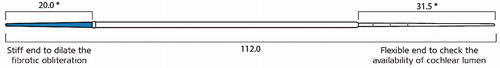
To overcome this issue, MED-EL came up with a concept of insertion probe device with two ends, as shown in , which was later developed into a commercially available product by Dipl. Ing. Wojtkowiak from MED-EL. The stiff end is useful in dilating the fibrous tissue obstruction within an intracochlear depth of 20 mm while the flexible end is checking how deep the cochlear lumen is for the electrode array placement.
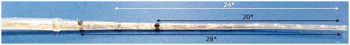
Some pathological conditions carry fibrotic obstruction beyond the basal turn of the cochlea and to address such need, another insertion device with the stiff property, as shown below, was designed with carrying three insertion depth markers (). This device was successfully used in >10 patients in obliterating fibrotic tissue inside the cochlea and was followed by regular electrode array insertion.
Figure 36. Insertion probe device with two different ends. The short blue coloured end is made stiff for a length of 20 mm to dilate the fibrous obstruction, whereas the long end is made as flexible as MED-EL’s FLEX electrode arrays to check the depth of the cochlear lumen. * Dimensions in millimetre. Image courtesy of MED-EL.
7.7.2. Electrode array with diagnostic contacts
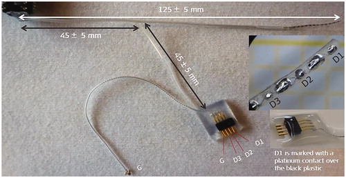
CI electrode array placement inside the cochlea with good functional low-frequency residual hearing is a delicate process. In 2014/15, it was attempted to record cochlear microphonics during the electrode insertion process. To do so, there was a need to add additional contacts within the electrode array, as proposed by Prof. Lenarz from Hannover Medical School in Germany, and MED-EL has fabricated such array with three additional diagnostic contacts, as shown in (channels D1, D2 and D3).
Figure 37. Stiff probe device with three insertion depth markers. Image courtesy of MED-EL.
7.7.3. Electrode array design to minimise facial nerve stimulation
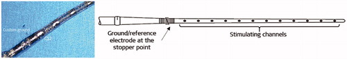
FNS, a consequence of CI electrode stimulation, represents an issue, especially with otosclerosis. FNS occurs mainly because of the widespread of the current from the promontory which reaches the FN. To minimise it, MED-EL (Dr. Jolly) came up with the concept of bringing the reference electrode close to the electrode array’s stopper, and thereby the current spread is to be kept between stimulating channels and the reference electrode at the stopper location (). Such an electrode was implanted in few patients with some success in minimising the FNS.
Figure 38. Electrode array that carries three additional diagnostic channels at the apical end of the electrode array. The diagnostic contacts are wired separately and have its connector for connecting it to external devices to record the cochlear microphonics. Image courtesy of MED-EL.
7.7.4. Short electrode array for high-frequency deafness
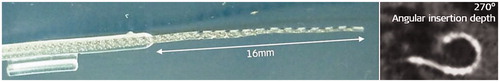
To address the need for an electrode array for patients with near-normal hearing in the low-to-middle-frequency region and with HL only in the high-frequency region, under Prof. Lenarz’s proposal, MED-EL developed a 16 mm long electrode array that would cover 270° of angular insertion depth. The electrode was implanted in a few patients ().
Figure 39. Electrode array that carries a reference electrode at the stopper point. Image courtesy of MED-EL.
7.7.5. Extra-long electrode array for extra-large cochlea
Cochlear size measurement is becoming a standard during the preoperative patient assessment, and reports are showing extra-large cochlear size with cochlear basal turn diameter in the range of 10–11 mm. To address the needs of such particular cochlear cases, Prof. Müller from Großhadern Clinic in Germany proposed to MED-EL to develop a 34 mm long electrode array () which was implanted in some patients – successful full insertion was achieved in all of them.
Figure 40. Short electrode array with 16 mm length to cover up to 270° of angular insertion depth. Image courtesy of MED-EL.
7.7.6. Compressed electrode with CORK stopper
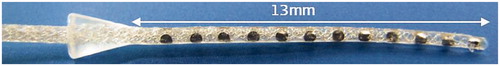
A smaller cochlear portion is usually associated with the cochlear hypoplasia type malformation. If the surgeon predicts a CSF gusher due to the wide IAC opening, then it is better to have a short array length that matches the smaller cochlear size and to have the insertion stopper in the form of a CORK to seal the cochlear opening effectively, as shown in . MED-EL fabricated a very short, 13 mm long electrode array that carried a CORK type stopper as per the request from the surgeons, Dr. Carol Xie from Saint Thomas Hospital in London, UK and Prof. Shakeel Saeed from the Royal National ENT Hospital, London, UK. The array was implanted in four patients so far in the UK.
Figure 41. Extra-long electrode array length of 34 mm to match extra-large cochlear size. Image courtesy of MED-EL.
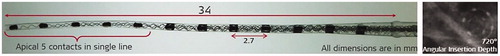
Figure 42. Short electrode array in the range of 13 mm array length along with a CORK type insertion stopper. Image courtesy of MED-EL.
7.8. Reimbursement
Reimbursement is a vital factor in keeping many businesses alive, including MED-EL. Under CMD regulations and based on the operating surgeon’s prescription, the CI device, coupled with special electrodes, may be reimbursed by the healthcare systems in most cases. Successful reimbursement was one of the encouraging aspects for MED-EL to invest time, money and efforts in developing special electrodes as per the request from the operating surgeons.
7.9. Conclusion
Although cochlear anomalies are rare, patients with such conditions shall nevertheless receive optimal treatment, even if it requires additional efforts from both, clinicians and medical device manufacturers. The effectiveness of the overall CI treatment lies in the optimal electrode-neural interface, which is the core reason for MED-EL to go to great lengths in designing special electrodes to match every cochlear condition. Close collaboration with clinicians is the key to innovation in the medical device field, and every special electrode presented in this article is the apparent result of a strong collaboration between clinicians and MED-EL.
The presented special electrode array designs in this article illustrate MED-EL faculty’s diligent and passionate stand towards continuous technological advancements, especially of its CI electrode arrays. It is within the core of the company’s philosophy to address the needs of every patient, be it even of one single, with challenging cochlear conditions. MED-EL makes every effort within its scope to design and produce a special/modified CI device, even if it means exceeding the break-even cost.
MED-EL continues its mission in supporting every single HL patient with special CI devices and expanding its scientific network by creating close collaborations with clinicians. This article is yet another example of the translational science path that MED-EL takes in developing its products; its design concepts are based on unique patient needs first, translated to prototypes, followed by bench testing, and the translational science circle is concluded only with the successful patient outcome.
Acknowledgments
The authors would gratefully like to acknowledge the key contributors to the development of the subject matter. Their contributions are outlined in this article. The authors further acknowledge Claude Jolly from MED-EL for his valuable input and comments during several rounds of review meetings that contributed to the final version of this article.
Disclosure statement
This article is sponsored by MED-EL and has not undergone the regular peer-review process of Acta Oto-Laryngologica. Both the authors are affiliated with MED-EL.
References
- Hochmair-Desoyer I. Technische realisierzng und psychoakustiche evaluation eines systems zur chronischen mehrkanalstimulation des nervus acusticus. Dissertationen Der Technischen Universität Wien. 1979;39.
- Sierra C, Calderón M, Bárcena E, et al. Preservation of residual hearing after cochlear implant surgery with deep insertion electrode arrays. Otol Neurotol. 2019;40(4):e373–e380.
- Erixon E, Hogstorp H, Wadin K, et al. Variational anatomy of the human cochlea: implications for cochlear implantation. Otol Neurotol. 2009;30(1):14.
- Dhanasingh A. Variations in the size and shape of human cochlear malformation types. Anat Rec. 2019;302(10):1792–1799.
- Dhanasingh A, Jolly C. An overview of cochlear implant electrode array designs. Hear Res. 2017;356:93–103.
- Dhanasingh A, Jolly C. Review on cochlear implant electrode array tip fold-over and scalar deviation. J Otol. 2019;14(3):94–100.
- Sennaroğlu L, Bajin MD. Classification and current management of inner ear malformations. Balkan Med J. 2017;34(5):397–411.
- Sun B, Dai P, Zhou C. Study on 2747 cases of inner ear malformation for its classification in patient with sensorineural hearing loss. Lin Chung er Bi Yan Hou Tou Jing Wau Ke Za Zhi. 2015;29:45–47.
- Wang L, Zhang D. Surgical methods and postoperative results of cochlear implantation in 79 cases of ossified cochlea. Acta Otolaryngol. 2014;134(12):1219–1224.
- Bredberg G, Lindström B, Löppönen H, et al. Electrodes for ossified cochleas. Am J Otol. 1997;18(6):S42–S43.
- Bauer PW, Roland PS. Clinical results with the Med-El compressed and split arrays in the United States. Laryngoscope. 2004;114(3):428–433.
- Millar DA, Hillman TA, Shelton C. Implantation of the ossified cochlea: management with the split electrode array. Laryngoscope. 2005;115(12):2155–2160.
- Dejaco D, Prejban D, Fischer N, et al. Successful cochlear implantation of a split electrode array in a patient with far-advanced otosclerosis assisted by electromagnetic navigation: a case report. Otol Neurotol. 2018;39(7):e532–e537.
- https://eur-lex.europa.eu/legal-content/EN/TXT/PDF/?uri=CELEX:31993L0042&from=DE
- Cock E. A contribution to the pathology of congenital deafness. Guys Hosp Rep. 1838;7:289–307.
- Yiin RS, Tang PH, Tan TY. Review of congenital inner ear abnormalities on CT temporal bone. Br J Radiol. 2011;84(1005):859–863.
- Weiss NM, Langner S, Mlynski R, et al. Evaluating common cavity cochlear deformities using CT images and 3D reconstruction. Laryngoscope. 2021;131(2):386–391.
- Beltrame MA, Bonfioli F, Frau GN. Cochlear implant in inner ear malformation: double posterior labyringthotomy approach to common cavity. Adv Otorhinolaryngol. 2005;57:113–119.
- Beltrame MA, Birman CS, Cervera Escario J, et al. Common cavity and custom-made electrodes: speech perception and audiological performance of children with common cavity implanted with a custom-made MED-EL electrode. Int J Pediatr Otorhinolaryngol. 2013;77(8):1237–1243.
- Graham JM, Phelps PD, Michaels L. Congenital malformations of the ear and cochlear implantation in children: review and temporal bone report of common cavity. J Laryngol Otol Suppl. 2000;25:1–14.
- Sennaroğlu L, Atay G, Bajin MD. A new cochlear implant electrode with a “‘cork’-type stopper for inner ear malformations”. Auris Nasus Larynx. 2014;41(4):331–336.
- Polak M, Eshraghi AA, Nehme O, et al. Evaluation of hearing and auditory nerve function by combining ABR, DPOAE and eABR tests into a single recording session. J Neurosci Methods. 2004;134(2):141–149.
- Frohne C, Lesinski A, Battmer RD, et al. Intraoperative test of auditory nerve function. Am J Otol. 1997;18(6):S93–S94.
- Lassaletta L, Polak M, Huesers J, et al. Usefulness of electrical auditory brainstem responses to assess the functionality of the cochlear nerve using an intracochlear test electrode. Otol Neurotol. 2017;38(10):e413–e420.
- Cinar BC, Yarali M, Atay G, et al. The role of eABR with intracochlear test electrode in decision making between cochlear and brainstem implants: preliminary results. Eur Arch Otorhinolaryngol. 2017;274(9):3315–3326.
- https://oto.wustl.edu/history-is-made-restoring-hearing-in-patients-with-acoustic-neuromas/
- Dahm V, Auinger AB, Honeder C, et al. Simultaneous vestibular schwannoma resection and cochlear implantation using electrically evoked auditory brainstem response audiometry for decision-making. Otol Neurotol. 2020;41(9):1266–1273.
- Polterauer D, Neuling M, Müller J, et al. PromBERA: a preoperative eABR: an update. Curr Dir Biomed Eng. 2018;4(1):563–565.
- Plontke SK, Fröhlich L, Cozma S, et al. Hearing rehabilitation after subtotal cochleoectomy using a new, perimodiolar malleable cochlear implant electrode array: a preliminary report. Eur Arch Otorhinolaryngol. 2021;278(2):353–362.