 ?Mathematical formulae have been encoded as MathML and are displayed in this HTML version using MathJax in order to improve their display. Uncheck the box to turn MathJax off. This feature requires Javascript. Click on a formula to zoom.
ABSTRACT
In this work, we consider the method of non-linear boundary integral equation for solving numerically the inverse scattering problem of obliquely incident electromagnetic waves by a penetrable homogeneous cylinder in three dimensions. We consider the indirect method and simple representations for the electric and the magnetic fields in order to derive a system of five integral equations, four on the boundary of the cylinder and one on the unit circle where we measure the far-field pattern of the scattered wave. We solve the system iteratively by linearizing only the far-field equation. Numerical results illustrate the feasibility of the proposed scheme.
1. Introduction
The inverse obstacle scattering problem is to image the scattering object, i.e. find its shape and location, from the knowledge of the far-field pattern of the scattered wave. The medium is illuminated by light at given direction and polarization. Then, Maxwell’s equations are used to model the propagation of the light through the medium, see [Citation1,Citation2] for an overview. This problem is of great interest because of its applications in many areas of physics and engineering (non-destructive testing, biomedical imaging, remote sensing, and target identification). We refer to [Citation3–Citation7] for some recent applications.
Due to the complexity of the combined system of equations for the electric and the magnetic fields, it is common to impose additional assumptions on the incident illumination and the nature of the scatterer. We consider time-harmonic incident electromagnetic plane wave that due to the linearity of the problem will result to a time-independent system of equations. In addition, the penetrable object is considered as an infinitely long homogeneous cylinder. Then, it is characterized by constant permittivity and permeability. The problem is further simplified if we impose normal incidence for the incident wave. However, in this work, we consider the more complicated case of oblique incidence.
The three-dimensional scattering problem modeled by Maxwell’s equations is then equivalent to a pair of two-dimensional Helmholtz equations for two scalar fields (the third components of the electric and the magnetic fields). This approach reduces the difficulty of the problem but results to more complicated boundary conditions. The transmission conditions now contain also the tangential derivatives of the electric and magnetic fields. In [Citation8], we showed that the corresponding direct problem is well-posed and we constructed a unique solution using the direct integral equation method. A similar problem has been considered for an impedance cylinder embedded in a homogeneous [Citation9] and in an inhomogeneous medium [Citation10]. Different numerical solutions of the direct problem have been also proposed using finite difference/element methods [Citation11,Citation12], the Galerkin method [Citation13], the Nyström method [Citation14], the Green’s tensor method [Citation15], the method of auxiliary sources [Citation16,Citation17], the generalized Debye method [Citation18], and the separation of variables method [Citation19–Citation21].
On the other hand, the inverse problem is non-linear and ill-posed. The non-linearity is due to the dependence of the solution of the scattering problem on the unknown boundary curve. The smoothness of the mapping from the boundary to the far-field pattern reflects the ill-posedness of the inverse problem. The unique solvability of the inverse problem is still an open problem. The first and only, to our knowledge, uniqueness result was presented recently in [Citation22] for the case of an impedance cylinder using the Lax–Phillips method.
In this work, we solve the inverse problem by formulating an equivalent system of non-linear integral equations that is solved using a regularized iterative scheme. This method was introduced by Kress and Rundell [Citation23] and then considered in many different problems, in acoustic scattering problems [Citation24,Citation25], in elasticity [Citation26,Citation27] and in electrical impedance problem [Citation28]. Our iterative scheme is based on the idea of Johansson and Sleeman [Citation29] first applied to the inverse acoustic scattering problem for a sound soft object. See [Citation26,Citation30], for applications of the method in different problems. We assume integral representations for the solutions that result to a system consisting of four integral equations on the unknown boundary (considering the transmission conditions) and one on the unit circle (taking into account the asymptotic expansion of the solutions). In our case, compared to [Citation29,Citation30] where only smooth and weakly singular integral operators are present in the systems of equations, appears also a singular operator (the tangential derivative of the single layer) due to the much more involved transmission conditions.
We solve the system of equations in two steps. First, given an initial guess for the boundary curve, we solve the well-posed subsystem (equations on the boundary) to obtain the corresponding densities and then we solve the linearized (with respect to the boundary) ill-posed far-field equation to update the initial approximation of the radial function. We consider Tikhonov regularization and the normal equations are solved by the conjugate gradient method. To improve the reconstructions, we take also into account measurements for few incident waves.
This work can be seen as a first step for solving the problem in the more complicated anisotropic case. There, one has to treat the three-dimensional problem differently and the integral equation method will result to a more complicated system of equations. The simplification due to the symmetry of the problem is also questionable and the unique solvability even for the direct problem is still an open problem. We refer to [Citation31] for a numerical solution using a subspace-based optimization method.
The paper is organized as follows: in Section 2, we present the direct scattering problem, the elastic potentials, and the equivalent system of integral equations that provide us with the far-field data. The inverse problem is stated in Section 3, where we construct an equivalent system of integral equation using the indirect integral equation method. In Section 4, the two-step method for the parametrized form of the system and the necessary Fréchet derivative of the integral operators are presented. The numerical examples give satisfactory results and justify the applicability of the proposed iterative scheme.
2. The direct problem
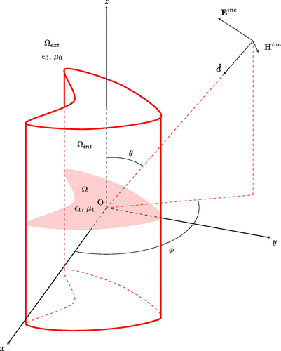
We consider the scattering of an electromagnetic wave by a penetrable cylinder in . Let
We denote by
the cylinder, where
is a bounded domain in
with smooth boundary
The cylinder
is oriented parallel to the z-axis and
is its horizontal cross section. We assume constant permittivity
and permeability
for the exterior domain
The interior domain
is also characterized by constant parameters
and
We define the exterior magnetic and electric field
for
and the interior fields
and
for
that satisfy the Maxwell’s equations
(1)
(1)
and the transmission conditions(2)
(2)
where is the outward normal vector, directed into
.
We illuminate the cylinder with an incident electromagnetic plane wave at oblique incidence, meaning transverse magnetic (TM) polarized wave. We define by the incident angle with respect to the negative z axis and by
the polar angle of the incident direction
(in spherical coordinates), see Figure . Then,
and the polarization vector is given by
satisfying
for
The upcoming analysis can also be carried out to the case of transverse electric polarized incident plane wave.
In the following, due to the linearity of the problem, we suppress the time-dependence of the fields and because of the cylindrical symmetry of the medium we express the incident fields as separable functions of and z.
Let be the frequency and
the wave number in
. We define
and
and it follows that the incident fields can be decomposed to [Citation8]
(3)
(3)
where
After some calculations, we can reformulate Maxwell’s euqations (Equation1(1)
(1) ) as a system of equations only for the z-component of the electric and magnetic fields [Citation8]. The interior fields
and
and the exterior fields
and
satisfy the Helmholtz equations
(4)
(4)
where Here, we assume
in order to have
The transmission conditions (Equation2(2)
(2) ) can also be written only for the z-component of the fields. Let
be a local coordinate system, where
is the outward normal vector and
the outward tangent vector on
We define
where
and
denote the unit vectors in
Then, we rewrite the boundary conditions as [Citation8]
(5)
(5)
where for
The exterior fields are decomposed to
and
where
and
denote the scattered electric and magnetic field, respectively. From (Equation3
(3)
(3) ), we see that
(6)
(6)
To ensure that the scattered fields are outgoing, we impose in addition the radiation conditions in
(7)
(7)
where uniformly over all directions.
Now we are in position to formulate the direct transmission problem for oblique incident wave: find the fields , and
that satisfy the Helmholtz equations (Equation4
(4)
(4) ), the transmission conditions (Equation5
(5)
(5) ) and the radiation conditions (Equation7
(7)
(7) ).
Theorem 2.1:
If is not an interior Dirichlet eigenvalue and
is not an interior Dirichlet and Neumann eigenvalue, then the direct transmission problem (Equation4
(4)
(4) )–(Equation7
(7)
(7) ) admits a unique solution.
Proof The proof is based on the integral representation of the solution resulting to a Fredholm type system of boundary integral equations. For more details, see [Citation8, Theorem 3.2].
In the following, counts for the exterior (
) and interior domain (
), respectively. We introduce the single- and double-layer potentials defined by:
(8)
(8)
where is the fundamental solution of the Helmholtz equation in
(9)
(9)
and is the Hankel function of the first kind and zero order. We define also the integral operators
(10)
(10)
The following theorem was proven in [Citation8].
Theorem 2.2:
Let the assumptions of Theorem 2.1 still hold. Then, the potentials(11)
(11)
solve the direct transmission problem (Equation4(4)
(4) )–(Equation7
(7)
(7) ) provided that the densities
and
satisfy the system of integral equations
(12)
(12)
where
and The rest of the densities satisfy
and
The solutions and
of (Equation4
(4)
(4) )–(Equation7
(7)
(7) ) have the asymptotic behavior
(13)
(13)
where The pair
is called the far-field pattern corresponding to the scattering problem (Equation4
(4)
(4) )–(Equation7
(7)
(7) ). Its knowledge is essential for the inverse problem and using (Equation11
(11)
(11) ) we can compute it by:
(14)
(14)
where is the unit ball. The far-field operators are given by:
(15)
(15)
where is the far-field of the Green function
given by:
3. The inverse problem
The inverse scattering problem, we address here, reads: find the shape and the position of the inclusion meaning reconstruct its boundary
, given the far-field patterns
for all
for one or few incident fields (Equation6
(6)
(6) ).
3.1. The integral equation method
To solve the inverse problem we apply the method of non-linear boundary integral equations, which in our case, results to a system of four integral equations on the unknown boundary and one on the unit circle where the far-field data are defined. This method was first introduced in [Citation23] and further considered in various inverse problems, see for instance, [Citation25,Citation27,Citation32,Citation33]. Since the direct problem was solved with the direct method (Green’s formulas), in order to obtain our numerical data, here we adopt a different approach based on the indirect integral equation method, using simple representations for the fields.
We assume a double-layer representation for the interior fields and a single-layer representation for the exterior fields. Thus, we set(16)
(16)
Substituting the above representations in the transmission conditions (Equation5(5)
(5) ) and considering the well-known jump relations, we get the system of integral equations on
(17)
(17)
In addition, given the far-field operators (Equation15(15)
(15) ) and the representations (Equation16
(16)
(16) ) of the exterior fields, we see that the unknown boundary
and the densities
and
satisfy also the far-field equations
(18a)
(18a)
(18b)
(18b) where the right-hand sides are the known far-field patterns from the direct problem. The Equation (Equation17
(17)
(17) ) in matrix form reads
(19)
(19)
where
The matrix due to its special form and the boundness of
has a bounded inverse given by:
(20)
(20)
Then, Equation (Equation19(19)
(19) ) takes the form
(21)
(21)
where now is the identity matrix and
Using the mapping properties of the integral operators [Citation34], we see that the operator is compact.
We observe that we have six equations (Equation21(21)
(21) ) and () for the five unknowns:
and the four densities. Thus, we consider the linear combination
(Equation18a
(18a)
(18a) ) +
(Equation18b
(18b)
(18b) ) as a replacement for the far-field equations in order to state the following theorem as a formulation of the inverse problem.
Theorem 3.1:
Given the incident field (Equation6(6)
(6) ) and the far-field patterns
for all
if the boundary
and the densities
and
satisfy the system of equations
(22a)
(22a)
(22b)
(22b)
(22c)
(22c)
(22d)
(22d)
(22e)
(22e) then,
solves the inverse problem.
The integral operators in () are linear with respect to the densities but non-linear with respect to the unknown boundary The smoothness of the kernels in the far-field Equation (Equation22e
(22e)
(22e) ) reflects the ill-posedness of the inverse problem.
To solve the above system of equations, we consider the method first introduced in [Citation29] and then applied in different problems, see for instance [Citation26,Citation30,Citation35]. More precisely, given an initial approximation for the boundary , we solve the subsystem (Equation22a
(22a)
(22a) )–(Equation22d
(22d)
(22d) ) for the densities
and
Then, keeping the densities
and
fixed we linearize the far-field Equation (Equation22e
(22e)
(22e) ) with respect to the boundary. The linearized equation is solved to obtain the update for the boundary. The linearization is performed using Fréchet derivatives of the operators and we also regularize the ill-posed last equation.
To present the proposed method in detail, we consider the following parametrization for the boundary
where is a
-smooth,
-periodic, injective in
meaning that
for all
The non-negative function r represents the radial distance of
from the origin. Then, we define
and the parametrized form of () is given by:(23)
(23)
with the parametrized operators
and the right-hand side
In addition, we set The matrix
denotes the discretized kernel of the operator
The explicit forms of the kernels can be found for example, in [Citation8, Equation 4.3]. The operators
act on the densities and the first variable r shows the dependence on the unknown parametrization of the boundary. Only
is independent of the radial function.
Let the function q stand for the radial function of the perturbed boundary
Then the iterative method reads:
Iterative Scheme 1:
Let be an initial approximation of the radial function. Then, in the kth iteration step:
| (i) | We assume that we know | ||||
| (ii) | Keeping the densities | ||||
Remark 1:
In order to take advantage of the available measurement data, we can also keep the overdetermined system (Equation17(17)
(17) ) and () instead of (Equation22e
(22e)
(22e) ) and replace Equation (Equation25
(25)
(25) ) with
(26)
(26)
where now and
The Fréchet derivatives of the operators are calculated by formally differentiating their kernels with respect to r (27)
(27)
Recall that If
is not an interior Neumann eigenvalue, then the operator
is injective [Citation25]. Using similar arguments as in [Citation30,Citation36], we can relate the above iterative scheme to the classical Newton’s method.
The iterative scheme 3.1 can also be generalized to the case of multiple illuminations
Iterative Scheme 2:
[Multiple illuminations] Let be an initial approximation of the radial function. Then, in the kth iteration step:
| (i) | We assume that we know | ||||
| (ii) | Then, keeping the densities fixed, we solve the overdetermined version of the linearized fifth equation of (Equation23 | ||||
4. Numerical implementation
In this section, we present numerical examples that illustrate the applicability of the proposed method. We use quadrature rules for integrating the singularities considering trigonometric interpolation. The convergence and error analysis are given in [Citation37,Citation38]. Then, the system of integral equations is solved using the Nyström method. The parametrized forms of the integral operators are presented in [Citation8, Section 4]. We approximate the smooth kernels with the trapezoidal rule and the singular ones with the well-known quadratures rules [Citation38].
In the following examples, we consider two different boundary curves. A peanut-shaped and an apple-shaped boundary with radial function
and
respectively.
To avoid an inverse crime, we construct the simulated far-field data using the numerical scheme (Equation12(12)
(12) ) and considering double amount of quadrature points compared to the inverse problem. We approximate the radial function q by a trigonometric polynomial of the form
and we consider 2n equidistant points The well-posed subsystem (Equation24
(24)
(24) ) does not require any special treatment. The ill-posed linearized far-field Equation (Equation25
(25)
(25) ) is solved by Tikhonov regularization. We rewrite (Equation25
(25)
(25) ) as:
(29)
(29)
for and we decompose (Equation27
(27)
(27) ) as:
(30)
(30)
where
We replace the derivative of q by the derivative of the trigonometric interpolation polynomial
with weight
Then, at the kth step we minimize the Tikhonov functional of the discretized equation
where is the vector with the unknowns coefficients
of the radial function, and
are given by:
for The multiplication matrix
stands for the trigonometric functions of the approximated radial function and is given by:
Here, defines the corresponding Sobolev norm. Since q is real valued, we solve the following regularized equation:
(31)
(31)
on the kth step, where the matrix corresponds to the Sobolev
penalty term. We solve (Equation31
(31)
(31) ) using the conjugate gradient method. We update the regularization parameter in each iteration step k by:
for some given initial parameter To test the stability of the iterative method against noisy data, we add also noise to the far-field patterns with respect to the
norm
for some given noise levels, where
for
normally distributed random variables.
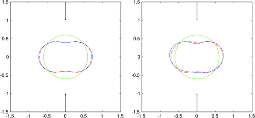
Figure 2. Reconstruction of a peanut-shaped boundary for two incident fields, frequency for exact data (left) and data with
noise (right).
Already in simpler cases [Citation30], the knowledge of the far-field patterns for one incident wave is not enough to produce satisfactory reconstructions. Thus, we will also use multiple incident directions. To do so, we have to consider different values of the polar angle since in
as we see from (Equation6
(6)
(6) ), corresponds to the incident direction
. We set
4.1. Numerical results
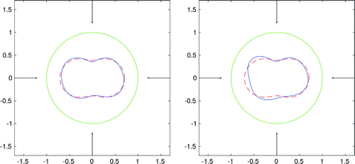
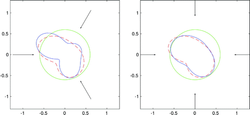
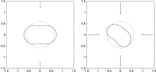
We present reconstructions for different boundary curves, different number of incident directions and initial guesses for exact and perturbed far-field data. In all figures the initial guess is a circle with radius a green solid line, the exact curve is represented by a dashed red line and the reconstructed by a solid blue line. The arrows denote the directions of the incoming incident fields.
We use collocation points for the direct problem and
for the inverse. In the first five examples, we set the exterior parameters
and the interior
We set
and
as the initial regularization parameter.
Figure 3. Reconstruction of a peanut-shaped boundary for four incident fields, frequency noisy data (
noise), with initial guess
(left) and
(right).
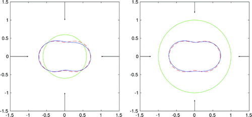
Figure 4. Reconstruction of a peanut-shaped boundary for four incident fields, coefficients, frequency
for exact data (left) and data with
noise (right).
In the first three examples, we consider the peanut-shaped boundary. In the first example, the regularized Equation (Equation31(31)
(31) ) is solved with
penalty term, meaning
and
coefficients. We solve Equation (Equation26
(26)
(26) ) for different incident directions. The reconstructions for
and
are presented in Figure for two incident fields with directions
On the left picture, we see the reconstructed curve for exact data and 9 iterations and on the right picture for noisy data with
and 14 iterations. In the second example, we consider Equation (Equation25
(25)
(25) ), four incident fields, noisy data
and we keep all the parameters as before. The reconstructions for
and 14 iterations are shown in the left picture of Figure , and for
and 20 iterations in the right one. We set
and
(
penalty term) in the third example. The results for
and four incident fields are shown in Figure . Here,
and we use Equation (Equation26
(26)
(26) ). We need 26 iterations for the exact data and 30 iterations for the noisy data (
).
Figure 5. Reconstruction of an apple-shaped boundary for four incident fields, frequency exact data, with initial guess
(left) and
(right).
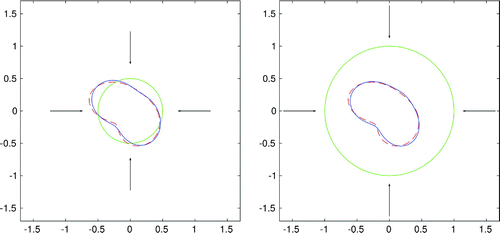
Figure 6. Reconstruction of an apple-shaped boundary for four incident fields, frequency data with
noise, for three (left) and four (right) incident fields.
In the next two examples we consider the apple-shaped boundary, penalty term,
and
coefficients. In the fourth example, we consider Equation (Equation25
(25)
(25) ), noise-free data and four incident fields in order to examine the dependence of the iterative scheme on the initial radial guess. On the left picture of Figure , we see the reconstructed curve for
after 13 iterations and on the right picture for
after 20 iterations. In the fifth example, we consider
noise and
Figure shows the improvement of the reconstruction for more incident fields. On the left picture we see the results for three incident fields, Equation (Equation26
(26)
(26) ) and seven iterations and the reconstructed curve for four incident fields, Equation (Equation25
(25)
(25) ) and 15 iterations is shown on the right picture.
In the last example we consider an electrically larger object, meaning we set and
resulting to a seven times larger (electrically) scatterer compared to the previous examples. We choose
such that the condition
is satisfied. To account also for different oblique directions we set
For
and data with
noise, we present the reconstructions in Figure . We consider for both boundary curves the same initial guess
The results on the left picture are for two incident fields, considering Equation (Equation26
(26)
(26) ) and 35 iterations. On the right picture we present the reconstruction for four incident fields, Equation (Equation25
(25)
(25) ) and 13 iterations.
Figure 7. Reconstruction of a peanut-shaped boundary for two incident fields (left) and an apple-shaped boundary for four incident fields (right). Here, we use and data with
noise.
To conclude, our examples have shown the feasibility of the proposed iterative scheme and the stability against noisy data. However, this method can only be applied to objects with smooth boundaries. In addition, the proposed method performs poorly for only one incident field which is the case also in the acoustic regime. The main reason is that we miss information since we linearize only the far-field equation. Thus, we had to consider few incident illuminations which improve considerably the reconstructions. The initial guess plays also an important role in this scheme.
Notes
No potential conflict of interest was reported by the authors.
References
- Colton D , Kress R . Integral equation methods in scattering theory, Classics in applied mathematics. Philadelphia (PA): SIAM; 2013.
- Colton D , Kress R . Inverse acoustic and electromagnetic scattering theory. 3rd ed. Vol. 93. Applied mathematical sciences. New York (NY): Springer-Verlag; 2013.
- Caorsi S , Donelli M , Franceschini D , et al . A new methodology based on an iterative multiscaling for microwave imaging. IEEE Trans Microwave Theory Tech. 2003;51(4):1162–1173.
- Caorsi S , Massa A , Pastorino M , et al . Detection of buried inhomogeneous elliptic cylinders by a memetic algorithm. IEEE Trans Antennas Propag. 2003;51(10):2878–2884.
- Massa A , Pastorino M , Randazzo A . Reconstruction of two-dimensional buried objects by a differential evolution method. Inverse Prob. 2004;20(6):S135–S150.
- Meng Q , Xu K , Shen F , et al . Microwave imaging under oblique illumination. Sensors. 2016;16(7):1046.
- Oliveri G , Lizzi L , Pastorino M , et al . A nested multi-scaling inexact-Newton iterative approach for microwave imaging. IEEE Trans Antennas Propag. 2012;60(2):971–983.
- Gintides D , Mindrinos L . The direct scattering problem of obliquely incident electromagnetic waves by a penetrable homogeneous cylinder. J. Integral Equ Appl. 2016;28(1):91–122.
- Wang H , Nakamura G . The integral equation method for electromagnetic scattering problem at oblique incidence. Appl Numer Math. 2012;62:860–873.
- Nakamura G , Wang H . The direct electromagnetic scattering problem from an imperfectly conducting cylinder at oblique incidence. J Math Anal Appl. 2013;397:142–155.
- Cangellaris AC , Lee R . Finite element analysis of electromagnetic scattering from inhomogeneous cylinders at oblique incidence. IEEE Trans Antennas Propag. 1991;39:645–650.
- Yan J , Gordon RK , Kishk AA . Electromagnetic scattering from impedance elliptic cylinders using finite difference method (oblique incidence). Electromagnetics. 1995;15(2):157–173.
- Lucido M , Panariello G , Schettiho F . Scattering by polygonal cross-section dielectric cylinders at oblique incidence. IEEE Trans Antennas Propag. 2010;58:540–551.
- Tsalamengas JL . Exponentially converging Nyström methods applied to the integral-integrodifferential equations of oblique scattering / hybrid wave propagation in presence of composite dielectric cylinders of arbitrary cross section. IEEE Trans Antennas Propag. 2007;55(11):3239–3250.
- Martin OJF , Piller NB . Electromagnetic scattering in polarizable backgrounds. Phys Rev E. 1998;58(3):3909–3915.
- Tsitsas NL , Alivizatos EG , Anastassiu HT , et al . Optimization of the method of auxiliary sources (MAS) for scattering by an infinite cylinder under oblique incidence. Electromagnetics. 2005;25(1):39–54.
- Tsitsas NL , Alivizatos EG , Anastassiu HT , et al . Optimization of the method of auxiliary sources (MAS) for oblique incidence scattering by an infinite dielectric cylinder. Electr Eng. 2007;89:353–361.
- Li R , Han X , Ren KF . Generalized Debye series expansion of electromagnetic plane wave scattering by an infinite multilayered cylinder at oblique incidence. Phys Rev E. 2009;79(3):036602.
- Mao SC , Wu ZS , Li HY . Three-dimensional scattering by an infinite homogeneous anisotropic elliptic cylinder in terms of Mathieu functions. J Opt Soc Am A. 2009;26:2282–2291.
- Zouros GP . Electromagnetic plane wave scattering by arbitrarily oriented elliptical dielectric cylinders. J Opt Soc Am A. 2011;28(11):2376–2384.
- Zouros GP . Oblique electromagnetic scattering from lossless or lossy composite elliptical dielectric cylinders. J Opt Soc Am. 2013;30(2):196–205.
- Nakamura G , Sleeman BD , Wang H . On uniqueness of an inverse problem in electromagnetic obstacle scattering for an impedance cylinder. Inverse Prob. 2012;28(5):055012.
- Kress R , Rundell W . Nonlinear integral equations and the iterative solution for an inverse boundary value problem. Inverse Prob. 2005;21:1207–1223.
- Ivanyshyn O , Johansson BT . Nonlinear integral equation methods for the reconstruction of an acoustically sound-soft obstacle. J Integral Equ Appl. 2007;19(3):289–308.
- Ivanyshyn O , Johansson BT . Boundary integral equations for acoustical inverse sound-soft scattering. J Inverse Ill-posed Prob. 2008;16(1):65–78.
- Chapko R , Gintides D , Mindrinos L . The inverse scattering problem by an elastic inclusion. Adv Comput Math. 2017.
- Gintides D , Midrinos L . Inverse scattering problem for a rigid scatterer or a cavity in elastodynamics. ZAMM Z Angew Math Mech. 2011;91(4):276–287.
- Eckel H , Kress R . Nonlinear integral equations for the inverse electrical impedance problem. Inverse Prob. 2007;23(2):475.
- Johansson BT , Sleeman BD . Reconstruction of an acoustically sound-soft obstacle from one incident field and the far-field pattern. IMA J Appl Math. 2007;72:96–112.
- Altundag A , Kress R . On a two-dimensional inverse scattering problem for a dielectric. Appl Anal. 2012;91(4):757–771.
- Agarwal K , Pan L , Chen X . Subspace-based optimization method for reconstruction of 2-D complex anisotropic dielectric objects. IEEE Trans Microwave Theory Tech. 2010;58(4):1065–1074.
- Cakoni F , Kress R . Integral equations for inverse problems in corrosion detection from partial cauchy data. Inverse Prob Imaging. 2007;1(2):229–245.
- Cakoni F , Kress R , Schuft C . Integral equations for shape and impedance reconstruction in corrosion detection. Inverse Prob. 2010;26:095012.
- Kress R . Linear integral equations. 3rd ed. New York (NY): Springer; 2014.
- Lee KM . Inverse scattering problem from an impedance crack via a composite method. Wave Motion. 2015;56:43–51.
- Hohage T , Schormann C . A Newton-type method for a transmission problem in inverse scattering. Inverse Prob. 1998;14(5):1207.
- Kress R . On the numerical solution of a hypersingular integral equation in scattering theory. J Comput Appl Math. 1995;61(3):345–360.
- Kress R . A collocation method for a hypersingular boundary integral equation via trigonometric differentiation. J Integral Equ Appl. 2014;26(2):197–213.

