
 ?Mathematical formulae have been encoded as MathML and are displayed in this HTML version using MathJax in order to improve their display. Uncheck the box to turn MathJax off. This feature requires Javascript. Click on a formula to zoom.
Abstract
This paper presented an analytical and closed-form solution for the harmonic contents that were injected in the five-level inverters from asymmetrical DC sources or batteries which were suitable for renewable energy sources. In the five-level inverters, two DC sources V1 and V2 were used to synthesize the output voltage. Therefore, two transcendental equations were formulated for the fundamental and the third harmonic orders based on the unequal DC sources V1 and V2. These transcendental equations were solved analytically for low switching control technique. The proposed solution included the modulation index change which resulted in changing the fundamental component. Therefore, two switching angles are formulated and solved analytically to control the amplitude of the fundamental voltage and cancel the third order harmonic. A well-known third order equation was generated. Thus, a closed-form solution for the above two switching angles will be generated in terms of the modulation index. The proposed solution was tested for a wide range of V1/V2 ratio. Some selected simulation and experimental results were provided to validate the proposed method for wide ranges of both modulation index and V1/V2 ratio.
1. Introduction
Multilevel inverters (MLIs) [Citation1–4] are preferred compared to the conventional two-level H-bridge inverter for many reasons. MLIs are able to process high power at a low switching frequency, low switching frequency is an integer multiple of the fundamental frequency [Citation5,Citation6], and high output voltage resolution (low total harmonic distortion (THD)). Therefore MLIs have lower switches stresses with higher efficiency. One more important advantage of the MLIs is the modularity which enables MLIs to operate even if under faulty condition [Citation7,Citation8]. This can be done by modifying the control algorithm to bypass the faulty section without changing the MLI structure. There are three main MLIs categories (1) neutral point clamped MLI; (2) cascaded DC source inverter, (3) flying capacitor MLI inverter. MLIs can be divided into two main categories based on the DC sources available, symmetrical and asymmetrical MLIs. In symmetrical MLI, all DC sources are equal while in asymmetrical MLIs DC sources are not equal. The most common ratio among DC sources is 1:2 and 1:3. It can be noted that the 1:3 ratio can develop the highest output voltage resolution and thus lowest THD. Recently, hybrid MLI was introduced [Citation9–12] to reduce the number of switches used and thus increase their reliability. In this MLI type different structure with different DC sources ratio.
Lower order harmonics have the highest impact on the THD and the FFT analysis in the case of low switching frequency [Citation5,Citation6], thus they need to be removed. Either symmetrical or asymmetrical DC sources can be used for the MLI. However, MLI based asymmetrical DC sources are the most general and practical case as it generates a higher number of levels and so lower THD. In low switching control scheme, selective harmonic elimination (SHE) [Citation13–15] technique is well-known in success to cancel lower order harmonics. A set of nonlinear equations is formulated to meet the targeted objective functions. Therefore, many articles solved these harmonic equations of the MLI using different algorithms. Some of these attempts use the well-known Newton Raphson technique, the theory of symmetric polynomials, genetic algorithms (GA) and artificial neural network (ANN) [Citation16–20]. In these techniques, the solution of harmonic equations is done in the offline state using a computer, and then the solution of switching angles is stored in a lookup table which leads to low-resolution results. Also, the solution can be carried out in real time, but the solution is very complicated with a discontinuous range solution over the full modulation index range.
Other solutions are proposed in [Citation21,Citation22]. A simple closed-form analytical solution is proposed in [Citation21] which is fast, accurate and it can guarantee harmonic cancellation as stipulated. Also in [Citation22], a real-time solution was done using classical proportional–integral (PI) control. Both solutions proposed in [Citation21,Citation22] are limited only for MLI using symmetrical DC sources which is not the practical case. Therefore, this letter extends the solution proposed in [Citation21] for MLI using asymmetrical DC sources. It is worth to note that asymmetrical DC sources can be resulted from designing different input DC sources with arbitrary functions or due to mismatch usually introduced by renewable energy sources due to environmental conditions such as partial shadow in Photovoltaic case [Citation22].
2. Proposed system model
In this case study, the Fourier transforms for the well-known two switching angles waveform shown in Figure (b,c) respectively are given below:
(1)
(1)
(2)
(2)
(3)
(3) where mi is the modulation index and
is the fundamental amplitude.
Figure 1. (a) Asymmetric cascaded single-phase inverter; (b) output waveform at low mi; (c) output waveform at high mi with V1 ≠ V2.
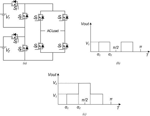
It is worth noting that for the low modulation index (mi) as in (3), only a single DC V1 source is utilized to generate a three-level inverter waveform as shown in Figure (a). Thus, there is no meaning for symmetrical or asymmetrical DC sources and solution of this system of (1) is given in [Citation21]. In addition, when higher h1 required, both DC sources V1 and V2 must be used, and the solution of (2) for symmetrical DC sources; i.e. V1 = V2 = Vdc, is also given in [Citation21]. However, such a solution becomes inapplicable when V1 and V2 are not equal, as shown in Figure (b). Therefore, the target of this case study is to find a closed-form solution for the system defined by (2). The solution presented and
that can fix the fundamental output voltage component and at the same time, it can cancel the lowest order harmonic, which is the third order harmonic. This can be driven from (2) and (3) as follow:
(4)
(4)
(5)
(5)
where
Using the cosine of the triple angle identity: . Then the third harmonic Equation (5) can be manipulated to become:
(6)
(6)
(7)
(7)
From (6), can be expressed in terms of
(8)
(8)
Substituting (8) into (7) results in
(9)
(9)
This equation can be rearranged as follows:
(10)
(10)
(11)
(11)
where
.
By solving (11), can be found, then can be calculated from (8). Equation (11) gives a closed-form expression in a third order polynomial, which can be solved directly by any digital controller. It calculates the optimum switching angles at high mi over a mismatch between V1 and V2. Figure illustrates the area where the solutions are feasible. It could be noticed that the proposed solutions depend on two main factors, they are which varies from 0.6 to 1.1 and ratio of
which varies from 0.6 to 1.7. The resulted solutions are switching angles and
, which varies from . By noticing Figure , it can be concluded that the proposed solution is valid for almost the whole ranges of
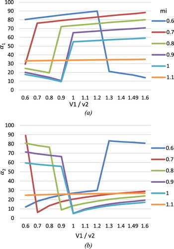
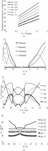
except very low scattered points (the white spot points in the curve). This is attributed to the solution at these white spot points do not satisfy ranges of switching angles. A representation of the areas where a satisfying solution exists is done by plotting percentage between V1/V2 and modulation index mi. The solution is almost continuous for V1/V2 range from 0.6 to 1.6. Note that for mi less than 0.5, the system is not 5-level and so there is no meaning for solving it. Figure (a,b) shows the different values of θ1 and θ2 respectively, based on the solution of (10) versus V1/V2 ratio at different mi, within the area defined by the rectangle in Figure .
Figure 2. Modulation index () versus the ratio
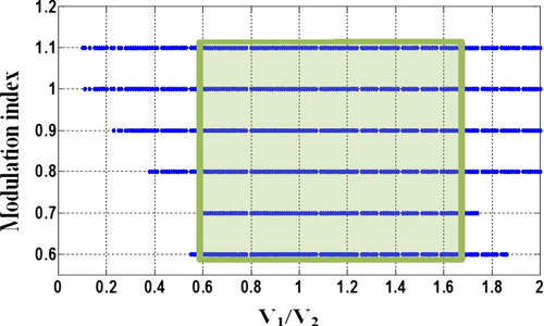
Figure 3. For mi = 0.6 to 1.1, (a) versus
(b)
versus
3. Simulation results
A MATLAB/SIMULINK model has been built to check the validity of the proposed solution. The model is based on a single-phase cascaded full bridge multilevel inverter as shown in Figure (a). Figure shows the block diagram of the MATLAB/SIMULINK model, its gating signals are generated by a proposed solution that finds the optimal switching angles α1 and α2 to eliminate the third harmonic component, taking into consideration values V1, V2 and modulation index mi. Two unequal DC sources V1 and V2 are connected to the inverter with ratio of V1/ V2. Both inverter’s modulation index mi and DC voltage ratio can be changed. Based on the aforementioned analyses, mi can be changed from 0.6 to 1.1 while DC voltage sources ratio can be changed from 0.6 to 1.6. Three different cases have been selected to show and represent the proposed analyses. Figures show these three different cases. Each figure includes output voltage time response and its harmonic spectrum. It is obvious that the third harmonic is cancelled in these three cases, in addition to; multiples of the third harmonics are cancelled too in some cases especially for mi around 1.
Figure 4. System block diagram.
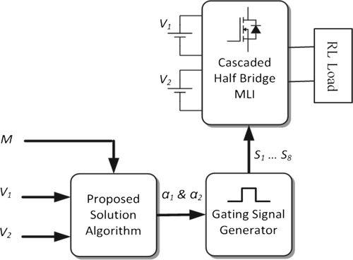
Figure 5. (a) Output voltage for V1 = 10.8 V, V2 = 18 V, V1/V2 = 0.6, mi = 0.7, α1 = 29.48° and α2 = 89.13°, (b) output voltage spectrum.
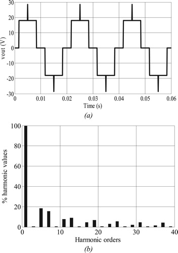
Figure 6. (a) Output voltage for V1 = 16.2 V, V2 = 18 V, V1/V2 = 0.9, mi = 0.9, α1 = 10.61° and α2 = 66.41°, (b) output voltage spectrum.
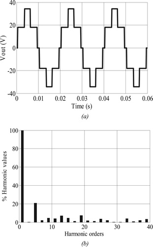
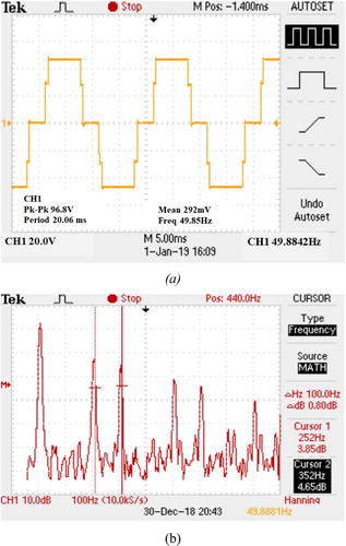
Figure 7. (a) Output voltage for V1 = 28.8 V, V2 = 18 V, V1/V2 = 1.6, mi = 1.1, α1 = 26.94° and α2 = 34.92°, (b) output voltage spectrum.
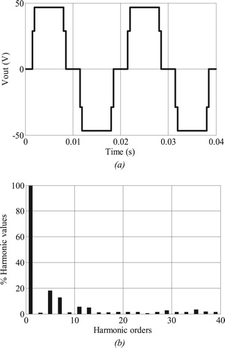
Figure (a–d) shows the absolute values for the fundamental voltage component and the harmonic contents for the fundamental frequency 50 Hz versus DC voltage ratio at V1 = 18 V for a wide range of modulation index. It proves the validity of the proposed solution by successfully eliminating the third harmonic content at every modulation index step change. Around modulation index equals 1, the third harmonic and its multiple are vanished leads to lower THD as shown in Figure (d).
Figure 8. Harmonic analyses versus V1/V2 ratio for V1 = 18 V; (a) Value of fundamental component; (b) Values of third harmonic component and its multiples; (c) Other lower harmonic components. (d) THD versus V1/V2 ratio for different values of modulation index.
Therefore, it is clear from the simulation results that the proposed solution outcomes matched with the theoretical analysis expectations within the predefined range of DC sources mismatch ratio V1/V2 versus different values of modulation index mi.
4. Experimental results
A small inverter prototype was built to experimentally prove the validity of the proposed analyses with the same circuit and model that was used in the simulation. It consists of 2 regular DC power supplies, 8 power MOSFET switches IRF740 and microcontroller PIC16F917.
In order to validate the proposed solution and its simulation results, similar test cases were applied to the experiment setup as shown in Figures , they show the inverter’s output waveforms and its harmonic spectrums for the three cases similar to simulation results. It can be noticed that the third harmonic is vanished in these figures as stipulated in the aforementioned analysis.
Figure 9. (a) Output voltage for V1 = 10.8 V, V2 = 18 V, V1/V2 = 0.6, mi = 0.7, α1 = 29.48 and α2 = 89.13°, (b) output voltage spectrum where cursor X1 at 250 Hz and cursor X2 at 350 Hz.
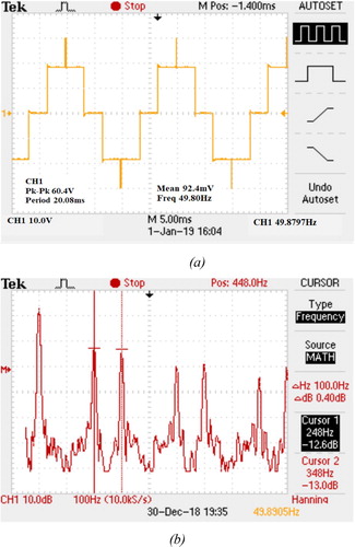
Figure 10. (a) Output voltage for V1 = 16.2 V, V2 = 18 V, V1/V2 = 0.9, mi = 0.9, α1 = 10.61° and α2 = 66.41°, (b) output voltage spectrum where cursor X1 at 250 Hz and cursor X2 at 450 Hz.
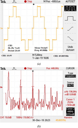
Figure 11. (a) Output voltage for V1 = 28.8 V, V2 = 18 V, V1/V2 = 1.6, mi = 1.1, α1 = 26.94° and α2 = 34.92o, (b) output voltage spectrum where cursor X1 at 250 Hz and cursor X2 at 350 Hz.
In each case, the harmonic spectrum proves the validity of the proposed solution to eliminate the third harmonic component in single-phase five-level inverter. The proposed solution produces values of switching angles (αi) in corresponding to input DC voltage mismatch and targeted modulation index.
5. Conclusions
For asymmetrical cascaded single-phase, five-level inverter, a low switching control scheme employing SHE technique was successfully done. The provided solution was simple and it was a closed-form analytical solution type. The proposed solution was generated from a third order equation which has a well-known solution. The main idea was that the harmonic equations have been solved after replacing the cos(nα) to its cos(α), then a mathematical processing was done to form the third order equation in a single variable. The proposed solution modulation index (mi) range was found to be wide which was from mi = 0.6 to 1.1. Noting that for lower mi range less than 0.6 there was no meaning for asymmetrical DC sources where single DC source was used. The selected simulation and experimental results were well matched with the analytical provided which proved the proposed idea.
Disclosure statement
No potential conflict of interest was reported by the authors.
ORCID
Mahrous Ahmed http://orcid.org/0000-0002-8855-3739
Mohamed Orabi http://orcid.org/0000-0002-2433-9979
Sherif Ghoneim http://orcid.org/0000-0002-9387-1950
Additional information
Funding
References
- Colak I, Kabalci E, Bayindir R. Review of multilevel voltage source inverter topologies and control schemes. Energy Convers Manage. 2011;52:1114–1128. doi: 10.1016/j.enconman.2010.09.006
- Debnath S, Qin J, Bahrani B, et al. Operation, control, and applications of the modular multilevel converter: a review. IEEE Trans Power Electron. 2015;30(1):37–53. doi: 10.1109/TPEL.2014.2309937
- Dahidah MS, Konstantinou G, Agelidis VG. A review of multilevel selective harmonic elimination PWM: formulations, solving algorithms, implementation and applications. IEEE Trans Power Electron. 2015;30(8):4091–4106. doi: 10.1109/TPEL.2014.2355226
- Malinowski M, Gopakumar K, Rodriguez J, et al. A survey on cascaded multilevel inverters. IEEE Trans Ind Electron. 2010;57(7):2197–2206. doi: 10.1109/TIE.2009.2030767
- Balasubramonian M, Rajamani V. Design and real-time implementation of SHEPWM in single-phase inverter using Generalized Hopfield neural network. IEEE Trans Ind Electron. 2014;61(11):6327–6336. doi: 10.1109/TIE.2014.2304919
- Buccella C, Cecati C, Cimoroni MG, et al. A selective harmonic elimination method for five-level converters for distributed generation. IEEE J Emerg Sel Top Power Electron. 2017;5(2):775–783. doi: 10.1109/JESTPE.2017.2688726
- Lezana P, Ortiz G. Extended operation of cascade multicell converters under fault condition. IEEE Trans Ind Electron. 2009;56(7):2697–2703. doi: 10.1109/TIE.2009.2019771
- Ouni S, Zolghadri MR, Khodabandeh M, et al. Improvement of post-fault performance of a cascaded H-bridge multilevel inverter. IEEE Trans Ind Electron. 2017;64(4):2779–2788. doi: 10.1109/TIE.2016.2632058
- Hasan M, Mekhilef S, Ahmed M. Three-phase hybrid multilevel inverter with less power electronic components using space vector modulation. IET Power Electron. 2014;7:1256–1265. doi: 10.1049/iet-pel.2013.0237
- Mekhilef S, Abdul Kadir MN, Salam Z. Digital control of three phase three-stage hybrid multilevel inverter. IEEE Trans Ind Inf. 2013;9:719–727. doi: 10.1109/TII.2012.2223669
- Jammala V, Yellasiri S, Panda AK. Development of a new hybrid multilevel inverter using modified carrier SPWM switching strategy. IEEE Trans Power Electron. 2018;33(10):8192–8197. doi: 10.1109/TPEL.2018.2801822
- Liu J, Wu J, Zeng J. Symmetric/asymmetric hybrid multilevel inverters integrating switched-capacitor techniques. IEEE J Emerg Sel Top Power Electron. 2018;6(3):1616–1626. doi: 10.1109/JESTPE.2018.2848675
- Guzman JI, Espinoza JR, Moran LA, et al. Selective harmonic elimination in multimodule three-phase current-source converters. IEEE Trans Power Electron. 2010;25(1):44–53. doi: 10.1109/TPEL.2009.2023658
- Balasubramonian M, Rajamani V. Design and real-time implementation of SHEPWM in single-phase inverter using generalized Hopfield neural network. IEEE Trans Ind Electron. 2014;61(11):6327–6336. doi: 10.1109/TIE.2014.2304919
- Konstantinou G, Ciobotaru M, Agelidis V. Selective harmonic elimination pulse-width modulation of modular multilevel converters. IET Power Electron. 2013;6(1):96–107. doi: 10.1049/iet-pel.2012.0228
- Chiasson JN, Tolbert LM, McKenzie KJ, et al. Elimination of harmonics in a multilevel converter using the theory of symmetric polynomials and resultants. IEEE Trans Control Syst Tech. 2005;13(2):216–223. doi: 10.1109/TCST.2004.839556
- Yang K, Yuan Z, Yuan R, et al. A Groebner bases theory-based method for selective harmonic elimination. IEEE Trans Power Electron. 2015;30(12):6581–6592. doi: 10.1109/TPEL.2014.2388077
- Filho F, Tolbert L, Yue C, et al. Real-time selective harmonic minimization for multilevel inverters connected to solar panels using artificial neural network angle generation. IEEE Trans Ind. 2011;47(5):2117–2124. doi: 10.1109/TIA.2011.2161533
- Neralwar KS, Meshram PM, Borghate V. GA based hybrid selective harmonic elimination (SHE) technique applied to five-level nested neutral point clamped (NNPC) Converter. IEEE 1st International Conference on Power Electronics, Intelligent Control and Energy Systems (ICPEICES), India, Delhi, 2016, p. 1–6.
- Lee SS, Chu B, Idris NRN, et al. Switched-battery boost-multilevel inverter with GA Optimized SHEPWM for Standalone application. IEEE Trans Ind Electron. 2016;63(4):2133–2142. doi: 10.1109/TIE.2015.2506626
- Ahmed M, Hendawi E, Taha IBM. Simple analytical solution for selective harmonic elimination technique. IET Electron Lett. 2016;52(9):749–751. doi: 10.1049/el.2015.3733
- Ahmed M, Sheir A, Orabi M. Real-time solution and implementation of selective harmonic elimination of seven-level multilevel inverter. IEEE J Emerg Sel Top Power Electron. 2017;5(4):1700–1709. doi: 10.1109/JESTPE.2017.2746760