
 ?Mathematical formulae have been encoded as MathML and are displayed in this HTML version using MathJax in order to improve their display. Uncheck the box to turn MathJax off. This feature requires Javascript. Click on a formula to zoom.
Abstract
The future ‘SuperGrid’ may requires the benefit of both offshore AC network and multi-terminal DC grid. AC cable limits the power transfer capability from the larger offshore wind farm, however, HVDC transmission system is economical viable for large power wind farm integration with the grid. Another approach to develop the offshore network infrastructure is by forming an offshore AC grid connecting several offshore wind farms. Then, this offshore AC network is connected with different onshore grid using HVDC system. This enhances the trade among the countries as well as provide an economical solution for wind energy integration. In this article, operational and control concept of voltage source converter is presented to integrate an offshore AC grid with an offshore DC grid. The article presents the control principle of offshore AC network frequency and voltage with respect to active and reactive power distribution in the AC network. Later, the principle of multi-terminal HVDC system is discussed with respect to power distribution using DC voltage droop control. Power distribution criteria are defined with respect to operator power-sharing requirement and network stability. In the end, a hybrid AC/DC offshore grid is modelled and simulated in MATLAB/SIMULINK to validate the distribution criteria.
1. Introduction
An efficient, economical, and reliable offshore wind power plant transmission system has utmost importance for the development of the future “SuperGrid” [Citation1]. The selection between high voltage alternating current (HVAC) or HVDC transmission for the offshore wind power plant connection predominantly depends on its distance from the shore and the installed capacity [Citation2]. For the long distances, HVDC transmission system has preference over HVAC cables since the latter has higher losses and requires additional reactive power compensation. The offshore wind power plants located within the distance of 60 km from the shore are individually connected with the HVAC cables [Citation3]. Longer connection also possible using HVAC cables by having multiple intermediate AC compensating stations [Citation4,Citation5]. The offshore wind power plant integration with the offshore AC hub is economically suitable if it has distance less than 20 km. This benefit reduces as the distance increase, and it provides no economical advantage beyond 40 km [Citation6]. The received power at the offshore AC hub can be transferred to shore via VSC–HVDC transmission system either using point-to-point or multi-terminal (MT) configuration [Citation7].
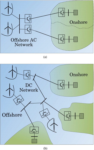
Illustration of offshore AC and DC hub concepts are shown in Figure . Wind power transfer using point-to-point VSC–HVDC transmission system from offshore AC hub offer advantage of not installing DC circuit breaker, and the power can be distributed to different countries. Further, the size of an offshore converter of a single HVDC transmission line is not required to be equal to the net power of the wind power plants. Though, the combined power of all offshore converters should be equal to the net wind power [Citation8]. The network configuration shown in Figure (a) may produce unnecessary losses in the offshore converters and AC cables while transferring power from one country to another. To avoid these losses, a VSC-based MT–HVDC transmission system is suitable for energy trade between countries [Citation9].
Figure 1. Illustration of offshore AC and DC hub configuration. (a) Offshore AC Hub and (b) offshore DC Hub
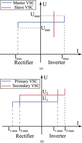
A stable operation of the DC network requires that at least one of the converters must control the DC voltage which is typically done by onshore converters. For the multi-terminal direct current (MTDC) network, there are several voltage control strategies proposed in the literature such as centralized DC slack bus control, voltage margin control, and distributed voltage droop control [Citation10]. Example of master–slave and voltage margin control characteristics are illustrated in Figure . The master–slave control has two main limitations. Firstly, the capacity of the master converter must be equal to the sum of the slave converters. Secondly, a communication system is required in order to make any slave converter to master in case the master converter become malfunction. The reliability of this control principle is very low and highly depends on the communication signal. In order to increase the reliability, more than one converter requires to be set to control the DC voltage with some voltage set-point margin [Citation11,Citation12]. The characteristic curve of the voltage margin control is shown in Figure (b). In this scheme, master converter has main responsibility to control the DC voltage in normal condition and others are working in constant current mode. In case of exceeding master converter power limits, the voltages in the network start rising and reaches voltage threshold limits at the slave converter busbar, hereby enforcing slave converter to regulate DC voltage instead of current. In this control scheme, it is important that the master converter voltage set-point must be less than the slave converter threshold limit. As a disadvantage, the voltage margin control only allow fixed power sharing and it needs several control loops which make the voltage regulation slower [Citation13].
Figure 2. The characteristic curve of master–slave and voltage margin control principle. (a) Master-slave principle and (b) voltage margin principle
A decentralized control system such as droop control increases the controllability and reliability in the system. The principle of the DC voltage droop control is similar to the frequency regulation in the AC system. In the scheme, the change in DC power received by the converter proportionally changes the DC voltage. For a stiff voltage control, the net power in the offshore DC grid can be shared among onshore converters by adjusting the slope of the droop values. Also, the network can be operated even if one or more onshore converters malfunction [Citation14].
The realization of a “SuperGrid” at the North and Baltic Sea may require the benefits of both offshore AC collector system and MTDC network. An offshore AC network allows the centralized collection of offshore energies located at long distances, and the MTDC network can provide the mean of transferring this collected energy at different onshore grids and enable the trade between them [Citation15]. In such a network, energy trade can be performed by converters in the offshore AC grid and onshore converters of MTDC network. In order to establish effective control of power flow in the network, additional criteria is required to calculate the control parameters for both offshore and onshore converters.
In this article, the frequency and AC voltage droop schemes is applied in order to control the power flow in the offshore AC grid. The droop gains selection criteria is proposed to distribute the power among the offshore grid converters. The power distribution in the MTDC system is achieved by selecting the desire proportional gains of DC voltage control of onshore converters. The steady-state criteria for onshore converter DC voltage is also proposed which calculate the control values according to the trade requirement. In the end, the simulation and analysis of hybrid AC/DC grid is performed to check the effectiveness of the propose criteria.
2. Control principle of offshore grid
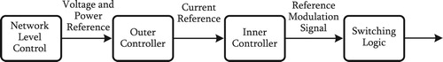
In a stand alone network such as an offshore AC network, the offshore VSCs of HVDC transmission line energize the network and behave like a slack source [Citation16,Citation17]. The voltage and frequency droop schemes are suitable in order to operate the parallel connected VSCs. The advantage of droop scheme is to have multiple slack sources in the network and the communication between VSC–HVDC transmission systems is not required for power sharing during normal operation as well as in the failure of any transmission system [Citation8]. Furthermore, the droop gains also offer an additional degree of freedom to control the reactive power in the offshore AC network. The grid-forming control system of offshore VSC is shown in Figure . The system is based on vector control method which consists of inner current and outer voltage control loops [Citation18]. An overview of cascaded VSC control system is given in Figure . The inner current closed loop provide the fast current dynamic response. The reference signal for the current loop is generated by outer voltage control. The outer voltage control loop maintain the desired voltage level at the controlling busbar. The detail of inner and outer control loop parameters selection procedure are given in [Citation19,Citation20]. The controlling busbar is the filter bus in the converter substation as shown in Figure . The network level control is implemented locally in each VSCs control system which consists of frequency and voltage droop schemes. The frequency and voltage impose by VSC can be defined as (Equation1
(1)
(1) ).
(1)
(1) Here,
is the imposed frequency of
VSC,
and
are the rated frequency and voltage value,
is the frequency droop gain,
is the voltage droop gains,
and
are the actual active and reactive power of the
VSC,
is the imposed voltage of
VSC,
and
are the initial active and reactive power operating point.
Figure 3. The grid-forming control of the offshore converter for parallel operation of VSC–HVDC transmission systems.
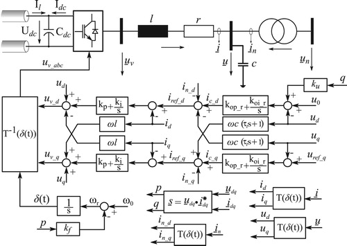
Figure 4. Overview of cascaded voltage source converter control.
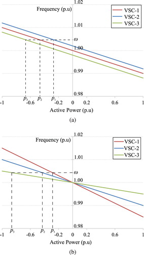
The power sharing can either be done by power set-points or droop gains value. The impact of both techniques on the system is addressed in [Citation21,Citation22]. The comparison of active power sharing technique is illustrated in the Figure . The power sharing control using set-point produce better frequency and power transient response, however, the power will flow from one converter to others when there is no wind power infeed. Power exchange between countries with this scheme produces additional losses in offshore converters and offshore AC cables which is not desirable and can be avoided through other export network topology such as multiterminal HVDC system.
Figure 5. Comparison of active power sharing techniques. (a) Using set-points and (b) using droop gains
Different droop gain value can be assigned to distribute the power among offshore converters. The change in the network frequency and the active power of VSC can be calculated using (Equation2
(2)
(2) ). Where, n is the total number of grid-forming VSCs in the offshore AC grid, and
is the total active power sum of all the active power flowing through each grid-forming VSCs.
(2)
(2) Here, the condition given in (Equation3
(3)
(3) ) is applied.
(3)
(3) Unlike frequency, the VSCs control busbar voltages are not linked with the common bus and each VSCs bus voltage converge to different equilibrium point. Without voltage droop characteristics, VSCs maintain the respective bus voltage level at the predefined value and the power flows through them according to the impedance of the network. It is clear that the VSCs have to balance the reactive power in the offshore AC network which depends on the grid power flow. However, the contribution of reactive power balancing by each VSC can be controlled using voltage droop scheme. Similar to the active power sharing control, the reactive power sharing is controlled using voltage droop gain instead of reactive power set-point as expressed by (Equation4
(4)
(4) ).
(4)
(4)
2.1. Active power sharing in offshore AC grid
The selection of frequency and voltage droop gains for the steady-state operation depends on the operational requirement and the long-term voltage stability. The main operational requirement is the ability to control the power distribution among the VSC–HVDC transmission systems which could be an operator specification.
Let, the active power of VSC is expressed as a factor α of the total power () in the offshore AC grid. The active power of each VSCs can be expressed as (Equation5
(5)
(5) ) for n grid forming VSCs.
(5)
(5)
Also, it is known that the total power must be equal to the sum of the VSCs power, thus (Equation5(5)
(5) ) can be simplified as (Equation6
(6)
(6) ).
(6)
(6) In order to satisfy condition given in (Equation6
(6)
(6) ), the
VSC sharing factor must be defined as (Equation7
(7)
(7) ).
(7)
(7) The condition of the nth VSC active power can be defined as (Equation8
(8)
(8) ) by substituting (Equation7
(7)
(7) ) in (Equation5
(5)
(5) ).
(8)
(8) For n−1 VSCs, the distribution factor must be defined in order to determine the droop values. This can be achieved by defining the relationship between the distribution factor and the droop values by comparing (Equation2
(2)
(2) ) with (Equation5
(5)
(5) ). Thus, the distribution factor of any ith VSC can be written as (Equation9
(9)
(9) ).
(9)
(9)
2.2. Reactive power sharing in offshore AC grid
Consider β as the reactive power distribution factor then the reactive power of each grid forming VSCs in the offshore AC network can be expressed as (Equation10(10)
(10) ).
(10)
(10) Here,
is the sum of the reactive power flowing through each grid-forming VSCs. Also, the reactive power sharing condition given in (Equation11
(11)
(11) ) must be satisfied.
(11)
(11) Unlike frequency droop scheme, the relationship between reactive power sharing factor (β) and the voltage droop gains (
) cannot be explicitly defined because of not having a common link between the VSCs control busbars. However, the computation of voltage droop gains can be done with the common variable i.e reactive power. Thus, the condition for reactive power sharing of
VSCs can be defined as (Equation12
(12)
(12) ) for n grid-forming VSCs in the offshore AC network by substituting (Equation11
(11)
(11) ) into (Equation10
(10)
(10) ).
(12)
(12) Note that n−1 reactive power distribution factor (β) is required to be defined in order to satisfy (Equation11
(11)
(11) ), also one system function would be redundant if it is defined by (Equation12
(12)
(12) ) for all grid-forming VSCs. Furthermore, the busbars voltages are not considered in the selection of droop gains.
The reactive power flow of the VSCs changes the controlling bus voltage level, and the difference between these bus voltages may generate additional reactive power. The required reactive power sharing can be achieved at high gain as well as at lower, however the interaction between VSCs control busbars would be large at high voltage droop gains. The impact of the voltage droop on the network can be understood by analysing the change it causes in the reactive power at the load bus.
Consider that a load bus is directly connected with a VSC control bus. The reactive power flow equation of the load bus can be expanded for the branches that are connected with the VSC control bus (i.e filter bus) as (Equation13(13)
(13) ).
(13)
(13) Substitution of the voltage droop equation given in (Equation4
(4)
(4) ) into (Equation13
(13)
(13) ) yield (Equation14
(14)
(14) ).
(14)
(14)
(15)
(15)
Here, z is the total number of AC busbars in the offshore AC network, l is the load bus connected with the ith VSC, i is the VSC control busbar index,
, and
.
The first three terms in (Equation15(15)
(15) ) are the reactive power mismatch without voltage droop scheme at the load bus. The droop gain add the reactive power (
) at the load bus as the function of VSC reactive power. In case of one grid-forming VSC in the network, this additional reactive power largely impact on the network voltages since there are no sources available other than cable capacitance to absorb it. The voltage droop scheme is not required to be applied for single grid-forming VSC in the offshore AC network. However, the multiple grid-forming VSCs in the offshore AC network can exchange this additional reactive power (
) for balancing and to reduce its impact on the network voltages. To achieve this, the criteria given in (Equation16
(16)
(16) ) can be applied to determine the droop gains.
(16)
(16) Here, y is the total number of busbars that is connected with ith VSCs reference bus, n is the total number of grid-forming VSCs in the offshore AC network,
and
are the voltage droop gain and reactive power of ith VSC.
3. Control principle of MT–HVDC network
In the MTDC system for the offshore wind integration, all the onshore side VSCs can be set to control the DC voltage. Usually, the DC resistance in the network is relatively small even for long cables [Citation23,Citation24]. The DC voltage control using proportional-plus integral (PI) regulator in the MTDC system makes VSCs react as voltage sources connecting in parallel at the common bus with very low equivalent resistance. This could cause large active power flow among them and lead system into instability. Thus, a proportional (P) control can be applied instead of PI regulator for DC voltage control. A proportional controller does not enforce the bus voltage at the given set-point rather the error in the voltage from the set-point enable the balancing of the network through multiple VSCs.
3.1. Onshore VSC control for MTDC network
The onshore substation and its control system is shown in Figure for MTDC network. The feed-forward network current input () should not be included in order to control with only voltage feedback signal to avoid conflict between VSCs in MTDC configuration. The closed loop transfer function can be derived from the stability model of the DC voltage control of a VSC given in Figure (c).
(17)
(17) Here,
is the time constant of the current closed loop,
is the DC capacitance,
is the DC voltage controller,
is the voltage set-point,
is the network current, and
is the output voltage. Note that the closed loop transfer function given in (Equation17
(17)
(17) ) represents a single VSC DC voltage control dynamics. The stability conditions of only one VSC controlling DC voltage in the DC network are
. Using (Equation17
(17)
(17) ), the steady-state DC voltage equation of a VSC can be determined by setting all the derivatives to zero, i.e
.
(18)
(18) It is clear from (Equation18
(18)
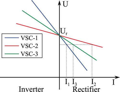
(18) ) that the DC voltage control now exhibit a droop characteristic. The U–I characteristic of the three onshore VSCs DC voltage control is shown in Figure . The proportional gain for the DC voltage control act as a slope (droop gain) of the U–I curve. By selecting the appropriate gains, the current or power distribution among VSCs can be controlled [Citation25]. Note that the illustration of the U–I characteristic is ideal and the resistance of the DC network is neglected. The DC cable resistance also affects the power sharing criteria therefore an optimum power flow (OPF) algorithm is required to determine the steady-state operating point and the desire droop gains [Citation26].
Figure 6. Onshore VSC substation and its control scheme for MTDC network. (a) Onshore VSC Control, (b) DC voltage control with proportional regulator, and (c) stability model of DC voltage with proportional regulator
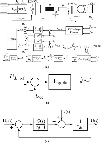
Figure 7. U–I characteristic of onshore VSCs DC voltage control to operate MTDC network.
3.2. DC voltage droop gain selection criteria
The DC voltage droop gains can be selected within the stable operational range based on the DC network power flow solution and the steady-state power sharing criteria. The steady-state solution of the DC network can be found using current flow equation. Using (Equation19(19)
(19) ), the load bus current injection can be defined as:
(19)
(19) Here,
is the current injected at the
DC bus, n is the total number of the DC busbar in the network,
is the voltage of
DC bus,
is the voltage of
DC bus, and
is the conductance between DC bus node i and j.
The VSC controls the DC voltage therefore its busbar can be designated as slack or reference bus possessing the droop characteristics. The DC slack bus voltage equation can be defined by using VSC control equation i.e.
(20)
(20) Here, k is the index of the DC bus connected to the onshore VSC,
is the rated DC voltage,
is the slope of the U–I characteristic of
VSC, and
is the
VSC current.
The total power in the DC network is required to be distributed among all onshore VSCs. Thus, the current of the VSC can be written as the sharing factor of the total current.
(21)
(21) Here,
is the current sharing factor of
VSC, and
is the sum of all the VSC current that has droop characteristic. For any z converters controlling DC voltage,
can be calculated as
(22)
(22) By substituting (Equation22
(22)
(22) ) in (Equation21
(21)
(21) ), the current sharing equation can be defined for any kth DC voltage controlling VSC as given in (Equation23
(23)
(23) ). Furthermore, the sharing factor must satisfy the condition given in (Equation24
(24)
(24) ).
(23)
(23)
(24)
(24)
4. Analysis of hybrid AC/DC grid
The power sharing criteria is a steady-state operational requirement, and an optimal power flow algorithm is required to find the network voltage, current, power, and desire droop gain values. The upper and lower boundaries of the state variables must be defined by considering their stable operational range. The boundary limits of the droop slope can be determined by dynamic and stability analysis of the MTDC system [Citation27]. In order to analyse and illustrate the operation and control of hybrid AC/DC offshore grid, the network shown in Figure is simulated in Simulink environment.
Figure 8. Integration of offshore AC and DC networks.
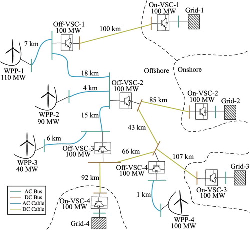
In the network, three wind power plants are connected together with HVAC cables to form offshore AC collector system. The fourth wind power plant is located far from both onshore grids and the collector system; therefore, it is interlinked with the HVDC system. Three onshore grids are connected with the offshore AC collector system via MT–VSC HVDC transmission system, and an onshore grid is interconnected with the AC collector system via VSC–HVDC system in the point-to-point configuration. All the VSCs have the same rated active power i.e 100 MW, and the rated apparent power is 112 MVA. The network voltages and cables parameters are given in Table .
Table 1. Network voltages and cables parameters for combined AC and DC grid.
The offshore VSCs “Off-VSC-1”, “Off-VSC-2”, and “Off-VSC-3” are operating in the grid-forming mode with frequency and voltage droop schemes as explained in Section. 2, and their substation configuration is based on Figure . The net maximum active power in the offshore AC network is 240 MW. The active power sharing is considered as equal among the offshore VSCs, thus all of them have same frequency droop gains i.e p.u. The voltage droop gain for “Off-VSC-1”, “Off-VSC-2”, and “Off-VSC-3” are calculated as
,
p.u and
p.u respectively. The offshore VSC “Off-VSC-4” is also operated in grid-forming mode but without frequency and voltage droop scheme, and it substation configuration is same as shown in Figure with
p.u.
The onshore VSC “On-VSC-1” is controlling the DC voltage solely since it is connected in the point-to-point configuration and its substation configuration is same as shown in Figure but with PI control scheme. The PI control parameter selection procedure are explained in detail in [Citation28]. Furthermore, the onshore VSCs “On-VSC-2”, “On-VSC-3”, and “On-VSC-4” are forming a MTDC network therefore they are controlling the DC voltage with droop characteristics as explained in Section 3. With equal active power sharing criteria among the VSC in offshore AC collector network, the net maximum active power in the MTDC network is 260 MW. It is also considered that the onshore VSCs in MTDC networks are sharing active power equally at the rated power. The proportional gains value of the DC voltage control and DC current flow values are give in Table . Furthermore, each wind power plants is an aggregate model and the type IV wind turbines are considered in the analysis which can control the active and the reactive power independently. Since this article do not focus on the wind turbine dynamics, the further detail on the wind turbines model is not discussed [Citation29].
Table 2. MTDC network operational scenarios and voltage controller gains.
The operation of the offshore grid is analysed by applying step change in the wind power generations. All the wind power plants have 0.98 inductive power factor in order to support the network voltages. For analysis, WPP-1, WPP-2, WPP-3, and WPP-4 wind power generation are changed from zero to maximum at 3.0 s, 6.0 s, 9.0 s, and 12.0 s respectively. The responses of the active and reactive power flow of VSCs in the offshore AC network are shown in Figure . The results are in the per unit of rated apparent power i.e 112 MVA, and generator oriented sign convention is applied. The net active power in the offshore AC network formed by “Off-VSC-1”, “Off-VSC-2”, and “Off-VSC-3” is greater than a single offshore VSCs active power transmission capacity. The frequency droop scheme enable the control over the active power distribution among them. The active power response shows that the power distribution among these VSCs is equal according to the power sharing criteria. After 10.0 s, each offshore VSCs in the AC collector network are receiving 0.7143 p.u active power. The WPP-4 is not connected with the AC collector network thus “Off-VSC-4” is receiving the full wind power generation i.e 0.9 p.u. Although the wind power plants are absorbing the reactive power (inductive) from the network, the VSCs in the offshore AC network requires to flow inductive reactive power as shown in Figure (b). This is due to the offshore AC cable capacitance which is comparatively higher than the onshore AC cables. The reactive power can be managed in the offshore AC network by both offshore wind power plants and VSCs. On the other hand, the “Off-VSC-4” is flowing capacitive reactive power since the AC cable connected with WPP-4 is not long.
Figure 9. The power response of offshore VSCs. (a) Active power response and (b) reactive power response.
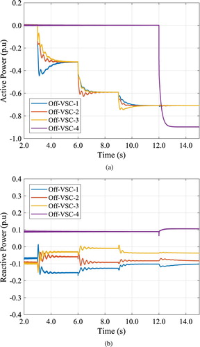
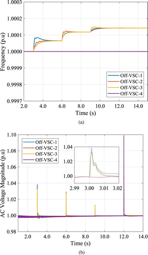
The offshore VSCs formed the AC collector network by imposing the frequencies and controlling the voltages. The response of the offshore VSCs frequencies and voltages are shown in Figure . It can be observed that the offshore AC network frequency is raised above the nominal value at steady-state. This change in the frequency enable the power distribution among the offshore VSCs. On the other hand, the frequency imposed by “Off-VSC-4” is constant since there is no other VSC to share the active power. The energizing of the offshore network is mainly done by controlling the voltage through VSC outer voltage control. Note that there is lack of inertia in the offshore AC network since only static devices (only VSCs) exist in it. Any sudden change in the power imbalance in the network will directly impact the voltages, and VSCs voltage control has to ensure the network stability. The response of the offshore network AC voltages are shown inFigure (b). It is clear that the VSC voltage control is robust and the network voltage reaches the steady-state value fast to ensure network stability i.e voltage response settling time is 20 ms. The maximum voltage rise in the offshore AC network is 1.04 p.u, and the voltage rise due to change in WPP-4 wind power is approximately 1.10 p.u.
Figure 10. The response of offshore VSCs frequencies and their corresponding busbar voltages. (a) Frequencies imposed by offshore VSCs and (b) AC voltages at VSCs busbars.
The response of the active power flowing through the onshore VSCs and the DC voltages at these converters busbars are shown in Figure . The “On-VSC-1” is injecting approximately 0.7143 p.u active power into the “Grid-1”. The active power supply into this grid can only be increased by altering the power sharing factor of “Off-VSC-1”. However, the supply of active power into other onshore grids can be controlled either by the power sharing factor within the MTDC network or with the increase in the MTDC network net power through “Off-VSC-2”, and “Off-VSC-3” converters. Note that the frequency droop scheme in the offshore VSCs do not permit the different active power flow directions with respect to each other. In other words, all the offshore VSCs will supply the active power into the offshore AC network to compensate the network losses when there is no wind power generation. And, they all will receive the active power in case of wind energy generation. This is evidence from the active power response of Figure (a). The total active power losses in the offshore AC network is 2.21 MW which is equally shared by “Off-VSC-1”, “Off-VSC-2”, and “Off-VSC-3” i.e 0.00659 p.u each. Such operational strategy avoid to flow the circulating active power in the loop that can be formed between MTDC and offshore AC network such as around “Off-VSC-2” and “Off-VSC-3”.
Figure 11. The active power and DC voltage response of the onshore converters. (a) Active response and (b) DC voltages at VSCs busbars.
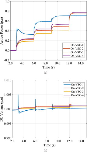
Furthermore, it can be observed from Figure (a) that the active power flow through “On-VSC-2”, “On-VSC-3”, and “On-VSC-4” at the maximum wind power is according to the designed power sharing criteria. Each of them are flowing 0.77 p.u of active power. As it has been explained before that the proportional gain of the DC voltage control of onshore VSCs not only enable the control over the power sharing but also they must ensure the DC network stability. The response of the DC voltages shown in Figure (b) indicates that the voltages are within the operational limits and the DC network is stable.
5. Conclusion
Most of the offshore grid to integrate the wind power plants is based on the radial configuration. Though it simplify the operational control, but it has low redundancy in case of fault, and provides less flexibility to integrate multiple onshore grids. The rapid development of high capacity offshore wind power plant enforce to consider a hybrid AC/DC offshore grid. A hybrid grid may have the mesh configuration as demonstrated in the case study which can flow the active power in the loop and causes the unnecessary losses in the system. The proposed droop selection method ensure that the active power must not flow in loop that is created between the AC and DC grid. Further, the proposed power sharing criteria ensure the steady-state voltage stability and enable power distribution according to operator's requirements. The simulation results demonstrate that an offshore AC network can also be connected with MTDC network with ease.
Disclosure statement
No potential conflict of interest was reported by the author.
ORCID
Muhammad Raza http://orcid.org/0000-0002-4385-5020
References
- Fairley P. Germany jump-starts the supergrid: new developments in high voltage DC electronics could herald an epic shift energy delivery. IEEE Spectr. 2013 May;50(5):36–41. doi: 10.1109/MSPEC.2013.6511107
- Ergun H, Van Hertem D, Belmans R. Transmission system topology optimization for large-scale offshore wind integration. IEEE Trans Sustain Energy. 2012 Oct;3(4):908–917. doi: 10.1109/TSTE.2012.2199341
- Bresesti P, Kling WL, Hendriks RL, et al. HVDC connection of offshore wind farms to the transmission system. IEEE Trans Energy Convers. 2007 Mar;22(1):37–43. doi: 10.1109/TEC.2006.889624
- Palone F, Schembari M, Lauria S, et al. Very long distance connection of gigawatt size offshore wind farms: extra high voltage AC versus high voltage DC cost comparison. IET Renew Power Gener. 2016 May;10(5):713–720. doi: 10.1049/iet-rpg.2015.0348
- Gustavsen B, Mo O. Variable transmission voltage for loss minimization in long offshore wind farm AC export cables. IEEE Trans Power Deliv. 2017 Jun;32(3):1422–1431. doi: 10.1109/TPWRD.2016.2581879
- Deckar JD, Kreutzkamp P. “Offshore electricity grid infrastructure in Europe: a techno-economic assessment,” OffshoreGrid (3E Coordinator), Brussels, Tech. Rep., oct 2011.
- De Decker J, Tambke J, Voelker J, Michalowska-Knap K. An offshore transmission grid for wind power integration: the European techno-economic study offshore grid. In: IEEE PES general meeting. IEEE; 2010 Jul. p. 1–8.
- Raza M, Penalba MA, Gomis-Bellmunt O. Short circuit analysis of an offshore AC network having multiple grid forming VSC-HVDC links. Int J Electr Power Energy Syst. 2018 Nov;102:364–380. doi: 10.1016/j.ijepes.2018.05.009
- Teixeira Pinto R, Alejandro C, Aragues Penalba M, A fast methodology for solving power flows in hybrid ac/dc networks: the European North Sea supergrid case study,” In: PCIM Europe 2016; International Exhibition and Conference for Power Electronics, Intelligent Motion, Renewable Energy and Energy Management; 2016 May 10–12, Nuremberg: IEEE; 2016. p. 2211–2218.
- Longatt FG. Optimal steady state operation of a MTDC system based on DC independent system operator objectives. In: 11th IET International Conference on AC and DC Power Transmission. Loughborough (UK): IET. Institution of Engineering and Technology. 2015 Jul. p. 1–7.
- Wang Z-d, Li K-J, Ren J-g, et al. A coordination control strategy of voltage source converter based MTDC for offshore wind farms. IEEE Trans Ind Appl. 2015 Jul;51(4):2743–2752. doi: 10.1109/TIA.2015.2407325
- Li H, Liu C, Li G, et al. An enhanced DC voltage droop control for the VSC HVDC grid. IEEE Trans Power Syst. 2017 Mar;32(2):1520–1527. doi: 10.1109/TPWRS.2016.2576901
- Rault P, Colas F, Guillaud X, et al. Method for small signal stability analysis of VSC-MTDC grids. In: 2012 IEEE Power and Energy Society General Meeting. San Diego (CA): IEEE; 2012 Jul. p. 1–7.
- Gavriluta C, Candela I, Luna A, et al. Hierarchical control of HV MTDC systems with droop based primary and OPF based secondary. IEEE Trans Smart Grid. 2015 May;6(3):1502–1510. doi: 10.1109/TSG.2014.2365854
- Brouwers J. TenneT news: tennet presents hub and spoke concept for large scale wind energy on the North Sea. Online, TenneT GmbH, Jun 2016 [cited 2017 June 23]. Available from: https://www.tennet.eu/news/detail/tennet-presents-hub-and-spoke-concept-for-large-scale-wind-energy-on-the-north-sea/.
- Coelho EAA, Cortizo PC, Garcia PFD. Small-signal stability for parallel-connected inverters in stand-alone AC supply systems. IEEE Trans Ind Appl. 2002;38(2):533–542. doi: 10.1109/28.993176
- Sao CK, Lehn PW. Autonomous load sharing of voltage source converters. IEEE Trans Power Delivery. 2005 Apr;20(2):1009–1016. doi: 10.1109/TPWRD.2004.838638
- Yazdanian M, Sani AM. Internal model based current control of the RL filter based voltage sourced converter. IEEE Trans Energy Convers. 2014 Dec;29(4):873–881. doi: 10.1109/TEC.2014.2353035
- Zhang L, Harnefors L, Nee HP. Modeling and control of VSC HVDC links connected to island systems. IEEE Trans Power Syst. 2011 May;26(2):783–793. doi: 10.1109/TPWRS.2010.2070085
- Raza M, Gomis-Bellmunt O. Control design strategy to enhance fault right through capability of vsc hvdc transmission system interconnecting offshore wind power plant. In: European Wind Energy Association Annual Conference EWEA 2015. EWEA. Paris: EWEA, 2015, pp. 1–9. Available from: http://www.ewea.org/annual2015/conference/programme/info2.php?id2=1125.
- Raza M, Gomis-Bellmunt O. Multi infeed control of VSC HVDC transmission system for offshore wind power plant integration. In: Betancourt U and Ackermann T, editors. 13th International Workshop on Large-Scale Integration of Wind Power into Power Systems as well as on Transmission Networks for Offshore Wind Plants. Berlin: Energynautics GmbH, 2014 Nov. p. 376–381. Available from: www.windintegrationworkshop.org.
- Raza M, Schönleber K, Gomis-Bellmunt O. Droop control design of Multi-VSC systems for offshore networks to integrate wind energy. Energies. 2016 Oct;9(10):826. doi: 10.3390/en9100826
- Akkari S, Petit M, Dai J, et al. Interaction between the voltage-droop and the frequency-droop control for multi-terminal HVDC systems. IET Gener, Transm Distribution. 2016 Apr;10(6):1345–1352. doi: 10.1049/iet-gtd.2015.0814
- Prieto-Araujo E, Egea-Alvarez A, Fekriasl S, et al. DC voltage droop control design for multiterminal HVDC systems considering AC and DC grid dynamics. IEEE Trans Power Delivery. 2016 Apr;31(2):575–585. doi: 10.1109/TPWRD.2015.2451531
- Thams F, Eriksson R, Molinas M. Interaction of droop control structures and its inherent effect on the power transfer limits in multiterminal VSC-HVDC. IEEE Trans Power Delivery. 2017 Feb;32(1):182–192. doi: 10.1109/TPWRD.2016.2600028
- Raza M, Collados C, Gomis-Bellmunt O. Reactive power management in an offshore AC network having multiple voltage source converters. Appl Energy. 2017 Nov;206:793–803. doi: 10.1016/j.apenergy.2017.08.182
- Teixeira Pinto R. Multi terminal DC networks: system integration, dynamics and control [Ph.D. dissertation]. Delft, Netherlands: Technische Universiteit Delft; 2014.
- Raza M, Gomis-Bellmunt O. Dynamic modelling and implementation of VSC-HVDC system the grid connected large offshore wind power plant application. In: SMARTGREENS 2014 - Proceedings of the 3rd International Conference on Smart Grids and Green IT Systems. Barcelona, Spain: INSTICC, 2014. p. 53–62.
- Conroy J, Watson R. Aggregate modelling of wind farms containing full-converter wind turbine generators with permanent magnet synchronous machines: transient stability studies. IET Renew Power Gener. 2009;3(1):39–52. doi: 10.1049/iet-rpg:20070091