
 ?Mathematical formulae have been encoded as MathML and are displayed in this HTML version using MathJax in order to improve their display. Uncheck the box to turn MathJax off. This feature requires Javascript. Click on a formula to zoom.
Abstract
Capacitor Allocation (CA) and Network Reconfiguration (NR) are the traditional methods extensively applied by the researchers for power loss reduction and node voltage improvement in radial Distribution Network (DN) for the past four decades. In recent years, simultaneous optimization of CA and NR is considered to maximize the power loss reduction in a proficient manner in comparison to individual optimization of CA and NR. To solve the objective functions, this work proposes an application of Autonomous Group Particle Swarm Optimization (AGPSO) by optimal allocation and sizing of capacitors with and without NR, under four different cases, subject to satisfying operating constraints. In addition, to ascertain the impact of real power injection on further power loss reduction, this work considers placement and sizing of Distributed Generation (DG) units from single to three optimal nodes in capacitive compensated optimal DN. This proposed methodology is demonstrated using standard IEEE 33 and 69 bus test system and the results obtained by each test case have been compared with other optimization techniques. A significant amount of power loss gets minimized after optimal DG allocation in reactive power compensated optimal DN.
1. Introduction
Most of the DNs are constructed as radial circuits which have only one main source of power supply and the power supply will reach the consumers through feeders (laterals and sub-laterals). As a result, the power losses of the DN get increased with reduction in bus voltage [Citation1]. In India, the average power loss is approximately 30% of the total power generated including power theft [Citation2] considering both transmission and distribution (T&D). Nevertheless, in some states it is still more. Consequently, in order to be more competitive, utilities in the distribution sectors are presently given more attention in minimizing the power losses as it reflects the cost of electricity.
A proficient operation of DN can be done by using NR. NR has been recognized with great importance from 1988 onwards. Hence, many researchers are focussing their researches on optimal NR-based optimization problems [Citation3–6]. By using NR, the advantages, such as reduction in power loss, improvement in bus voltage, load congestion management and reliability of the DN, get improved and this is reflected in the performance improvement of the DN. Although the DN is set as a weak mesh network, its operation is radial only for effective coordination with protection schemes and to reduce the fault level.
Since the 1960s, the application of shunt capacitors has been one of the imperative research studies in radial DN. A part of reduction in power loss could, however, be done by optimal allocation of capacitors which feed a part of reactive power demand. It is well known that by the addition of capacitors in radial DN the benefits, such as reduction in power loss, increase in feeder capacity release as well as power quality improvement, bus voltage enhancement, reduction in kVA demand, improvement in power factor at the sub-station bus etc., can be obtained. Since capacitors lower the reactive requirement from the main source, more real-power output is available. In recent times, many researchers have focused their research on capacitor placement problems [Citation7–17] in DN.
The previous research studies, dealt with either NR or CArelated problems, resulted in unnecessary losses and could not yield minimum loss configuration [Citation18]. Optimal capacitor allocation (CA) along the DN with NR is a non-linear, complex, combinatorial and mixed integer optimization problem which includes integer and binary variables that correspond to the optimal locations at which capacitors are required to be placed and the number of capacitor banks installed at each bus. It is also a computationally in-depth problem whose dimension increases extremely with network size. Only a few research papers are available in the literature for optimization of CA and sizing together with NR [Citation19–30].
Minimization of power loss and node voltage deviation as objective, optimal CA with NR under different cases, considering HSA as an optimization method has been proposed in [Citation19]. Combined optimization of CA and NR under five different cases to reduce power loss has been investigated in [Citation20,Citation21]. IBPSO has been utilized to solve the simultaneous NR and optimal CA problem. This method employs a different logically operated structure such as AND, OR, and XOR for the optimization algorithm. NR and CA problem under three different cases using OBDE as an optimization tool has been suggested in [Citation22]. In this work, the cost of the capacitor and energy loss has been taken as an objective. LSF is used to identify the potential location for capacitor installation and the reactive power injection value is fine-tuned by OBDE. NR and CA problem, using a Hybrid Shuffled Frog Leaping Algorithm (HSFLA) associated with fuzzy objective function, has been suggested in [Citation23]. Separate optimization of total real power loss, node voltage deviation and feeder balancing are the goals of this work. Similar to [Citation23], another work, considering HBB-BC as an optimizing method, has been presented in [Citation24]. Ordinal optimization (OO)-based optimal location and sizing of capacitors with NR under three different cases considering power loss reduction as the objective has been reported in [Citation25]. Cost of total energy loss, capacitor purchase cost and voltage constraint penalty as the objective, optimal allocation and sizing of capacitors with and without NR under three cases considering three different load levels (75%, 100% and 125%) were dealt in [Citation26]. Modified Flower Pollination Algorithm (MPFA) has been used in this paper to solve the objective function. NR and CA problem, based on a combination of salp swarm algorithm and real-coded genetic algorithm (SSA-GA) under three scenarios, to reduce power loss has been discussed in [Citation27]. Real power loss reduction, Voltage profile improvement and annual cost saving increase as the objective, optimal allocation and sizing considering two techniques of operations, such as individual OCP and dual OCP-DSR, have been proposed in [Citation28]. In this paper four different optimization algorithms are engaged (MBBO/CS/MIC/MBFBO) to solve multi-objective functions. Self-Adaptive Harmony Search Algorithm (SAHSA) as an optimization method feeder reconfiguration simultaneously with capacitor placement under five different scenarios, considering 100% and 120% loading conditions, to minimize the active power loss and to minimize the bus voltage deviation, has been reported in [Citation29]. DSR (NR)/dual DSR-OCP (NR-CA)-based optimization for IEEE 33 and 69 bus test system were presented in [Citation30]. To find the optimal solution for significant loss reduction and bus voltage profile enhancement, Modified Biogeography Based Optimization (MBBO), Binary Teaching Learning Based Optimization (BTLBO) and Discrete Dolphin Echolocation (DDE) algorithm have been adopted.
Distributed generation (DG) plays a significant role in the modern DN which is associated directly with the DN or on the end-user location. Due to the terrific growth in power demand, the utility DG power has to satisfy the increased power demand. To improve the network performance, such as reduction in power loss and the bus voltage profile enhancement, DGs must be placed optimally with appropriate size while maintaining the system stability which is a complex combinatorial and non-linear optimization problem. Many researchers have solved the DG allocation and sizing problem using various optimization methods. Recently, to reduce power loss in the radial DN, optimal allocation of all the three techniques, such as NR, DG and CA, has been adopted [Citation31–35].
The main focus of this work is to achieve reduction in I2R loss by reactive power compensation at three and four optimal locations considering with and without NR (cases A to D). This is the initial step of power loss minimization. Furthermore, this work considers real power injection at single to three optimal locations after optimal allocation and sizing of capacitors in the reconfigured DN (cases E and F). This is to identify the impact of DGs on the reduction of additional power loss after reactive power compensation with NR subject to satisfying all the equality and inequality constraints; it has been projected as the next stage of power loss reduction. The node voltage profile has been enhancing further and considerable reduction in additional power loss is also achieved. The method has been tested and verified using standard IEEE 33 and 69 bus test systems. In the light of the above-discussed features, the contributions of this work includes (i) Study of the impact of power loss using DGs (three optimal nodes) in capacitive compensated reconfigured DN (capacitors at three and four optimal locations) (ii) Capacitor sizing simultaneous with NR at three/four optimal nodes.
The entire work has been set in five sections. Section 2 discusses the objective function with Distribution Network Power Flow (DNPF). Section 3 deals with the introduction of AGPSO and its capability to solve the proposed problem. Discussions on the simulation and the results achieved with the comparison have been done in Section 4 and finally Section 5 concludes the work carried out in this work followed by the references.
2. Objective function and power flow
The objective function is to get maximum reduction in power loss/additional power loss by optimal placement and capacity determination of capacitors (at three and four nodes) with NR. Allocation of DG units at three optimal locations in the reactive power compensated optimal DN while satisfying system equality and inequality constraints.
2.1. Distribution system power flow (DNPF)
Power flow (PF) study plays a very important task for appropriate planning of power transfer to meet the load demands in the modern power system network which is a major task too. From the previous literature, it has been understood that the traditional PF methods, such as Gauss–Seidal, Newton–Raphson and Fast Decoupled PF, used for the Transmission network cannot be used for radial DN because of the radial nature of the DN with high R/X ratio and difficulty in handling power balance equations. In this paper, a robust, fast, flexible and efficient method of PF suitable for radial DN is used which is based on recursive function and a linked-list data structure designed PF study [Citation36]. It has an advantage of the radial nature of DN and also the ability to update easily and to accommodate the reconfiguration of DN and embedded generation. The author exploits a tree-like structure of RDN with efficient use of dynamic data structure.
Let us take a two-bus system (m, m + 1), the branch (p) connecting the two buses has an impedance value (z = r + jx). The real and reactive power demand at bus “m” is Pm + jQm and the real and reactive PF beyond “m + 1” is Peff(m + 1) + j Qeff(m + 1). Let the load at the receiving end be (P(m + 1) + j Q(m + 1)) and PLOSS is the active power loss at branch “p”. The bus voltage and phase angle will be obtained by using the DNPF method by applying the above parameters at the load bus according to Equations (1) and (2) [Citation36]. Using the known parameters, such as receiving end real and reactive power, sending end bus voltage with angle (δ) and the line impedance, the receiving end bus voltage with angle for the above-said network can be calculated.
(1)
(1)
(2)
(2) At the end of each iteration, DNPF will check the difference between the sum of powers flowing out of the line connected to each bus and the net power injected into each bus. Equations (3) and (4) show the convergence criteria
(3)
(3)
(4)
(4) The real and reactive power loss in a distribution feeder section “p” is given by
(5)
(5)
(6)
(6) Total real and reactive power loss power loss, incurred in the whole network including all feeders, may be calculated by summing up all the branches of the RDN as given below:
(7)
(7)
(8)
(8) where TNB indicates the total number of branches. Y(m,m + 1) is the element (m, m + 1) in bus admittance matrix, θ(m,m + 1) is the angle of Y(m,m + 1) and δ(m) and δ(m + 1) are the voltage angles of bus “m” and “m + 1”, respectively.
2.2. Problem formulation
(9)
(9) Subject to Equality Constraints
(10)
(10)
(11)
(11) Subject to Inequality Constraints
(12)
(12)
(13)
(13)
(14)
(14)
(15)
(15)
(16)
(16) where
(for cases A to D);
(for cases E and F);
Radial configuration constraint: It is mandatory that the DN should be maintained in radial to avoid excess current flow. Therefore, several constraints must be considered to retain the radiality structure during NR. For the selection of switches, many rules and procedures have to be implemented. Sectionalizing switches that do not belong to any loop and connected to the sources that contributed to a meshed network have to be closed.
Isolation constraints: By doing NR, all the nodes must be energized and also reactivated to ensure that all loads get power supplies, that is, during reconfiguration process, all buses should stay connected and no customer should be left unconnected.
3. Proposed technique (AGPSO) [38]
PSO is an evolutionary computation technique that has been proposed by Kennedy and Eberhart [Citation37]. It is inspired from the social behaviour of bird flocking which uses a number of particles flying around the search space to find the best solution. The particles trace the best location (best solution) in their paths over the course of iterations. These concepts have been mathematically modelled using a position vector (x) and velocity vector (v) of length of problem (number of variables). In the course of iterations, a particle adjusts its position and velocity as follows:
(17)
(17)
(18)
(18)
In this paper, PSO is modified by a mathematical model of different functions with diverse slopes, curvatures, and interception points being employed to tune the socio and cognitive constants of C1 and C2 parameters to generate particles of different behaviours to achieve the desired solution. This modification has led the standard PSO into a modified particle swarm optimization algorithm named AGPSO.
AGPSO is mainly applied to alleviate the two major problems of trapping in local minima and slow convergence rate of PSO in finding the optimal position of switches and placement and sizing of Capacitor banks and DGs. Detailed descriptions about AGPSO are available in [Citation38] with the merits of AGPSO compared with variants of PSO. Updating strategies to tune the C1 and C2 parameters have been given in [Citation38].
3.1. Arrangement of parameters to solve CA with NR and DGs
The use of AGPSO in allocation and sizing of capacitors with NR and allocation of DGs in the reconfigured capacitor allocated radial DN to achieve additional reduction in real power loss which has been described in this segment. The steps to be followed are given below:
Step 1: Initialize the particles Xi of PSO randomly within the boundary limits according to Table . For NR, the total number of Solution Vectors (SV) is 10 (5 tie-switches) (case A). Since this paper considers optimal allocation and sizing of capacitors at three/four nodes, the SVs are equal to six/eight (case C). Optimal nodes for CA and its corresponding sizing are represented as Ncap and Kcap, respectively. Thus the SVs are sixteen/eighteen for cases D and E. Considering cases F and G, the variables are six (two variables for each DG). The optimal node and optimal sizing are represented as NDG and KDG, respectively.
(19)
(19)
Table 1. Typical value of particles (cases B to G).
Thus the total SVs are twenty four considering NR, capacitors at four optimal nodes and DG at three nodes, as given in (19). “T” indicates the population size from a set of random distributions. Only the particles that satisfy all the constraints will be considered as the initial population. Table indicates the minimum and maximum values of capacitors (kVAr) for four optimal nodes and DGs for three optimal nodes. Figure shows the flow chart for the proposed method.
Figure 1. Flow chart of the proposed method (AGPSO).
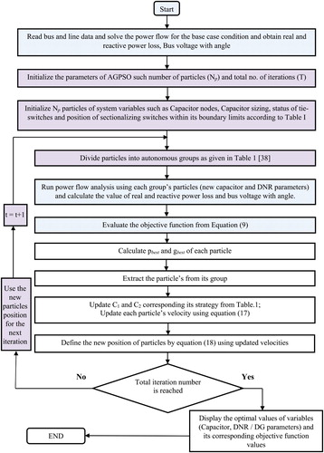
Step 2: Particles Xi are randomly split into some predefined autonomous groups with beneficiary functions according to Table [Citation38].
Step 3: gbest, pbest, and the fitness given in (1) of each particle (XiT) at each iteration have been calculated.
Step 4: For each particle, the coefficients C1 and C2 have been updated using its group’s strategy.
Step 5: Velocities and positions of particles have been updated using (17) and (18).
Change in variable parameters can be obtained by substituting (19) into (17) and (18) when particles change from existing position to a new position. Recently generated variables were obtained at the end of each iteration, former inferior vectors will get replaced and this process cycle gets completed once the maximum number of iterations has reached. For both test systems, the parameters, such as agent size and the number of iterations, are selected as 800 and 100, respectively. Out of three objective function values (AGPSO1, AGPSO2 and AGPSO3), only the best one (the least objective value) will be considered.
4. Case study details simulation results
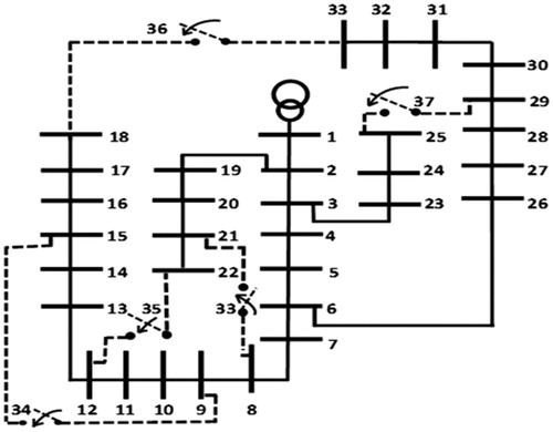
The test system has 33 buses, 32 sectionalizing switches and 5 tie-switches (5 looping branches) as shown in Figure . The system voltage is 12.66 KV. The base MVA and base KV for the test case are taken as 100 and 12.66, respectively. The total apparent power demand of this network is (3715 + j2300) kVA. The total apparent power loss under BC is (211 + j143.135) kVA and the minimum voltage recorded is 0.9038 p.u at bus no. 18. Node No.1 (main source node) is considered as a slack node and all the remaining nodes are considered as load nodes. AGPSO coding has been developed in MATLAB software and runs on an Intel i5 third generation processor with 4 GB RAM. The minimum and maximum voltages have been set as 0.95 and 1.05 p.u., respectively. Only the least value that corresponds to each test case is considered as the best value which are tabulated in the corresponding tables.
Figure 2. IEEE 33 bus test system – BC.
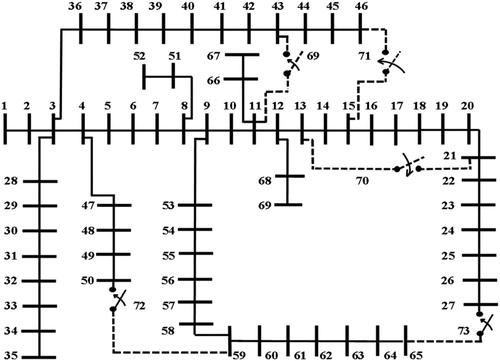
The next test system is IEEE 69 bus test system which has 69 buses, 68 sectionalizing switches, as shown in Figure . Remaining parameter details are similar to those of IEEE 33 bus test system. The total real and reactive power demand of this DN are 3802 kW and 2695 kVAr, respectively. The minimum bus voltage BC is 0.90919 p.u at bus no. 65. The total apparent power loss under BC is (225 + j102.1155) kVA.
Figure 3. IEEE 69 bus test system – BC.
Six different cases have been considered for studying the usefulness of the proposed technique in achieving initial power loss reduction (cases A to D) and minimization of additional power losses (cases E and F). The maximum real and the reactive power injection are assumed to be less than or equal to the total real and reactive power demand of the system including BC real and reactive power losses.
Case A: NR is employed in the BC network with the objective to reduce the power loss.
Case B: To evaluate the power loss, capacitors at three and four optimal nodes have been performed in BC DN.
Case C: This condition is similar to the case B, but NR has been carried out to investigate the usefulness of NR in power loss reduction.
Case D: Keeping the optimal location obtained under case B, NR has been performed simultaneously with capacitor sizing to examine the effectiveness of power loss minimization compared to case C.
Case E: To assess the additional power loss minimization, allocation and sizing of DG units from a single optimal node to three optimal nodes have been installed after case C.
Case F: To check the effectiveness of the additional power loss minimization, DGs are placed optimally from a single node to three nodes after case D.
4.1. IEEE 33 bus system results and discussions
After optimal NR (case A), the real and reactive power losses have been reduced by 40.4% and 22%, respectively consequent to the opening of five sectionalizing switches 7, 14, 10, 32 and 28 (maintaining radial arrangement) which is better when compared to [Citation3–6,Citation26]. The bus voltage improvement after case A is around 0.04 p.u compared to BC.
In this work, optimal allocation and sizing of capacitors have been considered to distinguish the effect of power loss reduction and bus voltage enhancement under three and four optimal nodes. From Table , it has been seen that a power loss reduction of 34.4% and 35.144% after allocation and sizing of capacitors at three and four optimal nodes. The value of reactive power support is 86.273% of the total reactive power demand plus losses. However, the power loss reduction difference between scenario 1 and 2 under case B is negligible. The bus voltage enhanced after case C is 0.0271 p.u (scenario 1) and 0.0304 p.u (scenario 2) compared to BC. Considering Tables and , by comparing the results obtained under scenario 1 and 2, it is obvious that the proposed method yields the power loss reduction in a better way than other existing methods. But still average bus voltage improvement difference after case B with the other methods is around 0.01 p.u.
Table 2. Results obtained by AGPSO – cases B to D – scenarios 1 and 2 – IEEE 33 bus.
Table 3. Comparison of case B – scenario 1 – IEEE 33 bus.
Table 4. Comparison of case B – scenario 2 – IEEE 33 bus.
Keeping the optimal values obtained under case B, the remaining two cases (cases C and D) have been derived considering NR. NR has been performed after case B to know the effect of power loss reduction under case C. Out of the five tie-switches, four switches (33, 34, 35, 36) have been closed against opening of respective sectionalizing switches in that particular loop to maintain the radiality structure. Using NR the reduction of total real power loss achieved is >60% and also the additional power loss achieved beyond case B is 25.703% (scenario 1) and the reduction in the power loss difference between scenario 1 and 2 is below 1 kW only.
Yet, the power loss reduction difference between cases B and C under scenario 1 is more than scenario 2. Approximately 0.03 p.u of bus voltage improvement is observed after case C compared to case B. It is to be noted that the values of the bus voltage enhanced from BC to case B and case B to case C are almost the same. The progress in bus voltage comparing BC and D (scenarios 1 and 2) is around 0.0588 and 0.0634 p.u., respectively. The performance of the AGPSO in achieving power loss reduction considering cases C and D is depicted in Table and also the results obtained are compared with the other existing methods which are depicted from Tables .
Table 5. Comparison of case C – scenario 1 – IEEE 33 bus.
Table 6. Comparison of case C – scenario 2 – IEEE 33 bus.
Table 7. Comparison of case D – scenario 1 – IEEE 33 bus.
Table 8. Comparison of case D – scenario 2 – IEEE 33 bus.
By comparing the results obtained under cases C and D (scenario 1) with Tables and , it is clear that the proposed method minimizes the power loss in a better manner than [Citation28,Citation19,Citation20,Citation22,Citation26] and also the minimum and the maximum power loss reduction differences are 1.286242% and 8.277% for case C and for case D, 6.439% and 19.5933%, respectively. Better improvement in bus voltage has been noticed compared to other existing methods. Similarly, by comparing the results obtained under cases C and D (scenario 2) with Tables and , it is visible that AGPSO enhances the power loss reduction in a better way than [Citation21,Citation24,Citation25,Citation27,Citation23] and also the minimum and the maximum power loss reduction differences are 6.31663% and 9.40663%, respectively for case C and for case D, a maximum difference of 7.621% has been noticed. However, the minimum power loss difference is negligible. Better improvement in bus voltages is observed compared to other existing methods.
From the above discussion, it is apparent that the performance of AGPSO in power loss minimization is better than other existing methods. Conversely, to prove the performance AGPSO in achieving power loss reduction further, this work considers allocation and sizing of DG units (considering PV renewable power generation) starts from a single to three optimal nodes in capacitive compensated reconfigured DN. Table shows the performance of the real power injection in minimizing the power loss reduction after reactive power injection at three and four optimal nodes (scenarios 1 and 2) in optimal network.
Table 9. Results obtained by AGPSO – cases E and F – scenarios 1 and 2 – IEEE 33 bus.
By optimal allocation of DG units at a single to three optimal nodes, the total real power loss reduction achieved by AGPSO is more than 75%, 90% and 95%, respectively and also the reactive power loss reduction achieved is around 64%, 78% and 91%, respectively. A further power loss reduction of around 15%, 30% and 35% beyond cases C and D has been achieved by the real power injection of around 40%, 65% and 88% of the total real power demand of the network. The bus voltage improvement before and after DG incorporation is from 0.035 to 0.04 p.u. (single node) and from 0.018 to 0.02 p.u (two nodes), respectively. On the other hand, the bus voltage improvement after the allocation and sizing of DGs at three locations is 0.02 and 0.0983 p.u, respectively considering scenarios 1 and 2.
By comparing Table , it is clear that the minimum and the maximum power loss reduction differences between AGPSO with other methods are . 1.53% to 4%. It is obvious that the proposed method minimizes the power loss in an efficient manner. Figures show the bus voltage profile for the cases BC to F considering both scenarios.
Figure 4. Bus voltage profile – cases BC to D – scenario 1.
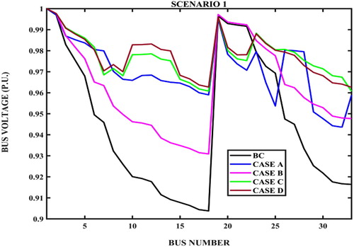
Figure 5. Bus voltage profile – cases BC to D – scenario 2.
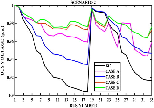
Figure 6. Bus voltage profile – cases C and E – scenario 1.
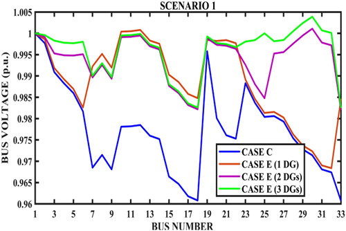
Figure 7. Bus voltage profile – cases C and E – scenario 2.
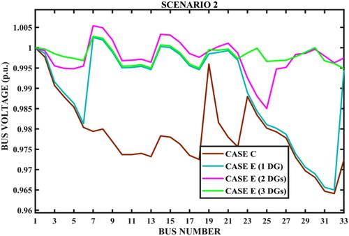
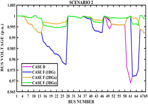
Figure 8. Bus voltage profile – cases D and F – scenario 1.
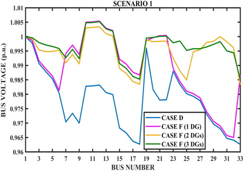
Figure 9. Bus voltage profile – cases D and F – scenario 2.
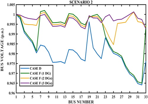
Table 10. Comparison of case G – scenario 1 – IEEE 33 bus.
4.2. IEEE 69 bus system results and discussions
Similar to IEEE 33 bus test system, this test system also underwent six different cases and two scenarios. By successful opening of three sectionalizing switches (71, 72 and 73) against opening three tie switches (14, 58 and 61), a real and reactive power loss reduction of 56.1903% and 9.88%, respectively has been obtained while maintaining radial arrangement. The bus voltage improvement after case A is around 0.04031 p.u compared to BC. It is obvious that the performance of the proposed method is effective in achieving better power loss minimization compared with FPEO [Citation3], BPSO [Citation4], CGA and ICSA [Citation5] and PSO with H-matrix [Citation6].
Table reveals the results obtained using the proposed method. Considering case B, optimal allocation and sizing of capacitors at three/four optimal nodes yields a power loss reduction of 35.5% and 35.83%, respectively by injecting 66.7% and 89.05% of reactive power (scenarios 1 and 2). From case B, it is to be noted that addition of capacitors at fourth node has not yielded the expected effect on power loss reduction, that is, the outcome of scenario 2 on power loss reduction and bus voltage enhancement is very less compared to that of scenario 1. An enhancement in bus voltage after case B is about 0.02161 p.u compared to BC. By comparing the results obtained under scenarios 1 and 2 under case B with the existing methods (Tables and ), it is obvious that the proposed method yields the power loss reduction in a better manner than [Citation8,Citation9,Citation11,Citation12,Citation15,Citation16,Citation39]. But the average bus voltage improvement difference after case B compared with other methods is almost negligible.
Table 11. Results obtained by AGPSO – cases B to D – scenarios 1 and 2 – IEEE 69 bus.
Table 12. Comparison of case B – scenario 1 – IEEE 69 bus.
Table 13. Comparison of case B – scenario 2 – IEEE 69 bus.
From Table , it is visible that a total power loss reduction of around 70% has been achieved under cases C and D (scenarios 1 and 2) which is roughly 35% additional power loss reduction beyond case B and approximately 14% excess power loss reduction compared to case A. Similar to case A, the opening and closing of sectionalizing and tie switches are three only. Bus voltage enhancement after cases C and D is approximately 0.04 p.u. compared to case C. However, the difference in bus voltage improvement between scenarios 1 and 2 (cases C and D) is minuscule.
By comparing AGPSO with other existing methods in achieving power loss reduction considering cases C and D (scenario1), it is to be noted that the results obtained under case C (scenario 1) minimize the power loss in a better manner than CS [Citation28], MIC [Citation28] and MBFBO [Citation28] and also the minimum and the maximum power loss reduction difference is 5.4511% and 15.4166%, respectively. Conversely, the power loss reduction achieved by MBBO [Citation28] is 5.88% more than the value achieved by AGPSO. All the five tie switches have been closed against opening of sectionalizing switches except MIC [Citation28]. By comparing the results obtained under case D (scenario 1), it is perceptible that AGPSO minimizes the power loss better than SASHOA[Citation29], BTLBO [Citation30], DDE [Citation30] and also the minimum and the maximum power loss reduction difference is 2.56% and 22.0887%, respectively. Alternatively, the power loss reduction achieved using MBBO [Citation30] is 3.72% in excess of AGPSO. All the five tie switches have been closed against opening of sectionalizing switches in a particular loop except [Citation29].
Similar to IEEE 33 bus system, real power injection at a single to three optimal nodes after cases C and D has been performed in 69 bus test system to prove the performance of AGPSO in achieving further power loss reduction. Table indicates the effect of the real power injection in minimizing the power loss reduction after cases C and D.
Table 14. Results obtained by AGPSO – cases E and F – scenarios 1 and 2 – IEEE 69 bus.
An additional power loss reduction of around 21%, 26% and 27%, respectively has been gained by injecting 38 to 41.4%, 50 to54% and 62 to65% of the total real power demand of the network. Thus the total power loss reduction increases to around 91%, 96% and 97.5% after real power injection at a single, two and three optimal nodes, respectively. Note that though considerable value of power loss reduction has been obtained by injecting real power up to three optimal nodes, it is economically preferable to select only DG at a single node after cases C and D because selecting the second and third node for real power injection will not yield sufficient power loss reduction compared to real power injection. Table reveals the comparison of case E (scenario 1) with the existing methods. It is visible that the proposed method minimizes the power loss better than [Citation32, Citation34, Citation35]. The maximum power loss reduction difference between [35 (Fuzzy-GA)] with AGPSO is 10.7577% and the power loss reduction difference between [Citation32] with AGPSO is minuscule.
Table 15. Comparison of case F – scenario 1 – IEEE 69 bus.
Figures and show the bus voltage profile from BC to D (scenarios 1 and 2) and Figures show the bus voltage profile for the cases C to F considering both scenarios.
Figure 10. Bus voltage profile – cases BC to D – scenario 1.
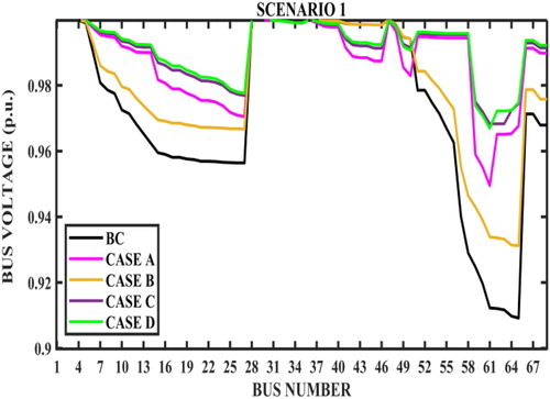
Figure 11. Bus voltage profile – cases BC to D – scenario 2.
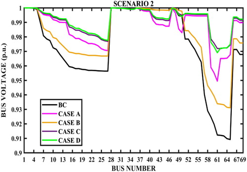
Figure 12. Bus voltage profile – cases C and E – scenario 1.
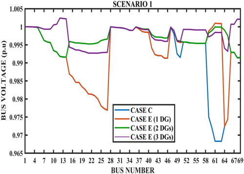
Figure 13. Bus voltage profile – cases C and E – scenario 2.
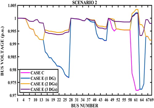
Figure 14. Bus voltage profile – cases D and F – scenario 1.
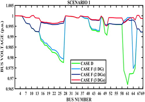
Figure 15. Bus voltage profile – cases D and F – scenario 2.
5. Conclusions
In this work, an evolutionary computation (AGPSO) has been suggested to solve the power loss minimization problem using a combination of CA (at three/four optimal nodes) with and without NR under four different configurations and also allocation and sizing of DGs at single, two and three optimal nodes in reconfigured capacitive compensated radial DN. IEEE 33 and 69 bus test systems are used to evaluate the power loss reduction as well as additional power loss reduction (using DGs). Based on the above study, the following are the important observations:
In this work no sensitivity factor has been adopted to find the optimal location for capacitor/DG placement. AGPSO has to search for optimal location and sizing of Capacitor and DGs
The power loss reduction of DN can be effectively and efficiently minimized by proper NR with allocation and sizing of capacitors at three/four optimal nodes compared with other existing methods.
Allocation and the sizing of DGs from single optimal node to three optimal nodes beyond reactive power injection with NR (cases C and D) have been performed to achieve additional power loss reduction.
Around 60% of real power loss reduction is achieved by using capacitors with NR and a maximum additional power loss reduction of around 35% is achieved by injecting around 88% of the total real power demand at three optimal nodes (33-Bus)
The maximum bus voltage enhancement recorded for the cases E and F is 1.0054 p.u.
Since the difference in power loss reduction between scenarios 1 and 2 under cases B to D is very small, it is desirable to limit the reactive power compensation up to three nodes only.
Thus the proposed algorithm (AGPSO) provides an effective solution since it gives a promising and accepted performance over other algorithms in terms of real and reactive power loss reduction and bus voltage profiles.
Nomenclature
| BC | = | Base case |
| AC | = | After compensation |
| ADGI | = | After DG installation |
| BDGI | = | Before DG installation |
| TNB | = | Total no. of branches (TB-1) |
| TB | = | Total no. of buses |
| MS | = | Main source |
| PMS | = | Total active power supplied by the main source (kW) |
| QMS | = | Total reactive power supplied by the main source (kVAr) |
| PD, QD | = | Total active and reactive power demand in kW/kVAr, respectively |
| NDG | = | Total no. of DG units |
| NC | = | Total number of nodes demanding reactive power compensation (1–4) |
| = | Capacitance of the capacitor at ith node (each rated 150 kVAr) | |
| = | Minimum reactive power injection by capacitor at ith node (150 kVAr) | |
| = | Maximum reactive power injection by capacitor at ith node (2100 kVAr) | |
| = | Total active power supplied by DG at ith node (kW) | |
| = | Minimum real power generated by DG unit at ith node (kW) | |
| = | Maximum real power generated by DG unit at ith node (kW) | |
| PTL | = | Total active power loss (kW) |
| QTL | = | Total reactive power loss in (kVAr) |
| = | Minimum voltage at ith node (0.95 p.u.) | |
| = | Maximum voltage at ith node (1.05 p.u.) |
Disclosure statement
The authors declare that they have no known competing financial interests or personal relationships that could have appeared to influence the work reported in this paper.
References
- Sultana S, Provas Kumar Roy R. Krill herd algorithm for optimal location of distributed generator in radial distribution system. Appl Soft Comput. 2016;40:391–404.
- Haldar V, Chakraborty N. Power loss minimization by optimal capacitor allocation and network reconfiguration using modified cultural algorithm. Degree of Master of Power Engineering, Faculty of Engineering & Technology; Jadavpur University, Kolkatta, India; 2005.
- Alberto L, Slawomir K, Mohamed A-F. Distribution network reconfiguration using feasibility-preserving evolutionary optimization. J Mod Power Syst Clean Energy. 2019;7:589–598. DOI:10.1007/s40565-018-0480-7
- Kannan M, Sampath K, Pattabiraman S, et al. Meta-heuristic BPSO based voltage profile enhancement in radial distribution system through network reconfiguration. Int J Emerg Electr Power Syst. 2019;20(6):1–14. (Article No. 20190110) DOI:10.1515/ijeeps-2019-0110
- Nguyen TT, Nguyen TT, Nguyen NA. Optimal network reconfiguration to reduce power loss using an initial searching point for continuous genetic algorithm. Complexity. 2020:1–21. Article ID 2420171. DOI:10.1155/2020/2420171
- Karimianfard H, Haghighat H. An initial-point strategy for optimizing distribution system reconfiguration. Electr Power Syst Res. 2019;176:105943.
- Abul’Wafa AR. Optimal capacitor placement for enhancing voltage stability in distribution systems using analytical algorithm and fuzzy-real coded GA. Int J Electr Power Energy Syst. 2014;55:246–252.
- El-Fergany AA. Optimal capacitor allocations using evolutionary algorithms. IET Gener Transm Distrib. 2013;7(6):593–601. DOI:10.1049/iet-gtd.2012.0661
- Kumar D, Singh A, Kansal S. To improve the voltage profile of distribution system with the optimal placement of capacitor. Indian J Sci Technol. 2017;10(31):1–7. DOI:10.17485/ijst/2017/v10i31/113897
- Tamilselvan V, Jayabarathi T, Raghunathan T, et al. Optimal capacitor placement in radial distribution systems using flower pollination algorithm. Alexandria Eng J. 2018;57:2775–2786.
- Shehata RH, Mekhamer SF, Abdelaziz AY, et al. Solution of the capacitor allocation problem using an improved whale optimization algorithm. Int J Eng Sci Technol. 2018;10(4):1–11.
- Díaz P, Pérez-Cisneros M, Cuevas E, et al. A swarm approach for improving voltage profiles and reduce power loss on electrical distribution networks. IEEE Access. 2018;6:49498–49512. DOI:10.1109/ACCESS.2018.2868814
- Zaki Diab AA, Rezk H. Optimal sizing and placement of capacitors in radial distribution systems based on grey wolf, dragonfly and moth–flame optimization algorithms, Iranian. J Sci Technol Trans Electr Eng. 2019;43:77–96. DOI:10.1007/s40998-018-0071-7
- Musa U, Boyi J, Umar A, et al. A bio-inspired algorithm for multiple capacitors installation in a radial distribution network. 1st International Conference on Mechatronics, Automation and Cyber-Physical Computer Systems (MAC-2019); Owerri, Nigeria; 2019 Jun.
- Kamel S, Selim A, Jurado F, et al. Capacitor allocation in distribution systems using fuzzy loss sensitivity factor with sine cosine algorithm. 2019 IEEE Innovative Smart Grid Technologies – Asia (ISGT Asia); Chengdu, China; 2019 May21–24. DOI:10.1109/ISGT-Asia.2019.8881794
- Das S, Malakar T. An emission constraint capacitor placement and sizing problem in radial distribution systems using modified competitive swarm optimizer approach. Int J Ambient Energy. 2019. DOI:10.1080/01430750.2019.1587723
- Sampangi SK, Thangavelu J. Optimal capacitor allocation in distribution networks for minimization of power loss and overall cost using water cycle algorithm and grey wolf optimizer. Int Trans Electr Energy Syst. 2020: 1–32. DOI:10.1002/2050-7038.12320
- Chang C-F. Reconfiguration and capacitor placement for loss reduction of distribution systems by ant colony search algorithm. IEEE Trans Power Syst. 2008;23(4):1747–1755.
- Srinivasa Rao R. An hybrid approach for loss reduction in distribution systems using harmony search algorithm, world academy of science, engineering and technology. Int J Electr Comput Eng. 2010;4(3):557–563.
- Sedighizadeh M, Dakhem M, Sarvi M, et al. Optimal reconfiguration and capacitor placement for power loss reduction of distribution system using improved binary particle swarm optimization. Int J Energy Environ Eng. 2014;5(3):1–11.
- Sedighizadeh M, Dakhem M, Sarvi M, et al. Optimal reconfiguration and capacitor placement for power loss reduction of distribution system using improved binary particle swarm optimization. Int J Energy Environ Eng. 2014;5(73). DOI:10.1007/s40095-014-0073-9
- Kumar N, Ramraj M. Combined reconfiguration and capacitor placement for distribution system volt/var control through opposition based differential evolution algorithm. Automatika. 2015;56(2):140–148. DOI:10.7305/automatika.2015.07.611
- Sedighizadeh M, Mahmoodi MM. Optimal reconfiguration and capacitor allocation in radial distribution systems using the Hybrid Shuffled Frog leaping algorithm in the fuzzy framework. J Oper Autom Power Eng. 2015;3(1):56–70.
- Sedighizadeh M, Bakhtiary R. Optimal multi-objective reconfiguration and capacitor placement of distribution systems with the hybrid big bang–big crunch algorithm in the fuzzy framework. Ain Shams Eng. J. 2016;7:113–129.
- EL Ramli R, Awad M, Jabr RA. Ordinal optimization for optimal capacitor placement and network reconfiguration in radial distribution networks. 2012 IEEE International Conference on Systems, Man, and Cybernetics, COEX; Seoul, Korea; 2012 Oct 14–17. p. 1712–1717.
- Namachivayam G, Sankaralingam C, Perumal SK, et al. Reconfiguration and capacitor placement of radial distribution systems by modified flower pollination algorithm. Electr Power Compon Syst. 2016;44(13):1492–1502.
- Yodphet D, Onlam A, Chatthaworn R, et al. Network reconfiguration and capacitor placement for power loss reduction using a combination of salp swarm algorithm and genetic algorithm. Int J Eng Res Technol. 2018;11(9):1383–1396.
- Hussain AN, Khalid W, Al-Jubori S, et al. Hybrid design of optimal capacitor placement and reconfiguration for performance improvement in a radial distribution system. J Eng. 2019:15. Article ID 1696347. DOI:10.1155/2019/1696347
- Sudha Rani D, Subrahmanyam N, Sydulu M. Network reconfiguration and capacitor placement for optimal operation of radial distribution system, Turkish. J Eng Sci Technol. 2014;4:173–187.
- Kadom HF., Ali Nasser Hussain and Waleed Khalid Shakir Al-Jubori, Dual technique of reconfiguration and capacitor placement for distribution system. Int J Electr Comput Eng. 2020;10(1):80–90. DOI:10.11591/ijece.v10i1.pp80-90
- Kanwar N, Gupta N, Niazi KR, et al. Optimal allocation of distributed energy resources using improved metaheuristic techniques. Electr Power Compon Syst. 2016;44(13):1466–1477. DOI:10.1080/15325008.2016.1172682
- Biswas PP, Suganthan PN, Amaratunga GAJ. Distribution network reconfiguration together with distributed generator and shunt capacitor allocation for loss minimization. 2018 IEEE Congress on Evolutionary Computation (CEC); Rio de Janeiro, Brazil; 2018 Jul 8–13.
- Hung DQ, Mithulananthan N, Bansal RC. A combined practical approach for distribution system loss reduction. Int J Ambient Energy. 2015;36(3):123–131.
- Gallano RJC, Nerves AC. Multi-objective optimization of distribution network reconfiguration with capacitor and distributed generator placement (2015). TENCON 2014 – 2014 IEEE Region 10 Conference; Bangkok, Thailand; 2014 Oct. DOI:10.1109/TENCON.2014.7022365
- Mohammadi M, Mohammadi Rozbahani A, Bahmanyar S. Power loss reduction of distribution systems using BFO based optimal reconfiguration along with DG and shunt capacitor placement simultaneously in fuzzy framework. J Cent South Univ. 2017;24:90–103. DOI:10.1007/s11771-017-3412-1
- Venkatesh B, Ranjan R. Data structure for radial distribution system load flow analysis. IEE Proc Gener Transm Distrib. 2003;150(1):101–106.
- Eberhart RC, Kennedy J. A new optimizer using particles swarm theory. Sixth International Symposium on Micro Machine and Human Science; Nagoya, Japan; 1995. p. 39–43.
- Mirjalili S, Lewis A, Sadiq AS. Autonomous particles groups for particle swarm optimization. Comput Engg Comput Sci Arab J Sci Eng. 2014;39(4):4683–4697.
- Gil-González W, Montoya OD, Rajagopalan A, et al. Optimal selection and location of fixed-step capacitor banks in distribution networks using a discrete version of the vortex search algorithm. Energies. 2020;13(18):4914. DOI:10.3390/en13184914
- Tolba MA, Tulsky VN, Vanin AS, et al. Comprehensive analysis of optimal allocation of capacitor banks in various distribution networks using different hybrid optimization algorithms. IEEE International Conference on Environment and Electrical Engineering (2017) and IEEE Industrial and Commercial Power Systems Europe; (EEEIC/I&CPS Europe); 2017. DOI:10.1109/eeeic.2017.7977442