
 ?Mathematical formulae have been encoded as MathML and are displayed in this HTML version using MathJax in order to improve their display. Uncheck the box to turn MathJax off. This feature requires Javascript. Click on a formula to zoom.
Abstract
This paper presents a novel robust control approach for a nonlinear uncertain vehicle suspension system with time-delayed actuation and bounded disturbances. Three factors affect the stability and performance of the suspension system: (1) Uncertainty that arises from the difference between the model and the real system. (2) The disturbances that enter mostly from the side of the road to the suspension system. (3) Input delay that occurs by actuator performance. In this study, all three components are considered simultaneously, and sliding mode and backstepping methods have been used to overcome them. A nonlinear model is considered to more accurately describe the behaviour of the suspension and controller design. The Lyapunov function is inspired by the backstepping algorithm, and stability in the Lyapunov concept is obtained for the closed-loop system under the proposed robust finite time control. To demonstrate the capabilities of the proposed controller, simulation scenarios are considered in the MATLAB environment. Simulation results verify good active suspension performance regardless of the presence of unknown time delay and disturbances in the nonlinear model.
1. Introduction
The suspension system is one of the mechanical systems in the car. Its mathematical model is a combination of mass, sprung and damper that the resulting system is used to reduce or eliminate inside and outside fluctuations. Today, huge costs are incurred to improve or develop these systems leading to ride comfort, road handling and robustness of the vehicle while moving [Citation1–3]. The purpose of designing the car suspension system is to provide ride comfort, which is equivalent to minimizing the force applied to the travelers by the suspension system according to the road profile, and minimizing the relocation of the suspension system and the passengers. Good ride handling is another goal of the designer. In this way, the driver's ability to control the car is maintained and the wheel contact with the road is maintained as much as possible, so that in addition to providing travel comfort, the car is also controllable. It should be noted that these goals are contradictory and a compromise must be reached between them. This means that as ride comfort increases, wheel contact with the road decreases and ride handling becomes more difficult. In fact, the purpose of designing a suspension for the car is to control the transmission of fluctuations caused by road roughness to the body, and the components of the suspension not only provide comfort for the passenger, but also good control of the car.
There are three main categories of suspension systems: passive suspension, semi-active suspension and active suspension [Citation4–6]. Since the active suspension system has the best efficiency to improve the performance of the suspension system, many studies have been done in this field [Citation7–9]. To reconcile the conflicting functions of the suspension, active suspension control approaches are adopted based on various control techniques, such as the H∞ method [Citation10,Citation11], the Lyapunov–Krasovkii scheme [Citation12,Citation13] and the linear matrix inequality approach (LMI) [Citation14]. Optimal controllers have also been developed to minimize the cost function for the suspension system which usually meet several purposes; wiener-filter-based controllers [Citation15], linear quadratic controllers [Citation16] and model predictive approaches [Citation17] can be mentioned among them.
Despite the aforementioned studies, there are four main issues in active suspension control that need to be addressed simultaneously, whereas to date, they have not been considered in active suspension control at the same time or have been accompanied by simplifications. Now, we will explain the four issues by mentioning the reasons for the necessity of each of them.
1.1. Nonlinear behaviour of the suspension system
The most important issue with the suspension is its nonlinear behaviour. This behaviour is due to several reasons: material properties, nonlinear compression and rebound, bump stops, tyre lifts and nonlinearity of the strut bushing in the damper. Therefore, the dynamics of the suspension is completely nonlinear. Due to the complex mathematical relationships in the real suspension, most researchers estimate it in a linear model. When the system faces a major dash due to rough roads, system states deviate seriously from the equilibrium point, and rotational inertia can have a great impact on system behaviour, where the nonlinear model of the suspension becomes more valuable in this case. Therefore, to study the behaviour of the suspension accurately and effectively, it is necessary to consider its nonlinear model and apply it in designing the controller. However, to date, various nonlinear mathematical models have been developed [Citation18–20] that are more or less complex depending on the needs and applications.
1.2. Existence of disturbance in the system
In practice, a disturbance occurs in many engineering applications that lead to undesirable behaviour, and the suspension is no exception. Disturbances in the suspension system generally can be considered as relatively short-term and high-intensity events, including bumps or hills on a flat road surface.
1.3. Uncertainty in the model
Another issue that must be considered is the uncertainty in the model. For the practical realization of active suspension for real-world applications, uncertainty should be considered in the model system. Changes in the weight of the load and the number of passengers change the weight of the sprung and unsprung masses in the active suspension, and if variations are not taken into account in the controller design process, the performance of the suspension will deteriorate. Due to the importance of uncertainty in the performance of the suspension, this has been well followed in some references [Citation9,Citation21,Citation22].
1.4. Existence of delay in hydraulic actuator
Due to the capabilities of hydraulic actuators to electromagnetic ones, this type of actuator is common in vehicle suspension. There is a time delay for tracking an arbitrary force by this type of actuator, while neglecting it can undermine the stability and performance of the system. Therefore, paying attention to the time delay of the actuator in the suspension system is one of the key factors in designing a new generation of active suspension control systems [Citation23–25]. The dynamics of the actuator used in the suspension system is fully described in the reference [Citation24] and it is shown that the delay in the actuator has been affected by various parameters, such as vehicle speed and movement, sprung and unsprung mass levels, road conditions etc. However, this delay is not fixed and has been shown in other references [Citation11,Citation26]. Therefore, to improve the performance of the active suspension, the actuator time delay should be considered in the controller design.
Each of the four cases mentioned above has a definite effect on the dynamics of the suspension, while most control methods designed are not able to cover their effects simultaneously up to now. When a nonlinear disturbed suspension system is accompanied by model uncertainty and actuator delay, designing a controller to achieve optimal performance will certainly be a particular challenge with conflicting goals; in fact, this article focuses on this issue. Therefore, with regard to the development of robust control methods in nonlinear systems [Citation27–31], this paper presents a new robust method for controlling the suspension that considers the above effects. The planned model for describing the dynamics of the suspension is nonlinear which can describe its behaviour in conditions far from equilibrium. The actuator delay is also considered as non-fixed and variable with time. Bounded disturbances also enter the system and there is uncertainty in the model. Sliding mode and the backstepping control methods have been used to design a robust finite time suspension controller. This method achieves the goals of control in a limited time, and of course, the use of the backstepping method ensures stability in the Lyapunov concept. Considering nonlinear terms, disturbance, uncertainty, and time-varying delay as a compact manifold, a novel sliding mode method is designed to overcome their effects, and the backstepping technique is used in the design of the virtual controller and ensure stability in the Lyapunov concept.
This paper is organized as follows: the second part presents a nonlinear model of a suspension with a delayed actuation. The third section describes the proposed robust finite time control method, and the fourth and fifth sections present the simulation results and conclusions, respectively.
2. Nonlinear suspension model with delayed actuator
So far, various models have been proposed to describe the dynamics of the suspension. The (1/4) vehicle model, the (1/2) vehicle model and the complete suspension model are among the existing categories in this field. Because the (1/4) model is more flexible in the controller design, it is considered in planning the active controller in this study and is shown in Figure . Using the models presented in [Citation32,Citation33], a set of equations governing the sprung and unsprung masses, regardless of the delay in the actuator is as follows:
(1)
(1)
where
Figure 1. A quarter vehicle model with active suspension [Citation32].
![Figure 1. A quarter vehicle model with active suspension [Citation32].](/cms/asset/97436086-53de-4ffa-96ef-55eeb205ba32/taut_a_2059205_f0001_oc.jpg)
In the above equations, and
show the displacement of the sprung and unsprung masses, respectively.
expresses the sprung mass which signifies the vehicle chassis;
expresses unsprung mass which denotes the set of wheels;
signifies the friction force of the suspension components, and
denotes the forces produced by nonlinear strengthening springs, piece-linear damper and tyre.
Considering [] as state variables, the state space equations of the nonlinear suspension are as follows:
(2)
(2)
where
where
and
are the upper bounds for the nonlinear function of
and
, respectively. Now, the controller design process is described in the next part.
3. Proposed active robust finite time fuzzy backstepping method for suspension control
According to the suspension model, a proposed controller structure is presented in this section. Controlling objectives for this system, in addition to general objectives which are ride comfort, suspension deflection and road holding include the objectives of managing the effects of non-linear terms and overcoming disturbances from the road and model uncertainty. Also, the variable time delay limitation in the hydraulic actuator should be considered in this case.
We now describe the controller design steps. The state-space Equation (2) can be rewritten as
(3)
(3)
where
indicates the delay at the control input and
is the output of the system as follows:
(4)
(4)
The error variables are defined as follows:
(5)
(5)
In the above equation,
and
are virtual control functions using a backstepping viewpoint, with
being used to control
and
to control
. Because in the second and fourth states of the system model, there is a delayed control signal, a variable is defined as
which is used for defining the error variables. According to the standard selection of the Lyapunov function based on the sum of squares of error, the Lyapunov candidate is selected as follows:
(6)
(6)
The derivative of the Lyapunov function gives,
(7)
(7)
by defining
(8)
(8)
where
to
are the upper bounds of
to
. Thus,
to
include the effects of delay, delay derivative, model uncertainty, disturbance, nonlinear terms, and derivatives of virtual control functions, and
to
indicate the upper bounds of these effects.
The control signal is considered as follows:
(9)
(9)
The
signal is for the second state and the
signal is for the fourth state. However, the interactions of
and
were considered in
to
.
By substituting and
in the formula (7), the following equation is obtained:
(10)
(10)
To stabilize the system, ,
,
and
are selected according to the rules of the sliding mode method as follows:
(11)
(11)
By substituting Equation (11) in (10), the following equation is obtained
(12)
(12)
The following equation is obtained by simplification
(13)
(13)
To ensure stability, it is necessary to hold (14)
(14)
(14)
Now, to prove the finite time stability, we define to
as follows:
(15)
(15)
By rewriting the derivative of the Lyapunov function,
(16)
(16)
By defining
(17)
(17)
The following equation is obtained
(18)
(18)
The following equation is obtained by simplification
(19)
(19)
Given , the following equation is obtained
(20)
(20)
Now, the following relation is obtained:
(21)
(21)
By defining and
based on Lemma 1 from [Citation34],
(22)
(22)
is obtained, which indicates a finite time stabilization by the proposed controller.
4. Simulation results
In this part, using MATLAB software, the proposed controller structure is implemented on the nonlinear model of the quarter suspension system. Three simulation scenarios are considered to show the robustness of the active fuzzy backstepping controller; in the first scenario, a bump disturbance enters the system. In the second scenario, with the sharp disturbance, the time-varying delay is considered on the actuator simultaneously, and finally, the third scenario examines the synchronicity of the rough road surface disturbance and the time-varying delay. The values of the suspension parameters are the same as the reference [Citation32]. The values used for the controller parameters are
Also, by comparing with the
method of the article [Citation35], the controller capabilities are better shown. We will now describe each of these scenarios.
4.1. The first simulation scenario
The disturbance on the suspension is a bump disturbance in the following form:
(23)
(23)
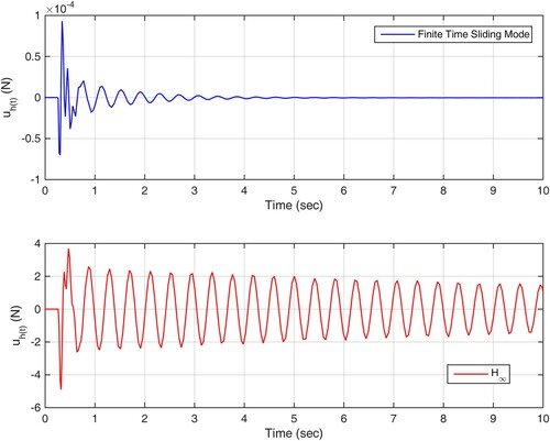
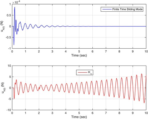
The simulation results are shown in Figures . Figure shows the suspension deviation due to sharp input disturbance under the two controllers. Also, tyre deflection and sprung mass acceleration are shown in Figures and , respectively. As it turns out, the proposed method reduces the suspension and tyre deflection to zero in less time, and the vertical acceleration shown in Figure indicates a better realization of the ride comfort target by the proposed controller. The control signal shown in Figure also expresses the fact that the backstepping fuzzy method achieves control objectives with lesser control effort than the method.
Figure 2. Suspension deflection in scenario 1.
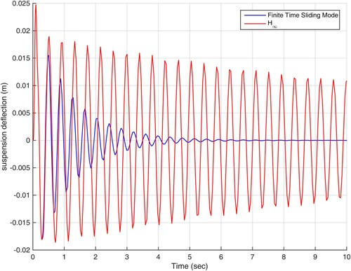
Figure 3. Tyre deflection in scenario 1.
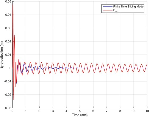
Figure 4. Acceleration response of the sprung mass in scenario 1.
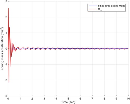
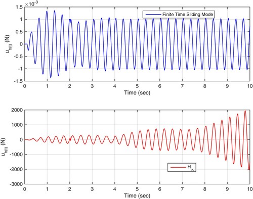
Figure 5. The trajectory of control efforts in scenario 1.
4.2. The second simulation scenario
This scenario is similar to the first scenario and there is only a time-varying delay in the hydraulic actuator as shown in Figure . The disturbance entered is in the form of Equation (23). The results shown in Figures state that under input disturbance and actuator delay, the control method is not able to maintain the stability of the suspension and its states tend to infinity while under the proposed method, tyre deflection, suspension and acceleration of suspension follow the optimal values. As shown in Figure , the goals set for the suspension system are followed with the least control effort.
Figure 6. Actuator time-varying delay profile used in the simulation.
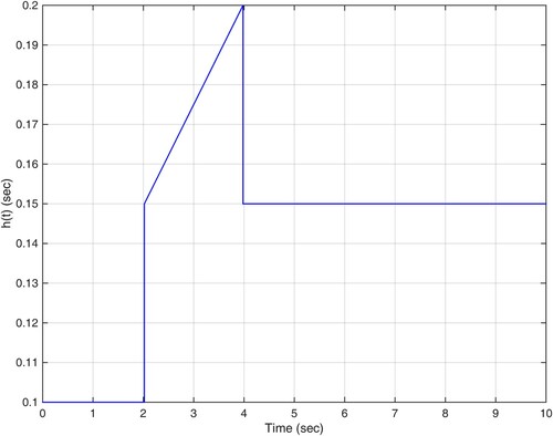
Figure 7. Suspension deflection in scenario 2.
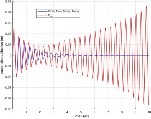
Figure 8. Tyre deflection in scenario 2.
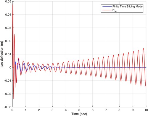
Figure 9. Acceleration response of the sprung mass in scenario 2.
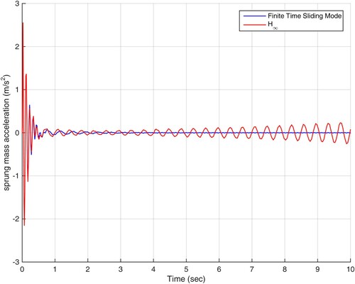
Figure 10. The trajectory of control efforts in scenario 2.
4.3. The third simulation scenario
In this scenario, the control actuator experiences a time varying delay in the form of Figure , and the rough road surface disturbances enter the suspension with the following equation:
(24)
(24)
The simulation results are shown in Figures and as can be seen from the figures, the control method is not able to achieve the control goals despite spending a very high control effort, while the proposed fuzzy backstepping method can achieve the goals set for the controller with the least control effort.
Figure 11. Suspension deflection in scenario 3.
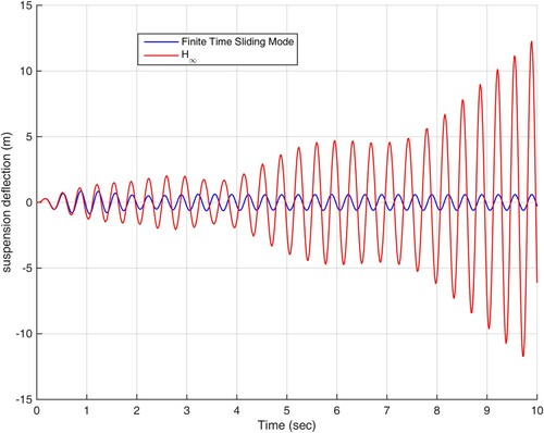
Figure 12. Tyre deflection in scenario 3.
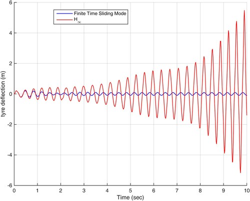
Figure 13. Acceleration response of the sprung mass in scenario 3.
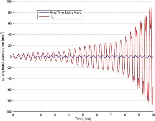
Figure 14. The trajectory of control efforts in scenario 3.
To better evaluate the performance of the proposed controller, the suspension deflection and tyre deflection error values based on the four criteria ISE, ITSE, IAE, and ITAE for the three simulation scenarios are given in Tables and , respectively. As can be seen from the perspective of these criteria, the proposed finite-time sliding mode method provides lower error values than the method. Although, the error comparison between the control methods used in the simulation does not fully reflect the optimal performance of the proposed method, according to the embedded control objectives, simulated scenarios and the results obtained in the figures and tables, as well as the capability and superiority of the suggested finite time sliding mode method is clear.
Table 1. The error values for suspension deflection (m).
Table 2. The error values for tyre deflection (m).
5. Conclusion
In this study, the ideal control of the suspension is studied. By using the backstepping and sliding mode control methods, the effects of non-linear terms, uncertainty, disturbance and time varying delay are covered. The realization of finite time control objectives is also shown in this system. In the proposed method, the backstepping control method is used to design virtual control signals and ensure stability, and the sliding mode control method is used to achieve finite time control goals and overcome the effects of uncertainty, disturbance and time-varying delay. The simulation results in MATLAB show that the proposed method can achieve the goals of riding comfort, road handling and minimizing the suspension deviation with minimal control effort. Developing a proposed method for systems with a more general working class could be a useful pathway for future studies.
Disclosure statement
No potential conflict of interest was reported by the author(s).
Additional information
Funding
References
- Li Z, Chen L, Nie L, et al. A Novel Learning Model of Driver Fatigue Features Representation for Steering Wheel Angle. IEEE Transactions on Vehicular Technology. 2021;71(1):269–281.
- Wang R, Ding R, Chen L. Application of hybrid electromagnetic suspension in vibration energy regeneration and active control. Journal of Vibration and Control. 2018;24(1):223–233.
- Bie Y, Ji J, Wang X, et al. Optimization of electric bus scheduling considering stochastic volatilities in trip travel time and energy consumption. Computer-Aided Civil and Infrastructure Engineering. 2021;36(12):1530–1548.
- Poussot-Vassal C, Sename O, Dugard L, et al. A new semi-active suspension control strategy through LPV technique. Control Engineering Practice. 2008;16(12):1519–1534.
- Cao J, Liu H, Li P, et al. State of the art in vehicle active suspension adaptive control systems based on intelligent methodologies. IEEE transactions on intelligent transportation systems. 2008;9(3):392–405.
- Amirifar R, Sadati N. A low-order H∞ controller design for an active suspension system via linear matrix inequalities. Journal of Vibration and Control. 2004;10(8):1181–1197.
- Yamashita M, Fujimori K, Hayakawa K, et al. Application of H∞ control to active suspension systems. Automatica. 1994;30(11):1717–1729.
- Cao J, Li P, Liu H. An interval fuzzy controller for vehicle active suspension systems. IEEE Transactions on Intelligent Transportation Systems. 2010;11(4):885–895.
- Gao H, Lam J, Wang C. Multi-objective control of vehicle active suspension systems via load-dependent controllers. Journal of sound and vibration. 2006;290(3-5):654–675.
- Chen H, Guo KH. Constrained H/sub/spl infin//control of active suspensions: an LMI approach. IEEE Transactions on Control Systems Technology. 2005;13(3):412–421.
- Du H, Lam J, Sze KY. Design of non-fragile H∞ controller for active vehicle suspensions. Journal of Vibration and Control. 2005;11(2):225–243.
- Bender EK. (1968). Optimum linear preview control with application to vehicle suspension.
- ElMadany MM, Abduljabbar ZS. Linear quadratic Gaussian control of a quarter-car suspension. Vehicle System Dynamics. 1999;32(6):479–497.
- Houzhong Z, Jiasheng L, Chaochun Y, et al. Application of explicit model predictive control to a vehicle semi-active suspension system. Journal of Low Frequency Noise, Vibration and Active Control. 2020;39(3):772–786.
- Goldhirsch I, Sulem PL, Orszag SA. Stability and Lyapunov stability of dynamical systems: A differential approach and a numerical method. Physica D: Nonlinear Phenomena. 1987;27(3):311–337.
- Chen H. A Feasible Moving Horizon Control Scheme for Constrained Uncertain Linear Systems. IEEE transactions on automatic control. 2007;52(2):343–348.
- Boyd S, El Ghaoui L, Feron E, et al. Linear matrix inequalities in system and control theory; 1994. (Society for industrial and applied mathematics).
- Nagarkar MP, Patil GJV, Patil RNZ. Optimization of nonlinear quarter car suspension–seat–driver model. Journal of advanced research. 2016;7(6):991–1007.
- Hassanzadeh I, Alizadeh G, Shirjoposht NP, et al. A new optimal nonlinear approach to half car active suspension control. International Journal of Engineering and Technology. 2010;2(1):78.
- Haris SM, Aboud WS.Multiple model adaptive control of a nonlinear active vehicle suspension. 2016 International Conference on Advanced Mechatronic Systems (ICAMechS). IEEE; 2016, November. p. 153–158.
- Du H, Zhang N, Lam J. Parameter-dependent input-delayed control of uncertain vehicle suspensions. Journal of Sound and Vibration. 2008;317(3-5):537–556.
- Li H, Yu J, Hilton C, et al. Adaptive sliding-mode control for nonlinear active suspension vehicle systems using T–S fuzzy approach. IEEE Transactions on industrial electronics. 2012;60(8):3328–3338.
- Vahidi A, Eskandarian A. Predictive time-delay control of vehicle suspensions. Journal of Vibration and Control. 2001;7(8):1195–1211.
- Jalili N, Esmailzadeh E. Optimum active vehicle suspensions with actuator time delay. J. Dyn. Sys., Meas., Control. 2001;123(1):54–61.
- Lei J, Tang GY. Optimal vibration control for active suspension systems with actuator and sensor delays. 2008 IEEE International Conference on Systems, Man and Cybernetics. IEEE; 2008, October. p. 2828–2833.
- Choi HD, Ahn CK, Lim MT, et al. Dynamic output-feedback H∞ control for active half-vehicle suspension systems with time-varying input delay. International Journal of Control, Automation and Systems. 2016;14(1):59–68.
- Li D, Ge SS, Lee TH. Fixed-time-synchronized consensus control of multiagent systems. IEEE Transactions on Control of Network Systems. 2020;8(1):89–98.
- Rostam-Alilou AA, Zhang C, Salboukh F, et al. Potential use of Bayesian Networks for estimating relationship among rotational dynamics of floating offshore wind turbine tower in extreme environmental conditions. Ocean Engineering. 2022;244:110230.
- Ma HJ, Xu LX. Decentralized adaptive fault-tolerant control for a class of strong interconnected nonlinear systems via graph theory. IEEE Transactions on Automatic Control. 2020.
- Zhao C, Liao F, Li X, et al. Macroscopic modeling and dynamic control of on-street cruising-for-parking of autonomous vehicles in a multi-region urban road network. Transportation Research Part C: Emerging Technologies. 2021;128:103176.
- Meng F, Wang D, Yang P, et al. Application of sum of squares method in nonlinear H∞ control for satellite attitude maneuvers. Complexity. 2019;2019.
- Sun W, Gao H, Kaynak O. Vibration isolation for active suspensions with performance constraints and actuator saturation. IEEE/ASME transactions on mechatronics. 2014;20(2):675–683.
- Barethiye VM, Pohit G, Mitra A. Analysis of a quarter car suspension system based on nonlinear shock absorber damping models. International Journal of Automotive and Mechanical Engineering. 2017;14:4401–4418.
- Mirabdollahi SE, Haeri M. Multi-agent system finite-time consensus control in the presence of disturbance and input saturation by using of adaptive terminal sliding mode method. Cogent Engineering. 2019;6(1):1698689.
- Du H, Zhang N. H∞ control of active vehicle suspensions with actuator time delay. Journal of sound and vibration. 2007;301(1-2):236–252.