
Abstract
In this paper we propose a metaprotocol-based architecture for the Internet of Things. The metaprotocol defines the message content, but it uses existing communication protocols and the forwarding capabilities of nodes that support this metaprotocol. Such nodes are described with a model that is demonstrated with a prototype middleware implementation. The behaviour of non-trivial nodes is defined with rules that specify actions for various events, including forwarding of received messages. In this way, a dynamic overlay network can be created with various possibilities of interconnecting and various node roles. Regardless of the roles a node possesses, communication with other nodes in this architecture is based on the same metaprotocol. The metaprotocol is based on SQL operations, which allows maximum flexibility in the design of a specific system. On the other hand, the proposed message encoding and the dependence on the underlying transmission protocols allow the creation of very short and simple messages, so that even the most resource-constrained devices can be included in such a system. A comparison with similar architectures shows the expected advantages of the proposed architecture when most resource-constrained nodes are used and when an arbitrary network configuration is required, different from the standard layered thing-gateway-server configuration.
I. Introduction
Internet of Things (IoT) is the name for a concept that starts from the idea that all things (that humans can use) should communicate, “think” and decide without human interference. This frees humans from doing everything that internetworked digitized things can do faster, easier, and better in their place [Citation1]. The field of IoT is being intensively developed today, and there are a variety of commercial environments implementing the concept [Citation2]. The beginnings of the development of the IoT date back to 1999 [Citation3].
Today, thousands of articles are published in the field of IoT, which proves the current intensity of its development, the spread of its application and the existence of a plethora of still unsolved problems [Citation4].
One of the problems with current research is that much of the solutions focus only on a variety of specific applications [Citation5], sometimes referred to in the literature as “connecting toothbrushes to the Internet” or “developing Intranets of Things rather than the Internet of Things” [Citation6]. Another problem is the large heterogeneity of IoT due to a large number (hundreds) of existing platforms that are not designed for interconnectivity but as separate ecosystems [Citation7]. Therefore, one of the challenges for researchers is to design a more flexible architecture that can be more easily used for any application in the IoT, and not only for a narrow set of specific problems. The flexibility should allow systems to be architecturally built based on the problem they are solving, rather than the other way around – by fitting the problem being solved to a predefined architectural pattern. The latter will usually lead to suboptimal solutions [Citation8].
The next problem is that the research often does not address security at all but defers it, as a problem that can be easily solved later [Citation9]. Embedding security mechanisms, especially privacy requirements, must instead be an integral part of the architecture and not an “afterthought”.
Perhaps the biggest problem with existing architectures is the complexity of building and using them [Citation10]. Most people do not know how to build computer systems, and those who do know have varying levels of knowledge. The complexity may discourage many users, who do not see value in an IoT system due to the complexity of building and using it in their domain. Initial expectations of massive IoT use may not yet have been realized precisely because of this problem.
This paper presents a new IoT architecture based on three principles. The first principle is to disregard the distinction between nodes representing things, gateways, and application nodes – any node anywhere in the system can take on any role if it is capable of doing so. The second principle is to describe a metaprotocol for data transfer between nodes. This metaprotocol can use any datalink-layer, network-layer or transport-layer protocols, and can even be used with only a physical layer. The basis of this metaprotocol are database operations from the SQL language, i.e. the SQL command SELECT and the corresponding data response. The third principle is the use of a specially designed configuration and a rule system that allows the integration of different nodes, from resource-constrained ones to advanced, into one system, with different connectivity between the nodes.
In this architectural description, the term “metaprotocol” is used. The metaprotocol, like the application protocol, uses existing underlying protocols for message transmission. However, to reach its final destination, a message may hop across multiple nodes. Some of these nodes may be ordinary network nodes (e.g. routers) and other metaprotocol-enabled nodes that can forward a message based on its content. In this way, the metaprotocol creates an overlay network that interconnects its nodes. A new underlying protocol is not proposed as there are already many IoT protocols on different layers and the creation of another such protocol seems unnecessary. The proposed metaprotocol can reuse many elements from the underlying protocol and only contain elements that are missing from that protocol. Therefore, it can be implemented over the simplest of protocols (e.g. serial connections) or over sophisticated protocols (e.g. HTTPS). It is this ability to use it over very different networks and protocols that distinguishes the proposed metaprotocol from other existing IoT protocols.
The proposed architecture was designed with simplicity of implementation and flexibility in mind. Nodes of different roles and complexity can be part of IoT systems based on this architecture, from the most resource-constrained thing to very complex nodes. With the proposed architecture, nodes can be assigned many tasks, such as transmitting sensor readings, requesting data from other nodes, responding to data requests, data processing, data storage, forwarding messages from other nodes, using the publish/subscribe mechanism either as a publisher or subscriber or both, and the like. Most of these operations are supported by the proposed metaprotocol, implicit node behaviour and rule system, and should simplify the implementation of any node. Nodes can form arbitrary networks, and each node can communicate directly or indirectly with any other node if there is a reason for such communication. The proposed architecture does not define or rely on a predefined network organization (e.g. a tiered one), does not require a centralized node, and can be used to create arbitrary networks, with mutable connections, even with moving nodes. This makes this architecture very flexible.
Security in the proposed architecture is based on reusing existing security services, i.e. using what is already there, namely proven security services of the underlying transmission (transfer) protocols. If these services are not sufficient, an additional mechanism, proposed in the metaprotocol, can be used. Whether the services of the underlying protocol or those of the metaprotocol are used can be determined with implicit or explicit rules within a node.
The original contribution of this paper is a new IoT architecture here defined with a system model, a node model, a communication metaprotocol, and a middleware implementation. The main advantages of the proposed architecture include the ability to easily incorporate resource-constrained nodes into the system, define the nodes’ tasks through rules, and create an arbitrary centralized or decentralized network system.
The remainder of the paper is organized as follows. In Section II, the related work is elaborated. In Section III, the model of the system is presented. In Section IV, the system is showcased on a use case. In Section V, usage guidelines are laid out. In Section VI, advantages of using the proposed system are discussed, as well as some disadvantages. Finally, in Section VII, the conclusion and future work are given. The Appendix holds a few example scenarios with implementation details.
II. Related work
Currently, a few protocols are mainly used in IoT [Citation11]. At the datalink layer, the most commonly mentioned protocol is Bluetooth and its version for resource-constrained systems called Bluetooth Low Energy (BLE), which solves the problems of energy consumption, master-slave architecture, and required processor power. The BLE protocol has eclipsed other protocols in this layer, such as IEEE 802.11 (Wi-Fi) and its revision called IEEE 802.11ah, which addresses power consumption. The IEEE 802.15.6 protocol is also not widely used, nor is IEEE 802.16 (WiMAX), although these protocols are sometimes mentioned as suitable for the IoT [Citation11]. Within the category of low-power wide-area (LPWA) protocols, LoRaWAN and SigFox [Citation11] have found a somewhat larger audience.
The datalink-layer protocol IEEE 802.15.4 (called 154 for short in the text) [Citation12] is used as the basis for ZigBee [Citation13], a popular solution for local networks, and for the Thread protocol stack [Citation14]. Thread is also based on the 6LoWPAN protocol [Citation15] for encapsulating the IPv6 protocol. Another popular protocol stack of this capacity is Z-Wave [Citation16], based on proprietary protocols. ZigBee and Z-Wave are only designed for communication in a local IoT network. Thread also assumes the existence of a router, but considering 6LoWPAN, this router only needs to perform protocol conversion, and does not need to have a control function. On the network and transport communication layers in the global network, common protocols are used (IP, IPv6, TCP, UDP).
At the application layer, CoAP (adapted from HTTP) [Citation17], XMPP [Citation18], MQTT [Citation19], AMQP, and RESTful-based protocols are commonly used [Citation20]. They all use the publish-subscribe model, i.e. they all create client-server architectures and define communication mechanisms, but they do not define node operations as the proposed architecture does.
In [Citation21], devices can communicate via REST using multiple protocols at the datalink layer. They can receive certain data and be asked for certain data. The user must learn the rule language, which is later compiled into the Java programming language. In [Citation22], the rules are written in the Lua scripting language using a semantic engine API. The engine can communicate with devices through its protocols and make conclusions based on ontologies. The rules are edited using web configuration.
In [Citation23], users can create smart objects by selecting their shape, parts and behaviours through a graphical interface. The behaviours consist of rules that control parts of the objects, which have some ready functionality and are then compiled in Java. The rules are of the type “when <some reading> do <some action>”. In [Citation24], rules are created using a graphical interface to compose provided services. The services are based on data collected from things, data sent to things, and metadata derived about things. Things are also abstracted through a representation layer.
In [Citation25], there is a system that uses HTTP or an HTTP gateway to communicate with things that use REST. This creates what is often called a Web of Things (WoT) on the local network. Rules are written in JavaScript and the description of their triggers is written in JSON format. They can refer either to data from things or to existing data, and generate events for a module that performs activities that can also be monitored in real time. In [Citation26] a system for graphical creation and modification of rules is presented, implemented in JavaScript and jQuery technology. The system works with a rule engine that can receive events, store data and execute actions. The engine communicates with smart things using various protocols.
In [Citation27], triggers of different levels of abstraction can be defined using context information about an ontologically based representation of devices classified by categories and their services classified by capabilities. The system is used to automatically create an appropriate graphical interface in one of the authors’ projects and to propose rules to the user in another project. In [Citation28], existing rules of a given system are analyzed and described using formal models. Then, when a new device is connected to the system, it can use the mappings learned there to analyze its functionalities, automatically create rules and recommend them to the user.
In [Citation29], gateways store timestamped data from devices. Devices are abstracted by their so-called “avatars”, which are described with ontologies. Higher layers can send queries to the gateways using the gateways’ query language and the gateways can respond. In [Citation30], Event-Condition-Action (ECA) rules are created using a graphical editor that corresponds to the system's rule language, which are then compiled into another rule language. The cloud on which the system is installed receives data from things that use the local networks. Then it can push actions to an application that connects to the cloud.
Further comparisons with the above solutions are presented in more detail in Section V, after the proposed architecture is presented.
III. System model
The system model is defined by its nodes, their connectivity, and their operation.
An essential part of the system are “metaprotocol nodes”, i.e. nodes that actively use the metaprotocol. Depending on their role, such nodes can be very simple (resource-constrained nodes) that can only send or receive simpler metaprotocol messages, or they can be more complex. For example, in addition to its original function of using its sensors and/or actuators, a node may also be used to forward unmodified messages, or modify messages before forwarding them, possibly using a different underlying transmission protocol. Another node may be even more sophisticated, using rules to manipulate, store, retrieve messages, perform operations on a collection of messages, use security features, etc. These node complexities can be related to RFC 7228 [Citation31] and its classes. When the most resource-constrained nodes are mentioned, they can be considered as Class 0, but in this architecture, the modelled metaprotocol nodes can be Class 0, 1, 2, or “above”. The complexity of a node does not affect its metaprotocol communication, only the operations it supports.
The second node type is the “user node”, which may not be aware of the metaprotocol but is a part of the system, e.g. via a web interface provided by nodes actively using the metaprotocol (as in the prototype implementation).
Finally, the last node type is the “network node”, which is simply a part of the network infrastructure (routers, gateways, switches) and as such serves to provide connectivity on the respective network without being aware of the metaprotocol it enables.
Two nodes can be connected (exchange messages) in several ways:
via a direct physical connection using the underlying protocols with a metaprotocol message in the payload
via another metaprotocol node forwarding the original or modified message
via a network node that does not use the metaprotocol with its message in the payload
via multiple nodes, all, some, or none metaprotocol nodes.
Figure illustrates an example system based on the proposed system model, which consists of metaprotocol nodes (square), user nodes (diamond shape), and network nodes (circle).
Figure 1. A system example with various nodes and connections.
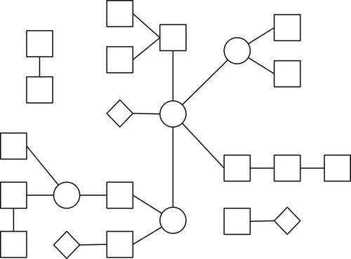
Normally, in such a system, any node can be connected to any other node as needed. However, there may also be isolated nodes that indirectly participate in system operation through changes in the system environment. For example, their sensors may detect changes that are effected by other nodes and vice versa.
Only the metaprotocol nodes define the system behaviour. In the following text, only these nodes are described, and the term “node” stands for such a node.
The metaprotocol is defined by its messages and the behaviour of the nodes. Several message types are defined, mostly based on the SQL SELECT command and its data response, each type representing a particular operation in the model of IoT systems. The main purpose of messages is to enable communication between nodes that produce data (usually called “things”), nodes that process and store data (“servers” or “clouds”), and nodes that request this data for a specific purpose (“clients” or “users”). In addition, the proposed model includes the usual publish/subscribe mechanism.
In the proposed system model, there are no standard node categories, since each node can take the role defined for it, e.g. the role of a thing, a server, a client, a gateway, or a combination of roles. A generic node model is presented whose behaviour is controlled by its software, node settings, and capabilities. The standard architecture model (thing-gateway-server-client) can be realized by the proposed model, but other arbitrary models can also be created.
A. Node model
Each node in the proposed system model has a role that defines its behaviour. For very resource-constrained things, this behaviour can be simply described as “collect and send the sensor value”. On the other hand, a node in the cloud can collect data, process it, combine results from different sources, and control complex operations. Such extreme node cases require custom programmes – in the first case a very simple programme, in the second case a collection of multiple programmes and services. However, the focus in this subsection is on other types of nodes that are not among the most resource-constrained ones and are also not extremely complex. Such nodes can be modelled in terms of a few operations that they perform periodically or in response to sensor input or a received message.
The node that controls some devices (actuators) or collects readings from a connected sensor can be modelled as an activity “every X time units do THIS” or “on event Y do THIS”. The operation “THIS” may include reading the sensor, sending a command to the attached actuator, storing the obtained value locally, sending some data to a remote node, etc. These operations can be broken down to simpler actions that can be described with a few parameters. Such breakdown is used in the proposed node model.
Another part of the node's behaviour are the actions related to the message exchange. What is to be done when a message is received? Should the node store it, forward it, discard it, or perform a local action on it, e.g. “read sensor”, “send command to device”, etc.? Sometimes an additional action may be required when sending a message, such as “save a copy”, “send to a backup node”, “update something”, etc. The previously described behaviours can be modelled with “triggers” that are evaluated for each message that is received or to be sent.
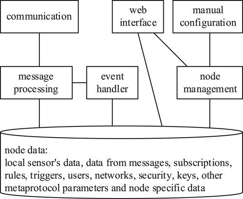
The proposed node model is shown in Figure . It includes operations that can be triggered periodically, then when a local event occurs, and finally when messages are exchanged. Triggers can be defined with rules, as described in Section V.
Figure 2. Node model.
B. Node middleware
The model of the middleware prototype implementation is shown in Figure . The basic components are a main programme and underlying protocol modules, UPMs. The UPMs can use any underlying protocol. E.g. the node in Figure has 4 UPMs, one for TCP, one for UDP, one for BLE, and one for 154. These UPMs enable the proposed metaprotocol to be used over other protocols by using protocol encapsulation and decapsulation, and extraction and injection of information from and into the headers of the underlying protocol. The UPMs use the node's network adapter(s), directly or through other layers (protocols), to communicate with other nodes.
Figure 3. Software architecture of middleware implementation.
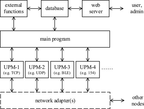
The main programme relies on a database that can contain stored messages, subscription triggers, rules, node configuration, user list, etc. A database can be used directly or through externally programmed database functions. This should be sufficient for general node operations, using sensors, receiving messages, processing messages, sending messages, and forwarding.
If a node is to allow direct interaction with users, an additional web server should be integrated. Through its web interface, common users and administrators can retrieve the desired information, send commands to the nodes, and perform similar operations. In the prototype implementation, the users can use the web interface to access raw data, inject or manually send messages, manipulate rules and configuration, etc.
For more resource-constrained nodes, without a web interface, the configuration must be set manually (imported into the database) if the default behaviour is not sufficient. If a node is even more resource-constrained, it will not use a database at all so everything must be programmed into the main programme, as shown in Section V.
The node model and implementations are modular – modules that are not required, such as the web server, database, or some UPMs can be removed from many nodes, reducing hardware requirements.
The proposed message formats and types with their purpose are described next, followed by the rest of the node activities.
C. Messages
The proposed metaprotocol does not define its underlying transfer protocol – its messages can be transferred over any available underlying protocol. However, facilities provided by the underlying protocol can be used to simplify the metaprotocol's message by omitting already provided elements.
The message types, message elements and their encapsulation into the underlying protocol are shown in Figure . A single message may contain the following elements, in this order:
HD – message header (1 byte);
ID – message identification number (1 byte);
LEN – payload length (2 bytes);
DST – EUI-64 destination node id (8 bytes);
SRC – EUI-64 source node id (8 bytes);
PL – message payload (varying length);
CRC – message checksum (4 bytes).
Figure 4. Protocol format and encapsulation.
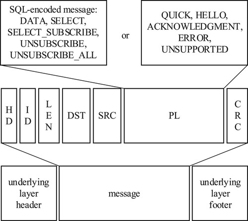
Not all elements are required in all messages. For example, if the source/destination node identifier can be extracted from the underlying layer (e.g. if the protocol carries EUI-64), these elements can be omitted from the message; CRC may only be required if the underlying protocol (e.g. a simple physical layer) does not provide similar protection. In some short messages, all or almost all elements can be omitted.
The header consists of 8 bits that specify which elements are included in the message (bits I, L, D, S, R for ID, LEN, DST, SRC, CRC) and which optional operations are required from the message receiver, namely: returning an acknowledgement message (bit K), securing the message for confidentiality (bit C) and securing it for authenticity (bit A).
The identifiers used in the metaprotocol are therefore EUI-64 identifiers of the respective node. Almost every metaprotocol node has at least one of them by itself, since many datalink-layer protocols (BLE, 154, Ethernet, Wi-Fi …) use them anyway, and some network layer protocols (IPv4, IPv6 …) may make use of them as well. Some protocols use EUI-48, which can be easily converted to EUI-64, and others use even shorter addresses, which can be even more easily converted to a unique 64-bit representation.
The message ID together with SRC and DST forms the message identification and is used to confirm that the message has arrived, to notify an error in the message, to notify an unsupported operation in the message, and to detect duplicates, such as when the same message arrives at a destination via multiple routes.
In the following protocol description, mostly only the message payload is described.
1. SQL encoding
In order to make this metaprotocol as suitable as possible for resource-constrained devices, great effort has been made to make it extremely lightweight, both in terms of message size and the encoding/decoding process. Elements that can be extracted from the underlying protocol can be omitted from the message. For some message types, encoding can be used to further reduce the length of the payload. The type of a received message can almost always be decoded from only the first character of the payload. Also, most resource-constrained nodes may support only a few simple operations (or only one) and ignore received unsupported message types.
The message payload formats are inspired by SQL commands. These commands can be partially encoded to reduce message size, using an 8-bit binary value from the ASCII 128–255 range for the most commonly used SQL SELECT keywords. For example, the SQL query “SELECT a, b, c FROM table WHERE a > b AND b > c ORDER BY c;” can be encoded as “X1a,b,cX2tableX3 a>bX4b>cX5X6c”, where “Xi” are the corresponding 1-byte code values for the replaced keywords. With such an encoding, the message payload size is significantly reduced, e.g. from 59 to 24 bytes for the given example.
Theoretically, any SQL SELECT query can be requested in the message. However, since this metaprotocol is designed for IoT environments, some of the SQL syntax has been simplified to facilitate the most commonly used operations. Additionally, the default table and column names are used if they are not directly specified in the SQL query.
The default table name is formed from the source/destination node identifier prefixed by the character “t”, as in “table”. Whether the source or the destination identifier is used depends on which node is providing the data: when sending data, the source identifier is used; when requesting data, the destination identifier is used. E.g. if a node with “source id” = 0×1111111111111111 sends data, the default table name on the destination node (which will store the data) is “t1111111111111111”. Similarly, if a node with “destination id” = 0×2222222222222222 requests data from another node, the default table name is “t2222222222222222”.
If the column name for a message with a single value is not specified, the name “d” (as in “default”) is used. If a message contains multiple values, default names are “d1”, “d2”, “d3”, etc.
Tables containing data received from other nodes must also contain, in addition to the columns specified in the message, a default column “t” – a timestamp of the message data, that is, when it was created or received.
Different messages can be classified into several message types according to their payload:
DATA;
SELECT, SELECT_SUBSCRIBE;
UNSUBSCRIBE, UNSUBSCRIBE_ALL;
QUICK;
HELLO;
ACKNOWLEDGMENT;
PAYLOAD_ERROR;
OPERATION_UNSUPPORTED.
2. Message type DATA
DATA messages are usually sent by nodes that generate data (like sensors) or in response to a SELECT query. A DATA message contains some data (readings, status, a reply to a data request, a reply to a subscription, etc.). A DATA message can contain a single named value in the form:
name=value;
name1,name2, … ,nameN=val1,val2, … ,valN;
name1,name2=val11,val21;val12,val22;
val11,val21;val12,val22;
A node that merely stores received DATA messages in the described tables must first expand a message into a SQL INSERT query and then execute it. The table implicitly used in this query has the default name consisting of the letter “t” and “source id”.
3. Message type SELECT
A retrieval of data from a node is requested by a SELECT message. The SQL SELECT query can be a simple query such as “SELECT col1, col2 FROM table;” or more complex with aliases, a WHERE, and other clauses and conditions. When data is requested from a sensor node, the query can be even simpler, e.g. “SELECT val1, val2;”, or “SELECT *;” – or even “X1*” when encoded.
The result of the SQL query is usually packed into a DATA message and returned to the requester.
4. Message type SELECT_SUBSCRIBE
SELECT_SUBSCRIBE is intended for the publish/subscribe service, where, after receiving some data from its sources, the service provider sends the appropriate data to its subscribers.
The message SELECT_SUBSCRIBE is an extended SELECT message that contains the suffix “SUBSCRIBE id” at the very end, before the last “;”. A node providing such a service must save this SQL request as a “subscribe request”, identified by the given “subscribe id” and “source id”. When a SELECT_SUBSCRIBE is received, the SELECT query it contains shall be executed and stored. Later, when new data is inserted into the tables mentioned in the SELECT_SUBSCRIBE message, the SELECT query should be executed again on the updated tables and the difference from the previous SELECT result, if any, returned to the client.
5. Message type UNSUBSCRIBE
An UNSUBSCRIBE message is intended for cancelling a subscription. The message contains only the keyword “UNSUBSCRIBE” and a subscription id. The receiving node shall delete that subscription from its tables.
6. Other message types
An UNSUBSCRIBE_ALL message is the same as the UNSUBSCRIBE message, except that it contains the keyword ALL as the “subscribe id”. The receiving node should delete all subscriptions of the sending node in its tables.
A simpler DATA message, called QUICK, contains only a one-byte value in the payload. All other message elements, even the header, can be omitted. Therefore, the shortest QUICK message can have a one-byte length in total. Such a message is intended for resource-constrained things where only very short messages are feasible.
A HELLO message has no payload at all. Since all other message elements can be omitted, a message of this type can also be very short, even zero-bytes long. This message type is intended for notifications or status requests (“I am online”) and should usually be sent periodically, or when a node comes online, or it is available for message reception, e.g. for nodes that are not always online.
An ACKNOWLEDGMENT message is used to notify the sender of a previous message that the message was received and understood. The message payload contains “K<1-byte message id>”, and, together with SRC and DST reversed from the original message, it identifies the message for which this is the acknowledgement. This message is usually sent when the K-bit had been set in a previously received message.
A PAYLOAD_ERROR message is sent when there is an error in the received message. The message is in the form “P<1-byte message id>” and identifies the troubled message with the given identifier. It may be followed by an optional error description, e.g. “P\x33Malformed payload”.
An OPERATION_UNSUPPORTED message is sent when there is a processing error in the received message, caused by an unsupported operation in the destination node. The message is of the form “O<1-byte message id>” and it identifies the troubled message with the specified identifier. An optional description string may follow the identifier.
D. Security actions
The proposed system allows the use of the underlying protocol's security services when they are available, but also provides mechanisms when they are unavailable or insufficient. In the following text, the security options of the metaprotocol are first described, and then the way they can be combined with the available security services of the underlying protocols through implicit and explicit rules.
In the context of this metaprotocol, security consists of confidentiality and authenticity. Confidentiality is realized by encrypting the message, while authenticity is realized by a digital signature. A node sending a message defines the necessary security components by setting flags C for confidentiality and A for authenticity in the message 8-bit header. Other nodes involved in the message transfer must meet the security requirements defined for the message by using the underlying services or the services provided by the metaprotocol, or simply not forward the message if they cannot. The public key cryptography is used for the key scheme. In the implementation of the metaprotocol, AES-192 with CBC is used for symmetric encryption and RSA-2048 with SHA-256 is used for asymmetric encryption and signing. The key exchange is not a part of the proposed metaprotocol – it is assumed that the keys are inserted into the nodes by some other method, either by complex rules built over the metaprotocol, or manually.
If only the C flag is set in the message header, only the confidentiality is requested. The confidentiality is achieved by a digital envelope. A digital envelope of the original message has the following format in the payload:
one-byte character @;
two-byte length of the encrypted message;
original message, symmetrically encrypted;
two-byte length of the encrypted secret key;
asymmetrically encrypted key;
initialization vector (24 bytes for AES-192-CBC).
Using the digital envelope, the entire original message can be encrypted, including all elements, not just the payload, and placed as the payload into a new “carrier” message. In this way, even the message identifier, the original source, and the final destination can be hidden from nodes that only forward this message. If this is not required, depending on the original message or the rules, only the header and the payload can be encrypted, since, after decryption, the original message can be reconstructed with elements from the “carrier” message.
The symmetric encryption key and the initialization vector are randomly generated. The public key of the destination node is used for the asymmetric encryption.
If only the A flag is set in the message header, only the authenticity is requested. The authenticity is achieved by a digital signature. A digitally signed message has the following format in the payload:
original message payload;
one-byte character #;
hash of the entire message, asymmetrically encrypted (sender's private key).
When both flags A and C are set, the message contains both a digital envelope and a digital signature of the message. A digitally enveloped and signed message has the following combination in the payload:
character @;
rest of the envelope (parts 2–6);
character #;
rest of the signature (part 3).
When processing messages in the rule system, the flags ENCRYPTED and SIGNED are used, together with the special commands ENCRYPT, DECRYPT, SIGN and VERIFY.
When communication takes place in a closed system where all nodes are trusted, security is not mandatory, and a message can be sent unencrypted and unsigned, as is the case in many systems today. This is especially the case for things on a local network that may be physically separated from everything else. However, once the message crosses such boundaries and is forwarded to a destination over an unsecure network, it is necessary to ensure at least some minimal security requirements, e.g. by signing the message, to prevent the introduction of message forging.
Given the very likely processing limitations of some IoT devices related to cryptographic algorithms, the metaprotocol allows these devices to request security “by proxy” even if they cannot provide it. For example, this security may apply only to the time after the message has left the local network.
A node can decide what to do with a message based on implicit rules (presented later in this section) or additional (explicit) rules defined specifically for that node. For example, with the additional rules, a node can check where the message came from and decide what to do next based on that. After considering the implicit rules that arise from the basic ideas of the proposed architecture, common additional rules are also considered.
Resource-constrained nodes can be configured to not use security, but simply trust everything and forward all received messages unchanged, helping a message from a more distant thing reach a smarter node (e.g. a gateway). The smarter node can analyze the message from a security perspective and secure it appropriately as it is forwarded. To do this, it can use services of the underlying protocol layer or the capabilities of the metaprotocol, or both.
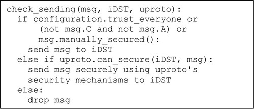
The implicit security-check rules are represented with an algorithm shown in Listing 1, which uses Python-like pseudocode. The argument msg is the message to be transported, iSRC (immediate source) is the underlying-protocol address of the previous node in the transmission, iDST (immediate destination) is the underlying-protocol address of the following node, and uproto is the underlying protocol.
A resource-constrained node can be configured to forward any message it receives. A smarter node should check flags A and C in the message header and, if they are not set, forward the message. If the flags are however set, but the message is already protected by the security mechanisms of the metaprotocol, the message should also be forwarded. Otherwise, the message will be dropped unless the underlying transmission protocol can provide the required security mechanisms.
Listing 1. Implicit security checks before sending a message.
Listing 2. Implicit security checks upon message reception.
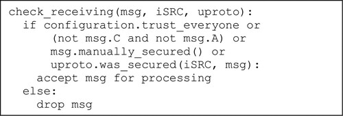
Security checks should also be performed when the message is received. The algorithm for implicit checks at the message reception is shown in Listing 2.
The second part of the security mechanisms are explicit message rules that should normally be activated when a message crosses the network boundaries. For example, consider a system in which a gateway connects the trusted local network and the untrusted global network. A rule in the gateway might specify that a message without C or A received by a node in the local network and headed to a remote node (in the global network) should be dropped. A similar rule should be established for received messages from the global network. Another rule can enforce encryption and signing of a received unprotected message from the local network if flags C and A are set in the message. A complementary rule decrypts and verifies a message received from the global network before forwarding it to a local network node. For example, trusted and untrusted networks can be distinguished by protocol – a local protocol can be trusted (e.g. BLE) and a global one can be untrusted (e.g. TCP).
E. Message routing
The message ID is randomly generated the first time a message is created for a given destination node. On the next message from the same node for the same destination, this ID is incremented in modulo-256 arithmetic. This mechanism can be used to detect duplicate messages. In a local network, duplicates are expected when a message is broadcast from the starting node toward the destination node, using other nodes as carriers. Here, since ID, SRC and DST are used as the complete message identifier, the duplicate messages can be easily detected in the short period of time for which the message identifiers are stored.
A message sent from one node to another may traverse different paths at different times or even simultaneously. When sending or forwarding a message, a node may have several alternate routes for the next node. A single next node can be selected or a message can be sent to all alternatives. To optimize network usage, a smarter node should track the reachability of the destination node over each route and dynamically update this information for future use.
The most resource-constrained nodes like the Class 0 should not have complex routing and can use broadcast at the underlying layer. When a resource-constrained node receives a broadcast message that is not intended for that node, it can drop or forward that message. When using broadcast, some security features must be turned off – some message elements must be visible to all to allow forwarding. However, the message payload may still be encrypted and/or signed for the destination node.
IV. Use cases
In this section, an example IoT system is used to demonstrate the benefits of the proposed architecture in terms of system design, facilitated inclusion of very resource-constrained things, and usability and flexibility. Additional examples with more details on the messages can be found in Appendix A.
An example system shown in Figure is modelled for a smart farm with animals, e.g. cows, sheep or the like. The IoT part of the system consists of devices (things) embedded in collars worn by the animals, in water stations, feeding stations, gates, beacons, an animal processing station (e.g. milking station), a server node and user applications.
Figure 5. Example IoT System.
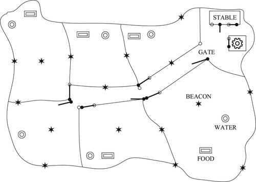
In this example, the farm consists of large land areas where animals can roam, eat, rest, sleep, etc. The land is divided into these areas which are accessible through fenced corridors controlled by smart gates. The idea is to automatically direct the animals to selected areas each day. Smart water and feeding stations are placed in some areas, where necessary and possible. Beacons are also placed on some fences and other farm objects to monitor the animals’ movements.
The smart gates receive commands from the server – DATA messages with “action=‘open’/’close’/‘status’” – and need a long-distance connectivity to do so, at least sometimes, e.g. once an hour. A smart gate node does not only control the gate, but also records which animal has passed through it. A smart collar on an animal periodically sends a HELLO message. When a gate receives such a message, it extracts the identifier of the collar and stores it locally along with the current timestamp. Later, when a connection to the server is established, the gate sends all buffered data to it, as one or more DATA messages, in the form “time,animal_id=t1,id1; t2,id2; … ;”. Alternatively, if no remote connection is available, the gate can be programmed to open and close at specific times of the day.
The smart nodes at beacons, gates, water, feeding, and processing stations periodically broadcast their locations, implicitly via their identifiers, through a DATA message “location=<node_id>;”. A smart collar that receives such a message saves it for later retrieval at the barn gates, that ask for them with the message “SELECT *;”. If a more detailed real-time animal tracking mechanism is required, more smart nodes with long-range connectivity can be distributed on the farmland. For example, some beacons, water and feeding stations could be equipped with such more advanced nodes. For even more accurate tracking, some collars could be equipped with a smarter node with a GPS sensor that tracks nearby animals through their HELLO messages, and sends this data to the server periodically, or only when specifically requested by the server with a “SELECT *;”.
The smart water and feeding stations detect the presence of nearby animals via their HELLO messages. When an animal is detected, the station should use its sensors to check the availability of food or water and provide more if needed.
The presented system is loosely connected. Adding a node sometimes requires no any changes to any other nodes in the system, except perhaps in the server node. For example, if a new beacon is placed somewhere, its location should be entered into the server and no other changes are required. The same works for gates, stations and collars. If a node is removed, no change is required to any other node. The behaviour shown earlier for different nodes can be easily programmed before the node deployment. Some nodes are very resource-constrained (e.g. beacons) and can be implemented with some very resource-constrained microcontrollers like the Class 0 devices. A node with a new or a changed role can be easily introduced into the system without requiring system-wide intervention or any change at all. For example, the status of water and feeding stations can be transmitted by (some of) these stations simply by appending a resource to the message they already send as a part of the location messages. For example, such a message may look like: “location,water,battery=‘w421’,73,45;” conveying not only the location identifier (“w421”), but also the water tank status (73%) and battery status (45%). The collar that receives such a message simply stores it as-is (e.g. implicitly extended table with new columns), and later passes it on request – a change is required only in the node that provides this additional information, and probably in the server node that can use it (otherwise this new information is only stored and not used).
All collected data can be stored on a single (remote/local) server, or the data can be delivered to multiple servers. Therefore, control can be defined in one or more places. For example, data from feeding stations can be delivered to the server of a company that manages farm supplies. However, this information will be also available to the farmer so that he can analyze the food consumption at the different stations and determine, for example, where there is enough vegetation and where to send his animals. On the other hand, several farms, even with different owners, can be controlled by the same server (or several).
Security is not considered so far because there are no critical problems presented. However, if nearby areas are used by other farms with their animals and a distinction between them must be made, various other mechanisms can be used.
If only object discrimination is sufficient, it can be implemented almost entirely by data filtering in the servers. Water and feeding stations could be optimized and given a list of animals for that farm (or filtered on identifiers) so that they are not activated when only foreign animals are nearby, i.e. outside the fences but within communication range.
If this is not sufficient, other security mechanisms must be used. If security can be achieved by the lower-layer transfer protocol, that would be optimal: it places the least demands on the node's processing capabilities. For example, if a shared secret is used on this communication channel, all nodes can be configured for it before deployment. If this is not enough, and there is a suspicion that a node in such a network might be compromised, more sophisticated methods can be used, e.g. using digital envelopes and/or digital signatures provided by the metaprotocol or a more secure underlying protocol. Using these methods would then require public and private keys for all nodes and public key distribution. Each message can then be authenticated and only the valid messages are processed.
V. Implementation options
A. Simplified application design
In the subsection III.B, the node model is presented. Building on this, this section describes other middleware capabilities that can simplify node implementation. Like the TCP and UDP protocols provided by the network layer in operating systems, the proposed middleware can provide message manipulation operations (creation, verification, data extraction, sending, receiving, rule processing …).
For devices with very limited memory, the use of an advanced middleware, such as the implemented prototype, might be too demanding. Such devices might need only a small subset of the operations, support only some message types when sending and receiving, no support for encryption, etc.
Devices with more memory, but not enough for the full middleware, can use only some elements of the middleware in a custom programme. For example, a resource-constrained device that reads its sensors, and sends the readings to the default gateway every hour or on explicit request, could be programmed with the following pseudocode:
program
register_event(ON_MESSAGE, on_message)
loop
default_send(read_sensor())
delay 1 hour
on_message(message)
default_send(read_sensor())
The operations register_event and default_send should be provided by the included middleware parts.
Devices with sufficient memory could use more middleware elements to simplify application development, e.g. as in prototype implementation or the like. Such middleware should be able to perform the operations required by the device for most use cases without the need for an additional application. All required behaviours (for most use cases) can be defined through the node configuration using rules. Basic rules can be classified into periodic rules, on-message-reception rules, on-message-sending rules etc. A basic set of actions can include reading a sensor to a file or a table, writing a value to a peripheral device (e.g. an actuator), sending data to the default node or a specific one, some actions on a sensor event, on message reception, and the like.
Rules can be defined via editing the rule table in SQL, or a graphical interface as in the prototype implementation. In the following descriptions, a textual representation of the implemented interface is used because it is more descriptive and simpler.
A device like the previous one, but implemented with the described middleware, can have the following configuration:
RULE 1:
type=PERIODIC
period=3600
action:
READ_SENSOR (TEMP_25, TABLE_0)
SEND_DATA (DEFAULT_GW, TABLE_0)
RULE 2:
type=ON_MESSAGE
FILTER (MESSAGE.type == MSG_TYPE_SELECT)
action:
READ_SENSOR (TEMP_25, TABLE_0)
SEND_DATA (MESSAGE.from, TABLE_0)
RULE 3:
type=ON_MESSAGE
FILTER (MESSAGE.type == MSG_TYPE_HELLO)
FILTER (MESSAGE.flags & MSG_FLG_ACK != 0)
action:
SEND_DATA (MESSAGE.from, EMPTY_MESSAGE)
The same middleware for advanced nodes (e.g. gateways) could have more message filtering and forwarding capabilities by using the database with information about sensor nodes: which nodes to forward messages from and where to forward them to. The following sample configuration can be used in such a node.
RULE 1:
type=ON_MESSAGE
FILTER (SQL_CHECK_FORWARD_FROM (MESSAGE.from))
FILTER (SQL_CHECK_FORWARD_TO (MESSAGE.dest))
action:
RUN_SQL (“SELECT real_dest FROM table_fwd
WHERE from_id =“ + MESSAGE.from, RESULT_0)
FORWARD_MESSAGE (MESSAGE, RESULT_0)
B. Architecture implementation guide
A guide for implementing the proposed architecture is shown in Figure with a UML activity diagram.
Figure 6. Architecture implementation guidelines.
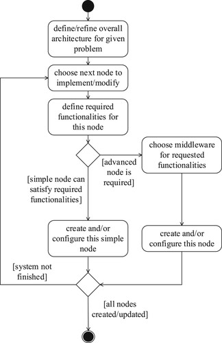
If a new system is to be created, an overall system architecture should be defined first. Otherwise, an existing architecture can be used instead, possibly with some refinements. Next, elements are added or updated. For resource-constrained nodes (“things”), simple programmes can be used. Advanced nodes should use middleware, e.g. like the one presented and implemented in this paper, which can be configured with implicit and explicit rules. The process is repeated until a satisfactory system is created. The same implementation model can be used for existing systems when nodes are added or the behaviour of a node is changed. Changing only one node should require little or no changes to other nodes, since the implicit behaviour of the metaprotocol can suffice in most cases. In this way it is similar to the Internet: when a new computer connects it should get its IP address, and no further changes are required for other computers and devices already on the Internet.
VI. Discussion
The behaviour of the proposed architecture is mostly based on a rule system, with implicit and custom rules. However, there are some differences with similar systems cited in Section II.
Some of those systems ([Citation23,Citation30]) are designed for a specific purpose only (here – home automation, sports training). Many of these systems require the user to learn a specific language in order to use them (partially [Citation21] and [Citation22], fully [Citation25,Citation29]). All of these systems (except [Citation22] to some extent) can only be used on local networks. Next, all of them require an additional abstraction layer between the devices and the system, the layer that converts data into messages and vice versa. All of the cited systems (except [Citation21] to some extent) have strictly separated node categories (e.g. sensors, routers, servers). None of the previous systems allow dynamically changing the role (and complexity) of a node by only changing its settings. The insertion of a node initially having only simple operations, which then gradually becomes more complex, is not possible in any of these systems.
The proposed architecture, on the other hand, is not designed for a single purpose, but for general-purpose IoT systems. Since SQL is used for message formation, there is no need to learn an additional programming language used only for that system. In further development, an interface can be created that automates rule generation and uses only data operations that are understandable to the ordinary users. The messages of the proposed metaprotocol cross over different networks and protocols unchanged, and there is no need to create an additional layer or converter for this purpose.
Changing node settings through the database or a user interface to dynamically change the role of the node can be straightforward. A resource-constrained node can be assigned additional roles, or it can be freed from previously given roles. In this way, the architecture of the entire system can be dynamically adapted to possibly updated system requirements by making some changes to some nodes.
There are many commercial solutions for IoT today [Citation32], such as Microsoft Azure [Citation33], Amazon Web Services [Citation34], and IBM IoT Platform [Citation35]. These complete full-stack cloud-based application packages enable advanced analytics on the collected data [Citation32]. Their architecture is strictly layered, with a hierarchical node organization, with services in the cloud at the top of the hierarchy [Citation32]. Many systems can be built with such an architecture, but not all. Their flexibility is limited, and the authors do not consider this architecture general enough. Nevertheless, it is possible to combine such a system together with a system that uses the proposed architecture. For example, some commercial platforms can be used for advanced computing, for user interfaces, and for similar parts of the broader IoT super-ecosystem. The proposed architecture can interoperate with many other architectures if an additional module is provided that converts protocols (e.g. from/to MQTT) or APIs.
There are also popular free software solutions used in IoT, like Node-RED [Citation36]. Node-RED is a browser-based rule editor that allows graphical composition of JavaScript functions. The resulting programme is a “flow” that is stored in JSON and deployed to devices which use Node.js technology. Node-RED can deploy its software on multiple “things” (Opto, Raspberry, Siemens …) and communicate with multiple clouds (AT&T, Cisco, Nokia …). It is designed for devices that are at the edge of the network and for cloud computing. Node-RED is mostly concerned with communication between a node and a server and does not provide flexibility in node organization and connectivity like the proposed architecture. It cannot be deployed on resource-constrained devices because JavaScript is being used. In addition, the communication is not optimized for low overhead requirements.
For many users, using a commercial solution may be too costly and/or complex to deploy. The proposed architecture does not require dedicated server nodes like those. Here, control can be embedded in things or multiple resource-constrained control nodes. An ordinary user may not be able to create such system by himself, but after an engineer has designed and set up his network, the user can later expand this system with additional things and operations. Or, the user can do everything himself by copying an existing architecture designed for similar systems and adapting it to his needs.
A. System evolution
Possible scenarios where the proposed architecture should have an advantage over other architectures include systems where continuous evolution and adaptation is mandatory. As users change their expectations of the system as they continually learn more about its capabilities (or what other users are doing in similar systems), it is likely that more and more systems will require that continuous evolution. An evolution step may include the addition of new nodes, changes to some existing nodes, changes to the system structure, and so on. With the proposed architecture, many of these operations can be performed locally by changing only a small number of nodes and possibly only the configuration or rules.
The following is an example of using the proposed architecture to create a new system. The starting point can be a node with a gateway role that, initially, collects all data from the local network. Adding a thing (a node) to such a system could be as simple as programming such a node to send its reading in the simplest of messages (e.g. just one byte of information broadcast by the local datalink-layer protocol). The gateway could initially process the received messages and possibly perform a simple action (defined by the rule system supported by its middleware). If another node that can perform advanced processing or store messages is added at a later time, the gateway should be updated by adding rules that forward some (or all) messages to that advanced node. Things on the local network do not need to know about the networks beyond the gateway. They can transmit their own data, process data, and respond to messages they receive. Changing the complexity of a node by adding or removing an operation (e.g. by rules), does not necessary require changes to other nodes, except perhaps configuring a counterpart node to participate in that operation.
After prototyping the local network, further optimizations are supported. E.g. messages can be shortened if energy efficiency is required, or security can be added if the network is deployed outside the currently controlled environment, or rules can be added that filter received messages, or nodes that request data can be added, or users can be added via a node with a user interface. The local network can evolve with additional nodes, changes in configuration and connectivity, subnetworks, changing node roles, and similar.
The next step might require a connection to a remote node if the local network is to be a part of a larger system. Such connectivity could be implemented by local changes in some nodes (e.g. the gateway), mostly by rules only. More complex network changes can require new SQL queries (in databases, messages). Connecting to other systems does not require changes in most nodes of the local network. Moreover, the evolution of the local network could be continuous and unhindered by changes in connectivity with (and changes within) other networks.
Nowadays, the focus is often on rapid prototyping of networks (pervasive IoT networking), not creating complex systems from the scratch, but starting with the smallest possible systems that meet the current needs of the user, and then optimizing or expanding the system or making it more complex and secure [Citation37]. Whatever the change may be, when using the proposed architecture, it is perceived as a normal increment without a significant system-wide change.
Other architectures referenced in this paper do not provide similar flexibility in system design because they impose a layered organization. Each new node (thing) added to the system must be registered with a control node – no implicit table creation is provided for such a node as is possible with the implicit rules of the proposed architecture. Changes in the system will almost always affect a significant number of nodes. Changes to some nodes can require a software upgrade, which is problematic for remote nodes, while node changes within the proposed architecture usually only require configuration/rule changes. Nevertheless, for systems with a clearly layered/tiered structure and specifications known in advance (which will not change), another solution might be a better choice, since the proposed architecture is not optimized for such a structure.
Adding a thing to an existing system may therefore require additional changes in most IoT architectures. Table illustrates such changes.
Table 1. Operations related to addition of simple node in existing IoT system.
B. Communication overhead
The communication overhead of the proposed metaprotocol is compared to similar protocols like MQTT, XMPP and CoAP. Several use cases are used for the comparison. In the first use case, a node sends infrequent one-byte messages to the receiving node (e.g. a server). The next two use cases have larger messages (20 and 100 B) but still infrequent communication, while the last use case analyzes nodes with frequent communication.
The first three use cases with infrequent communication assume that the connection with another node is established only for a short time to exchange data. After that, the node is disconnected. Therefore, protocols that require a “handshake” operation before the data exchange will naturally generate more traffic than those that do not.
If the proposed architecture and metaprotocol are used, the total overhead can be as small as that of a header, since all message elements except the header can often be omitted. Even the header can be omitted in one-byte or zero-byte messages. If all message elements are used (header, message id, length, origin and destination id, CRC), the overhead is 20 bytes. Since no handshake is required, this is the total overhead of the metaprotocol (zero, one, or 20 bytes).
The MQTT protocol requires a handshake, and, with minimal messages, the total overhead is 63 bytes for a single data exchange. For a persistent connection, the overhead is 23 bytes per data exchange, excluding the initial handshake.
XMPP is a text-based protocol that uses XML segments named “stanzas” for communication. XMPP has a very large overhead for infrequently sent data, as it contains large text segments for authentication and other connection-establishing needs during the initial handshake. However, once the connection is established, it can communicate with simple one-way messages.
CoAP has a very low overhead because it is a type of a binary-encoded HTTP. It uses the so-called PUT method from HTTP for communication, but as with HTTP, each message must be confirmed. Also, resource identifiers still need to be explicitly specified, as with other protocols, and so it still has a larger overhead than the metaprotocol.
The results of an analysis of protocol traffic are shown in Table . The metaprotocol is optimized for shorter messages and simpler nodes, so this is where its greatest advantage lies.
Table 2. Traffic comparison for a simple message transmission.
C. Security analysis
For the security analysis, several cases must be considered, since security can be realized by either the underlying protocols, by the metaprotocol, or by other means. Therefore, three different configurations are analyzed: the first, no security is realized by the protocols, the second, security is realized by the underlying protocols, and finally, security is realized by the metaprotocol.
A resource-constrained (naïve) system may not use security at all. If such a system is attacked, i.e. if a malicious node infiltrates the network where messages are exchanged, all kinds of security attacks are possible: the attacker can eavesdrop, change messages, provide false identification, resend old messages, etc.
When the security services of the underlying protocol are used, they provide protection between the two nodes that use that protocol for communication. If these two nodes are the original source and destination nodes (e.g. if TLS or secured BLE is used between them), then the security of the underlying protocol defines the system security. Otherwise, if a message hops from the original source to the destination across multiple nodes, with separate security mechanisms between each of the two nodes involved in the communication (e.g. thing1-to-thing2, thing2-to-gateway, gateway-to-server), then the weakest link/node defines the system security. If one node in this chain becomes compromised, the entire system may be at risk.
Since most transfer protocols include some security features that are usually optimized for targeted systems, the metaprotocol's security features should be used only rarely, because they may require a significant upgrade in computing power. In any case, the security provided by the metaprotocol includes encryption (digital envelope) and digital signature. Each node has its own private key and the public keys of all other nodes with which secure metaprotocol communication is to take place. These public keys are expected to be manually distributed to the nodes’ configurations prior to communication. If only the digital envelope is used, the attacker cannot eavesdrop, but he can modify messages and provide a false identification. If only the digital signature is used, naturally, the attacker can read the message content but cannot modify it or inject a forged message. When both the digital envelope and the digital signature are used, non-repudiation, privacy, integrity, and authentication are guaranteed (cannot be compromised).
Reply attacks can be mitigated by several mechanisms. Firstly, each message has an identification number (ID+SRC+DST) that can be used to detect and drop duplicate messages within short time intervals. A message with an out-of-order ID can be detected and used in message filtering. If this is not enough, a timestamp can be included as part of a DATA message.
The metaprotocol itself is somewhat immune to denial-of-service attacks due to its statelessness. However, malicious nodes could attempt to overload data subscriptions or databases if there is no security. It is recommended to enable security to prevent communication with malicious nodes, even though this will not prevent possible denial-of-service attacks on the underlying protocols. In these cases, a protocol replacement, or software firewalls, can protect the node.
Finally, some nodes may use explicit message filtering rules to detect and respond to possible attacks on the system.
D. Implementation notes
The prototype of the middleware has been implemented and hosted on GitHub. The programming languages used are C++ for the middleware, PHP for web configuration, bash for testing, and Kotlin for a mobile app, with PostgreSQL for the database and Apache Web Server for web configuration. The implementation currently supports only Linux-based systems.
The middleware is implemented as follows: each UPM has a sending thread and a receiving thread. The sending thread has a message queue from which it reads messages, and the receiving thread writes messages to the main thread's message queue. In addition, actions can come from either the database triggers or the web configuration, which are also queued so that only one thing can be processed at a time in the main thread. The structure of the middleware can be seen in Figure . Threads and message queues are not shown there for simplicity.
Currently, some parts of the described architecture are not fully implemented. These include security for some UPMs, parts of digital-envelope handling, web configuration for cryptographic keys, and others. The list of implemented and unimplemented features can be found in the project's repository [Citation38].
VII. Conclusion
In this paper, a new IoT architecture is proposed, whose primary design goal is the simplicity of a resource-constrained node implementation. These nodes (things) shall be able to communicate with a local or remote node as easily as possible without being burdened with communication protocols and network configuration. To this end, a metaprotocol creating an overlay network is proposed – that can use any available transfer protocol and keep messages as short as possible. To complement the metaprotocol, a node model is introduced with its implicit behaviour and the possibility to use additional user-defined rules. Since the network configuration is not restricted, and the nodes can be defined by rules, a “colourful” system can be easily created.
The proposed message format is mostly based on SQL and allows for simple and advanced information transfer and command exchange. The simple messages are data messages or simple queries – commands that request new readings or other operations from things. Advanced messages can contain a custom SQL query that is to be executed on the destination node and its result to be returned to the sender. Such message formats enable the creation of various systems, from standard tiered architectures (thing-gateway-server-client) to custom systems with distributed nodes and roles.
The use of the proposed architecture is demonstrated with examples. The analysis of the proposed architecture and the comparison with similar systems show advantages in terms of simplicity of use and flexibility of system implementation.
A middleware prototype for the proposed architecture is implemented and used to test its functions from various perspectives, from being used in data storing and processing nodes that can use its full potential, to the very resource-constrained nodes that require only a small portion of its potential.
The proposed architecture does not exclude others and can be used together with other (commercial) solutions thanks to its flexible relation-based data model.
The future research includes the completion of the middleware implementation that covers all the operations proposed in this paper. Then, various analyses can be performed, from hardware requirements to performance evaluation for different nodes and operations. Further research can also include deploying the proposed metaprotocol, middleware, and custom resource-constrained things in real-world environments to solve real-world problems. Then, the simplicity and flexibility of the proposed architecture demonstrated in this paper on synthetic examples could be further evaluated.
Disclosure statement
No potential conflict of interest was reported by the author(s).
Additional information
Funding
References
- Atzori L, Iera A, Morabito G. The Internet of Things: a survey. Comput Netw. 2010;54(15):2787–2805.
- Lin J, Yu W, Zhang N. A survey on Internet of Things: architecture, enabling technologies, Security and Privacy, and applications. IEEE Internet of Things J. 2017;4(5):1125–1142.
- Ashton K. That ‘Internet of things’ thing. RFID J. 2009;22(7):97–114.
- Risteska Stojkoska BL, Trivodaliev KV. A review of Internet of Things for smart home: challenges and solutions. J Cleaner Prod. 2017;140(3):1454–1464.
- Zorzi M, Gluhak A, Lange S. From today’s INTRAnet of things to a future INTERnet of things: a wireless- and mobility-related view. IEEE Wireless Commun. 2010;17(6):44–51.
- Mugauri PC, Aravind K, Desmukh A. A survey on applications of Internet of Things in healthcare domain. Res J Pharmacy Technol. 2018;11(1):93–96.
- Qiu T, Chen N, Li K. How can heterogeneous Internet of Things build our future: a survey. IEEE Comm Surveys Tutorials. 2018;20(3):2011–2027.
- Ciortea A, Boissier O, Zimmermann A. Responsive decentralized composition of service mashups for the Internet of Things. In Proc. 6th Int. Conf. Internet of Things, Stuttgart, Germany, 2016, pp. 53–61.
- Yang Y, Wu L, Yin G. A survey on security and privacy issues in Internet-of-Things. IEEE Internet of Things J. 2017;4(5):1250–1258.
- Dias JP, Faria JP, Ferreira HS. A reactive and model-based approach for developing Internet-of-Things systems. In Proc. 2018 11th Int. Conf. Qual. of Inf. and Commun. Technol. Coimbra, Portugal, 2018, pp. 276–281.
- Oliveira L, Rodrigues JJPC, Kozlov SA. MAC layer protocols for Internet of Things: a survey. Future Internet. 2019;11(1):16–57.
- IEEE. IEEE standard for low-rate wireless networks. IEEE Std 802.15.4-2020 (Revision of IEEE Std 802.15.4-2015), 2020.
- ZigBee Alliance. ZigBee specification. ZigBee Document 05-3474-21, 2015.
- Thread Group. Thread 1.1 specification. Thread, 2016.
- IETF. Transmission of IPv6 Packets over IEEE 802.15.4 Networks. RFC 4944, 2007.
- Z-Wave Alliance. Z-Wave specification. Z-Wave Alliance 2020C, 2020.
- IETF. The Constrained Application Protocol (CoAP). RFC 7252, 2014.
- IETF. Extensible messaging and presence protocol (XMPP): core. RFC 6120, 2011.
- OASIS Group. MQTT Version 5.0. OASIS, 2019.
- Asim M. A survey on application layer protocols for Internet of Things (IoT). Int J Adv Res Comput Sci. 2017;8(3):996–1000.
- Park NS, Lee HK, Jang J. Rule-based modeling tool for web of things applications. In Proc. 2015 IEEE 5th Int. Conf. Consumer Elect. – Berlin (ICCE-Berlin), Berlin, Germany, 2015, pp. 515–518.
- Kaed CE, Khan I, Van Der Berg A. SRE: semantic rules engine for the industrial Internet-of-Things gateways. IEEE Trans Indust Inform. 2018;14(2):715–724.
- Mazzei D, Fantoni G, Montelisciani G. Internet of Things for designing smart objects. In Proc. 2014 IEEE World Forum Internet of Things (WF-IoT), Seoul, South Korea, 2014, pp. 293–297.
- Yao L, Sheng QZ, Dustdar S. Web-based management of the Internet of Things. IEEE Internet Comput. 2015;19(4):60–67.
- Yangqun L. A light-weight rule-based monitoring system for web of things. In Proc. 2013 Int. Conf. Cyber-Enabled Dist. Comput. and Knowledge Discovery. Beijing, China, 2013, pp. 251–254.
- Toumisto T, Kymäläinen T, Plomp J. Simple rule editor for the Internet of Things. In Proc. 2014 Int. Conf. Intel. Environments. Shanghai, China, 2014, pp. 384–387.
- Monge Roffarrello A. End user development in the IoT: a semantic approach. In Proc. 2018 14th Int. Conf. Intel. Environments (IE), Rome, Italy, 2018, pp. 107–110.
- Hwang I, Kim M, Ahn HJ. Data pipeline for generation and recommendation of the IoT rules based on open text data. In Proc. 2016 30th Int. Conf. Adv. Inf. Netw. and Appl. Workshops (WAINA). Crans-Montana, Switzerland, 2016, pp. 238–242.
- Hossayni H, Khan I, Kaed CE. Embedded semantic engine for numerical time series data. In Proc. 2018 Global Internet of Things Summit (GIoTS), Bilbao, Spain, 2018, pp. 1–6.
- Baricelli BR, Valtolina S. A visual language and interactive system for end-user development of internet of things ecosystems. J. Vis. Lang & Comput. 2017;40(1):1–19.
- IETF. Terminology for constrained-node networks. RFC 7228, 2014.
- Muhammed AS, Ucuz D. Comparison of the IoT platform vendors, Microsoft Azure, Amazon Web Services, and Google Cloud, from users’ perspectives. In Proc 2020 8th Int Symp Digital Forensics and Secur. Beirut, Lebanon, 2020, pp. 1–4.
- Microsoft. Azure IoT – Internet of Things Platform | Microsoft Azure. microsoft.com. Available from: https://azure.microsoft.com/en-us/overview/iot/ (accessed February 1, 2022).
- Amazon. AWS IoT – Amazon web services. amazon.com. Available from: http://aws.amazon.com/iot/ (accessed February 1, 2022).
- IBM. Internet of Things | IBM. ibm.com. Available from: http://www.ibm.com/cloud/internet-of-things (accessed February 1, 2022).
- IBM. Node-RED. nodered.org. Available from: http://nodered.org (accessed February 1, 2022).
- Zahoor S, Mir RN. Resource management in pervasive Internet of Things: A survey. J King Saud Univ – Comput Inf Sci. 2021;33(8):921–935.
- Milić L. GitHub – lukamilicfoi/IoT. github.com. Available from: https://github.com/lukamilicfoi/IoT (accessed February 1, 2022).
A
Example Scenarios
The following examples demonstrate the capabilities of the proposed metaprotocol in different usage scenarios expected in IoT systems.
Figure A1. A simple IoT system.
A. Example 1. Basic operations
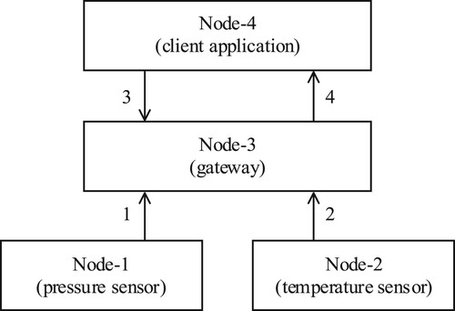
An example system shown in Figure 7 consists of four nodes. Node-1 and Node-2 are simple things that communicate with Node-3 over BLE. Node-3 and Node-4 communicate using the TCP/IP stack. Node-1 represents a pressure sensor that sends its readings once per hour to Node-3. Similarly, Node-2 represents a temperature sensor which also sends its readings once per hour to Node-3. Node-4 represents a client node that requests data from Node-3 about the readings from sensor nodes, Node-1 and Node-2.
In the presented scenario, the first message (1) is sent by Node-1, with its readings. Node-3 receives this message and stores it. Next, Node-2 sends its own readings (2). Such messages are sent repeatedly (with new readings), once per hour. Sometime later, Node-4 requests readings for a specific period of time (3) and then receives the response from Node-3 (4). The description of the previous messages follows.
Node-1 sends a DATA message (message 1 from Figure 7) with all the metaprotocol fields, as shown in . Since all the fields are present in this message, there is no need to use BLE capabilities, and hence BLE is not analyzed for this message. The purpose of Table 3 is to showcase the proposed message format in its most complete form.
Table A3. Elements of message 1.
When the message is created, the message identifier (0 × 48) is randomly generated, the source and destination identifiers are usually generated from Extended Unique Identifiers (EUIs, extracted from BLE addresses), the message length represents only the payload length and the CRC is calculated over the entire message. For simplicity, the source and destination identifiers in the example are set to simple values. In this example, the message payload is a string “pres=1034” (“pres” as in “pressure”), which is interpreted as a DATA message.
After receiving the message 1, Node-3 creates a table “t111111fffe111111” (character “t” extended by the source identifier) with the default column “t” (TIMESTAMP(4) WITHOUT TIME ZONE) and a column from the DATA message – column “pres” with the type determined by the provided value, i.e. NUMERIC(4, 0).
If this were not the first message from Node-1, such a table would have already existed on Node-3. If the table exists, but without the column “pres”, this column will be added when this message is received. If the column “pres” exists, but with a less precise type, it will be extended.
Therefore, the received message is expanded to {pres=1034,t=LOCALTIMESTAMP(4)}, and inserted into the table “t111111fffe111111”.
In this example message, all protocol fields are surely not needed, as most of them could be derived from the BLE fields, as shown further for the message 2.
Node-2 sends its reading using the QUICK simplest message type, which contains only one byte, no other message elements or even a header, just the payload. Since BLE is used, the packet containing this message consists of the fields listed in .
Table A4. BLE packet for message 2.
Since the message length (calculated from the BLE packet elements) is only one byte, Node-3 processes the message as the QUICK type and therefore generates other message elements by extracting information from the BLE packet, or calculating them, or using default values. In this example, the message header is deduced to zero (0×00), the message payload length to 0×01, the source identifier to the sensor's EUI-64 (0×222222fffe222222 expanded from AdvA), the destination identifier to the gateway's EUI-64 – since broadcast is implied. The CRC is computed over the 1-byte message (and still checked), and its first byte is further used ad-hoc as the message identifier. Then, the payload is expanded from AdvData to “d=20” (0×14=20) and, as with the message from Node-1, the table “t222222fffe222222” is created with only the columns “d” and “t” columns, and finally the row {20, LOCALTIMESTAMP(4)} is inserted.
In further examples and messages, the focus will be only on their payload. Other required fields are either provided in the message or generated from the packet, but without detailed explanation.
The next event from the described scenario involves Node-4, asking for sensor readings on 2022-01-01 from 10 h to 14 h. The message it sends to Node-3 is of type SELECT and it contains the following SQL-standard query in its payload:
SELECT ALL t1.pres AS pres, t2.d AS temp FROM t111111fffe111111 AS t1 INNER JOIN t222222fffe222222 AS t2 ON CAST(t1.t AS DATE) = CAST(t2.t AS DATE) AND EXTRACT(HOUR FROM t1.t) = EXTRACT(HOUR FROM t2.t) WHERE CAST(t1.t AS DATE) = DATE ‘2022-01-01’ AND EXTRACT(HOUR FROM t1.t) BETWEEN 10 AND 14 ORDER BY t1.t ASC; (311 bytes).
\xDE\x85t1.pres\x87pres,t2.d\x87temp\xACt\x11\x11\x11\xFF\xFE\x11\x11\x11\x87t1\xB3\xB7t\x22\x22\x22\xFF\xFE\x22\x22\x22\x87t2\xEFCAST(t1.t\x87\x9B)=CAST(t2.t\x87\x9B)\x84EXTRACT(\xB2\xACt1.t)=EXTRACT(\xB2\xACt2.t)\xFBCAST(t1.t\x87\x9A)=\x9A‘2022-01-01’\x84EXTRACT(\xB2\xAC t1.t)\x8C10\x8414\xD1\x8Ft1.t\x88 (164 bytes encoded).
pres,temp=1030,19;1031,20;1032,20;1031,21;1030,21
B. Example 2. Operation subscribe
In the second example, the same system as the previous one from Figure 7 is used, but with additional functionality: Node-4 requires notification when the temperature sensor sends a value greater than 20 °C. Therefore, Node-4 sends the following subscription request to Node-3 (message SELECT_SUBSCRIBE):
SELECT ALL t1.d FROM t222222fffe222222 AS t1 WHERE t1.d > 20 SUBSCRIBE 1;
Figure A2. Distributed IoT system example.
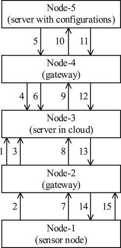
SQL triggers could be used in the subscription feature implementation (as in the prototype). Whenever some data is changed in any of the tables named in the subscription query, the query is to be executed again, and if there is a set (as in “set theory”) difference from the previous result, the difference is returned to the subscriber.
In this example, Node-4 requires Node-3 to execute the given query whenever data is received from the temperature sensor, i.e. here whenever data is inserted into the table t222222fffe222222. For example, if Node-2 sends a temperature of 23, Node-3 inserts a value of 23 into the device's table and then, on a trigger, runs the subscription query. If this produces some new result, it sends it to Node-4 in a DATA message (message d=23 or 0×17).
C. Example 3. Distributed system
The nodes for the next example are shown in Figure 8. The example simulates a hierarchical distributed system with Node-3 at the top and nodes Node-1 and Node-5 at the bottom of the hierarchy. Node-1 represents a sensor, Node-2 is an IoT gateway near the sensor location, while Node-3 is a remote server that serves as a default forwarding point for Node-2. Node-5 represents an IoT node at another remote location where the configuration for Node-1 (and possibly others) is defined. Node-5 is not directly reachable, but Node-4 serves as its IoT gateway. Node-4, similarly to Node-2, uses Node-3 as its default forwarding node.
In this example, it is assumed that a simpler underlying protocol is used between Node-1 and Node-2, and between Node-4 and Node-5 (e.g. BLE), while Node-3 is connected to Node-2 and Node-4 through some Internet protocol (e.g. TCP, UDP, HTTPS …).
Nodes higher in hierarchy might not know the statuses and addresses of lower nodes without the lower nodes explicitly announcing this to them. For this announcement (awareness), any message sent by the lower nodes is sufficient. However, if there is no information to convey, a simple HELLO message can be used, e.g. when such nodes are booted up.
In the scenario presented in this example, when the nodes are started, a HELLO message is sent in the following order: Node-2 to Node-3 (message 1 from Figure 8), Node-1 to Node-2 (2), Node-2 to Node-3 (3 – forwarded message 2), Node-4 to Node-3 (4), Node-5 to Node-4 (5), and Node-4 to Node-3 (6 – forwarded message 5).
It is also assumed that, in this scenario, Node-1 must periodically send its readings to Node-2. However, firstly Node-1 must retrieve the period defined in minutes from Node-5. Therefore, the next message (7) is sent by Node-1 to Node-2 (as its default gateway) but destined for Node-5. Node-2 forwards this message to its default gateway Node-3 (8). Node-3 determines (in its data structures) that Node-5 is reachable through Node-4 and forwards the message to it (9), and finally Node-4 forwards the message to Node-5 (10). The message that Node-1 had sent is a SELECT message:
SELECT ALL period FROM configs WHERE node_id=X’111111FFFE111111’;
period=20
Node-1 can now start sending sensor readings every 20 minutes (message 15 from Figure 8; Node-1 knows the time unit). Node-1 can use a DATA message (e.g. “reading=123”) or, if a result can be fitted into a byte, a QUICK message (e.g. 0×7B, meaning “d=123”).
D. Example 4. Security and privacy
The last example demonstrates the use of security of the underlying transfer protocol where it is available, but also the use of additional security mechanisms used by the proposed metaprotocol when the underlying protocol is not sufficient.
For this purpose, the same nodes as in Example 3 from Figure 8 are used. In this example, secure communication is requested between Node-1 and Node-5, not allowing other parties involved in the message transfer to view the message content (except for the nodes enabling security). E.g. since Node-2 communicates with Node-3 over TCP/IP, there are usually many nodes (routers) between them transmitting their packets. None of them should be able to see the contents of the message.
If all underlying transfer protocols (between Node-1 and Node-2, between Node-2 and Node-3, etc.) support sufficiently secure mechanisms, then the use of these mechanisms is required by the C flag in the message header. Otherwise, the security mechanisms of the proposed metaprotocol must be used. The security mechanisms are demonstrated using two subexamples.
In these subexamples it is assumed that Node-1 from Figure 8 must send a message (e.g. with payload “data=56”) securely to Node-5. Node-1 and/or Node-5 may or may not have cryptographic capabilities.
In the first example, both nodes, Node-1 and Node-5, can secure messages through the metaprotocol, as shown in the subsection III.D. In this example, only Node-1 and Node-5 can see the message payload in its original (decrypted) form. Nodes Node-2, Node-3 and Node-4 should use a secure transport mechanism (e.g. TLS, DTLS) when transporting the message because flags C and/or A are set in the message header, but they cannot decrypt/verify the payload.
In the second example, Node-1 cannot use security mechanisms (e.g. because it is a very resource-constrained node without the required capabilities). In this case it is up to Node-2 to know this, and (as a trusted node/gateway) to provide the requested security. Node-2 must have explicit rules that are triggered when a message arrives from Node-1 and the flags C/A are set. There must also be complementary rules when a message arrives for Node-1. Node-2 acts on behalf of Node-1 and therefore must have its credentials (both private and public key). Node-5 can provide security itself in this example. The presented example assumes that in the local network the security is achieved by other means (e.g. by physical inaccessibility or by lower-layer protocols) and that only the transmission over the public networks is untrustworthy.