
 ?Mathematical formulae have been encoded as MathML and are displayed in this HTML version using MathJax in order to improve their display. Uncheck the box to turn MathJax off. This feature requires Javascript. Click on a formula to zoom.
ABSTRACT
In a piloted jet flame, the pilot flame has an effect of stabilizing the main flame. Detailed mechanisms of pilot flame/main flame interaction are however not well studied. It is expected that the pilot flame affects the main flame through the following mechanisms: (a) the pilot flame provides the heat and radicals to the reaction zone of the main flame, (b) the pilot flame prevents the cold ambient air from being entrained into the main flame, and (c) the pilot flame modifies the stretch rate of the main flame. In this paper, detailed numerical simulations of piloted laminar methane/air jet flames are carried out to elucidate the effect of pilot flame on the structure and burning velocity of the main jet flame. One-dimensional (1D) freely propagating flame is also simulated to investigate the effect of hot gas mixing with the unburned fuel/air mixture, and 1D counter-flow flame is simulated to study the diffusion of the hot gas from the pilot flame to the reaction zone of the main flame and the effect of flame stretch. The results showed that heat transfer from the pilot flame to the main flame has a more significant effect on the structures and propagation of the main flame than the mass transfer from the pilot flame to the main flame. The heat and mass transfer from the pilot flame affects the local equivalence ratio and temperature of the unburned mixture, which gives rise to a significant enhancement of burning velocity. When the hot gas from the pilot flame is at sufficiently high temperatures, an ultra-lean fuel/air mixture can burn at equivalence ratio below the flammability limit. The reaction rate and burning velocity of ultra fuel-lean flames are enhanced by the strain rate, whereas for a main flame with the equivalence ratio closer to that of pilot flame, the reactivity and burning velocity of the main flame decrease with increasing strain rate.
Introduction
Pilot flames are frequently used to stabilize combustion process under challenging conditions, for example, in gas turbine engines running at part load under lean premixed conditions (Moëll, Lörstad, Bai Citation2016, Citation2018), or during the startup ignition period of engine operation. In recent experiments of high speed jet premixed flames running at high Karlovitz numbers, large pilot flames have been used to enable the stabilization of the flames to the burners (Dunn, Masri, Bilger Citation2007; Dunn et al. Citation2009; Li et al. Citation2010; Skiba et al. Citation2016; Wabel, Skiba, Driscoll Citation2017; Zhou et al. Citation2015a). In some studies, the power generated by the pilot flames are much greater than the power generated by the main flame (Li et al. Citation2010; Zhou et al. Citation2015a, Citation2017b). A question is, how does pilot flame affect the main flame?
It is expected that the pilot flame can affect the main flame through affecting the turbulent flow (hence the wrinkling and stretching the flame), and through shielding the main flame from cold ambient air entrainment. Dunn et al. (Dunn, Masri, Bilger Citation2007) investigated experimentally a lean premixed methane/air jet flame supported by a stoichiometric pilot methane/air flame based on the Sydney University premixed piloted jet burner (PPJB). They found that the pilot flame can delay the turbulence generation, leading to the peak turbulence intensity shifting downstream. Furthermore, it was also reported that the central jet was significantly influenced by the pilot flame at relatively lower speed, e.g., at 50m/s, and the impact of pilot decreased gradually with increasing jet velocity as the hot products from the pilot flame are mixed and cooled by the cold ambient coflow at high jet velocity conditions (Dunn et al. Citation2009). Li et al. (Li et al. Citation2010; Zhou et al. Citation2015a) reported the shielding effect of pilot flame in the Lund University piloted jet (LUPJ) flames. The central jet has a diameter of 2.2 mm whereas the pilot flame burner has a diameter of 22 mm. It was shown that when the jet velocity is at 150 m/s, the upper part of the flame is quenched due to the cold air entrainment to the flame. By increasing the diameter of pilot flame burner from 22 mm to 61 mm, the central jet flame can be stabilized at much higher jet velocity, e.g., at 330 m/s, without observing flame quenching. Driscoll and colleges (Skiba et al. Citation2018, Citation2016; Wabel, Skiba, Driscoll Citation2017) conducted a series experiments on the Michigan Hi-Pilot (High Reynolds number-piloted flame) burner. They observed that a smaller pilot flame could not shield the flame from ambient air; the cold air entrainment could significantly affect the reaction layer downstream (Skiba et al. Citation2016).
Pilot flames with equivalence ratio close to unity can support the main flame with not only hot gas but also radicals and fuels that are not completely oxidized, e.g., carbon monoxide and hydrogen. These fuels and radicals can help the combustion of the fuel/air mixture of the main flame when it is at ultra fuel-lean conditions, e.g. (Zhou et al. Citation2015a, Citation2017a), a condition that is outside the lean flammability limit. This situation is similar to the double-chamber gas engines where a fuel-rich combustion in a pre-chamber is used to support the fuel-lean combustion in the main combustion chamber (Qin et al. Citation2018).
High Reynolds number jet flames without pilot flame stabilization are frequently lifted off the burner rim (or even blown out when the jet speed is high enough). This is due to the high local flame stretch rate and heat loss in the proximity of the burner. Wang et al. (Wang et al. Citation2017b, Citation2017a) conducted a direct numerical simulation (DNS) on the LUPJ flame with ,
. It was shown that the gradient of temperature and composition existing between the pilot and the main flame affected the inner flame structure considerably in the near field. They reported that the local displacement speed of the flame was negative near the burner exit – the reaction front was propagating to the hot combustion products generated in the pilot flame, rather than conventional flame propagation to the unburned mixture.
In summary, despite the wide use of pilot flames in academic fundamental studies and industrial applications, detailed study on the interaction between pilot flames and main flames is rather rare. One may envisage that the following effects of pilot flames on the main flame may be important: (a) supporting the main flame with the heat, incompletely oxidized fuels, and radicals (back-support effect), (b) shielding the main flame from the cold ambient air entrainment, (c) modifying the stretch rate of the main flame. Furthermore, the pilot flame usually has a mixture close to stoichiometric, which may improve the local equivalence ratio of the main jet flame when the main flame is running at ultra fuel-lean conditions. By doing so the main flame is strengthened.
This paper is aimed at elucidating the mechanisms of pilot flame and main flame interaction. The LUPJ flame is simulated using detailed chemical kinetics and transport properties under laminar flame conditions with different main flame equivalence ratios. The numerical simulations are supported by simultaneous multiple species planar laser-induced fluorescence (PLIF) experiments. To investigate the effect of back-support and flame stretch, detailed numerical simulations of one dimensional (1D) counter-flow flames are considered. To scrutinize the effect of mixing the hot combustion products to the unburned fuel/air mixtures of the main flame, 1D freely propagating flames are simulated with different mixing ratios.
Experimental rig and numerical setup
Three cases of piloted laminar jet flame were studied experimentally with the simultaneous multi-species laser diagnostic method for the LUPJ flame burner configuration (Wang et al. Citation2019; Zhou et al. Citation2015b). The experimental cases are considered in the present numerical simulations. lists the case setup and operating conditions. The burner is made up of a central jet of the diameter of 1.5 mm and a coflow pilot flame burner of the diameter of 61 mm. In the central jet, CHair mixtures at varying equivalence ratios are injected with a constant speed
into the surrounding hot gas from the pilot flame. The pilot flame has a constant equivalence ratio of
with a CH
air mixture. The fuel/air mixtures in both the pilot burner and the main jet are supplied with the unburned gas temperature of
and at atmospheric pressure. The fuel/air mixture from the pilot burner is supplied at a speed of
. The boundary condition of the pilot flame burner is set at the downstream of the pilot flame, i.e., at the exit of the pilot burner the gas mixture is assumed to be that of the combustion product from the methane/air flame with
,
and atmospheric pressure. The hot gas velocity is
, and the hot gas temperature is
. This temperature is taken from the experiments, which is lower than the adiabatic flame temperature of the mixture due to the heat loss to the burner. The mass fractions of species in the hot gas are obtained from the solution of 1D freely propagating flame for the mixture condition of the pilot flame. shows the mass fractions of the major species in the hot gas.
Table 1. Case setup in the numerical simulations. ,
for all cases
A fourth case, LU11-0.7C, is simulated to investigate the effect of on the main flame. The boundary conditions at the pilot burner are set in the same way as that for the three experimental flame cases, cf. . The temperature of the pilot flame is assumed to be
as well. This temperature is about the adiabatic flame temperature of the pilot flame. Since case LU11-0.7C has the same
as that in case LU11-0.7, one can distinguish the effect of pilot gas composition from the effect of the pilot gas temperature.
The 2D axisymmetric computational domain is based on the exact burner geometry in experiments, which extends 50 (
) in the axial direction downstream the burner exit plane, and 50
in the radial direction as well. The central fuel jet is made up of a straight pipe,
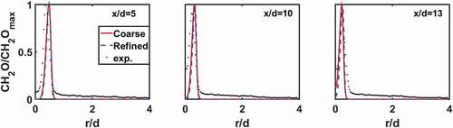
in length, which is simulated to achieve a fully developed laminar profile at the exit of the jet. Grid-sensitivity study was performed based on two sets of grid, with, respectively, 0.5 million and 2 million mesh cells, corresponding to 5 and 10 cells in the reaction zone to resolve the laminar flame. As will be shown later the two grids yield identical results.
The open source code OpenFOAM (Jasak Citation2009) was adopted to simulate the jet flame with a 2D axisymmetric configuration. A second-order Gauss linear scheme is utilized for the spatial discretization and the second-order backward Euler scheme is utilized for the temporal integration. The pressure implicit with splitting of operator (PISO) algorithm is used for the pressure-velocity coupling.
The 1D flame simulation was carried out using ANSYS CHEMKIN. Both 1D freely propagating flame and 1D counter-flow flame configurations were considered to study the pilot flame mixing effect and the strain rate effect. A chemical kinetic mechanism, known as the DRM22 mechanism (Kazakov and Frenklach Citation1994), was employed in all the calculations. The mechanism is a relatively detailed one consisting of 22 species and 104 reactions.
Structure of piloted laminar jet flames
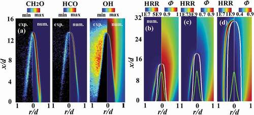
shows the spatial distribution of CHO, HCO and OH from the simulations and experiments for case LU11-1.0. Previous studies have shown that CH
O can be used as a marker of the preheat zone of the flame (Li et al. Citation2010), and HCO as a marker of the reaction zone (Zhou et al. Citation2015a), whereas OH radicals exist in both the reaction zone and in the hot gas. As seen from the PLIF signals, both CH
O and HCO are in rather thin layers in the present flame, while OH are found in wider regions. The numerical simulation replicates very well the spatial distributions of all these species observed in the experiments. It is worth mentioning that in the proximity of the burner rim rather weak PLIF signal intensity is detected in the experiments for all three species, which is predicted qualitatively well in the simulations. At the upper half of the flame, OH is shown to have its highest mass fraction in the numerical simulations, which is consistent with the PLIF experiments. The OH PLIF signal at the flame tip is somewhat weaker than the peak PLIF signal intensity, owing to the weaker laser intensity near the boundary of laser sheet. This result is consistent with an earlier work (Hu et al. Citation2018) where it was shown that near the burner rim the stretch rate is positive (under which the flame is weakened), whereas at the flame tip the stretch rate is negative, which strengthens the flame with a higher concentration of OH fields.
Figure 1. (a) Spatial distribution of CHO, HCO, and OH PLIF signal intensity and mass fractions of these species from numerical simulation for case LU11-1.0, and spatial distributions of heat release rate (HRR) and equivalence ratio (
) from numerical simulations for cases LU11-1.0 (b), LU11-0.7 (c), and LU11-0.4 (d). The white line represents the iso-line of
in (b), 0.72 in (c), and 0.55 in (d), respectively, while the green line represents the mixing ratio
, nearly unaffected by the pilot flame. The numerical results are based on the fine grid.
The mass fraction of CHO for the case LU11-1.0 from numerical simulations using different grids are compared with the experimental results, cf. , for three axial positions. The results from the two sets of grid are almost identical; thus, in the following discussion the fine grid with 2 million cells will be used. The numerical results agree well with the experimental data in the region with the high concentration of CH
O; however, in the low concentration regions, there is certain discrepancy. In the experiments, certain low level of CH
O is shown outside the flame region, which is likely due to the background noise. This can be confirmed in where CH
O PLIF signal outside the narrow flame region is uniformly weak. For the same reason, certain low level of CH
O is observed along the centerline of the flame, whereas in the numerical simulations CH
O on the centerline is predicted only at the flame tip, i.e.,
Figure 2. CHO mass fraction from numerical simulations and CH
O LIF signal intensity from measurements along radial direction at three different axial positions for the LU11-1.0 case. The quantities are normalized by their corresponding peak values.
shows the spatial distribution of heat release rate (HRR) and equivalence ratio () from the simulations for the three experimental flame cases. The equivalence ratio is defined as
, where
is the mass fraction of element
, and
is the atomic weight of element
, where
C, H, and O. C and H are not only from the center jet stream but also from the pilot flame stream. The white line is an isoline of
that is chosen to cross over the flame tip (the HRR zone on the centerline of the flame). It is clear that the equivalence ratio in the unburned region (enclosed by the HRR layer) is no longer equal to that on the exit of the center jet (
). Unlike idealized-premixed flames, the equivalence ratio across the piloted-premixed flames varies due to the diffusion between the jet flow stream and the coflow stream from the pilot flame. It is expected that without the pilot flame the ambient air entrainment will affect the equivalence ratio in the unburned mixture as well. This effect is referred here to as the pilot mixing effect. Since the main species in the pilot flow stream are N
, CO
and H
O, cf. , a pilot mixing ratio can be defined as
where is the mass fraction of N
in the local mixture, and subscripts jet and pilot denote the center jet stream and the pilot flow stream, respectively. The green line is an isoline of
, corresponding to a state that is nearly unaffected by the pilot. For the cases studied, the reaction zones denoted by HRR have values much larger than 0.001 (away from green lines), indicating that the main flame is influenced by the pilot somehow. In addition, the more differences of pilot equivalence ratio from that of the main flame, the more significant the dilution effects.
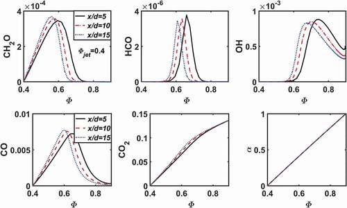
shows the distribution of mass fractions of key species and the mixing ratio at three flame heights along the radial direction (displayed as a function of , since
increases monotonically in the radial direction) for the case LU11-0.4. It is clear that the mixing ratio (
) is nearly a linear function of
. Since the mass fraction of HCO may be used to denote the reaction zone, it appears that the reaction zone is around
, where the mixing ratio is around
, i.e., about 50% of the mass in the reaction zone is from the pilot flame. As the axial distance to the burner increases, from
to 15, the reaction zone is shifting to lower
; the peak values of HCO and OH decrease, while the peak values of CH
O and CO increase.
Figure 3. Mass fractions of key species and the mixing ratio as a function of equivalence ratio at three axial positions from numerical simulation for the case LU11-0.4.
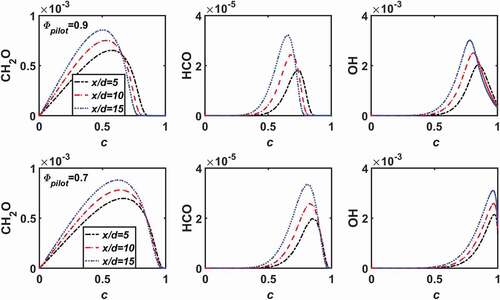
The effect of pilot gas mixing on the structure of the flame is further explored by comparing the cases LU11-0.7 and LU11-0.7C. The two cases have the same but different
. Since the case LU11-0.7C has the same equivalence ratio in the main jet and the pilot, the mixing ratio defined earlier is not applicable. Instead, here we display the results as a function of a reaction progress variable, defined as (Wang et al. Citation2017b),
From , it is shown that with the reaction zone (indicated by HCO) is around
, whereas for
the reaction zone is shifted to lower
. The peak mass fractions of CH
O, HCO, and OH increase along flame height; however, their values are not strongly affected by the increase of
.
Figure 4. Mass fractions of CHO, HCO, and OH as a function of reaction progress variable (
) at three different flame heights for the cases with
and two pilot flame conditions,
(top) and
(bottom).
The global consumption speed, , is calculated using the flame-cone-angle method, which has a higher accuracy than the flame-area method (Hu et al. Citation2018). lists the values of
for different cases from the numerical simulations. Comparing the cases LU11-0.7 and LU11-0.7C, it is seen that
is not sensitive to the value of
, which is consistent with the species distribution in .
Effect of pilot mixing ratio on the structure and propagation of premixed flames
In order to quantify the mixing effects of the pilot gas, 1D freely propagating laminar flames are simulated under different pilot mixing ratios . By assuming that the Lewis numbers for all species are the same and the heat capacity is a constant, the inflow condition is presumed as follows, by making use of the definition of
in EquationEquation (3)
(3)
(3) ,
Here, subscript jet denotes the unburned fuel/air mixture before mixing with the gas from the pilot flame. The species of the hot gas from the pilot flame is given in . H, O and OH radicals in the hot gas are assumed to be absent due to recombination reactions in the mixing process. The hot gas temperature is assumed to be , the same as those used in the piloted jet flame studies discussed earlier, cf. .
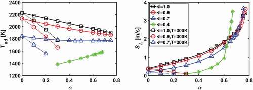
shows the adiabatic flame temperature and the laminar burning velocity (
) for different mixing ratios and
. It is shown that with an increasing mixing ratio,
approaches to the pilot flame temperature. For
, 0.9, and 0.7, as their adiabatic flame temperatures are higher than 1800
which is the temperature of the pilot gas,
decreases with increasing
. Despite the monotonic decrease of
with
,
increases monotonically with
. When
the increase of
is accelerated, indicating a possible change of combustion mode from laminar flame propagation to ignition-assisted flame propagation. This will be discussed further below. For the case with
, the mixture can not be ignited without sufficient mixing with the pilot flame; when
the mixture can be ignited and
increases rapidly with increasing
. The laminar flame speed increases also very rapidly with
when
.
Figure 5. Adiabatic flame temperature and laminar flame speed under different mixing ratio and unburned fuel/air mixture equivalence ratio
. The equivalence ratio of the pilot flame is kept constant as
.
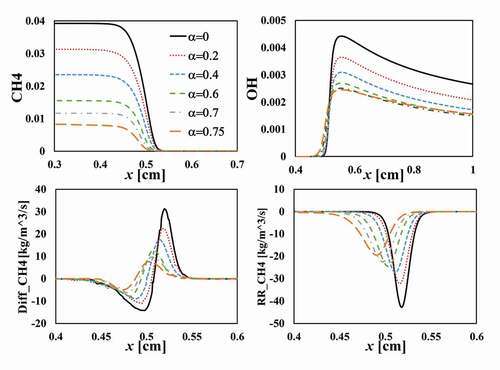
To understand the mechanisms of pilot flame mixing on the acceleration of the laminar flame speed, displays the spatial distribution of mass fractions of CH and OH across the flame, along with the diffusion rate and reaction rate of CH
. With increasing
, the unburned fuel/air mixture is diluted with hot gas from the pilot flame, leading to a decreasing mass fraction of CH
in the unburned mixture, which results in a decreasing diffusion rate of CH
to the reaction zone. The peak of OH mass fraction decreases with increasing
due to the lower amount of fuel. Since the adiabatic flame temperature decreases with increasing
, cf. , a decreasing radical concentration and flame temperature gives rise to a decreasing reaction rate, . The laminar burning velocity depends on the gradient of the fuel mass fraction (
), the diffusion rate (
) and the reaction rate (
) of the fuel, and the density of the unburned mixture (
), viz.,
From EquationEquation (4)(4)
(4) and it appears that
,
, and
, whereas
. It appears that main reason that
increases with increasing
is that the density of the unburned mixture decrease strongly with increasing
since the temperature ratio is very large,
. The above scaling shows a nearly linear increase of laminar burning velocity with
, which is consistent with results shown in for moderately large
, e.g.,
. For higher
, the temperature in the unburned mixture becomes so high that the mixture is undergoing self-ignition, and the propagation of the reaction zone is no longer a diffusion-reaction controlled flame propagation, but rather an ignition-assisted flame propagation, which can give rise to very high propagation speed. Specifically, the reaction rate becomes more significant in the “preheat” region (i.e.
), whereas the diffusion rate in the region remains low. This is clearly evidenced in , where
becomes very high and the numerical simulation using Chemkin for the 1D flame configuration becomes difficult to converge as
.
Figure 6. Axial distribution of mass fractions of CH and OH radicals, diffusion and reaction rate of CH
under different mixing ratio
with
and
.
The thermal effect of the pilot flame mixing is further verified in numerical simulations of three “cold” pilot gas cases, in which the hot gas from the pilot flame is first cooled to room temperature (300 K) and then mixes with the unburned fuel/air mixture. The pilot flame gas composition is kept the same as the hot gas from the pilot flame (with radicals removed). The results are shown in , labeled by ““. The case with
is not shown since it is un-flammable. As shown in the three flame cases with the temperature of unburned mixture
is flammable only for very small
, i.e.
. The adiabatic flame temperature and
decrease with increasing
.
Effect of strain rate on the flame structures
To take the strain rate effects into consideration, 1D counter-flow flames are simulated with a fresh fuel/air mixture stream (modeling the center fuel jet stream) counter-flowing toward a hot gas stream (modeling the pilot flame stream). lists the four counter-flow flame cases (CF-0.4 to CF-0.7C). The jet stream and the pilot gas stream conditions given in are selected to be the boundary conditions for the counter-flow flame cases, to allow the results comparable to the jet flame cases studied earlier.
Table 2. Case setup for the 1D counter-flow flames and the laminar flame fuel consumption speed [
] at varying strain rates
shows the temperature and the mass fraction of HCO along the axial distance for different
and strain rates. For the case of
and
, , it is shown that the mass fraction of HCO increases with increasing strain rate. The temperature in the reaction zone is lower than that in the pilot flame stream; thus, an increasing strain rate enhances the temperature gradient and the heat transfer from the pilot flame stream to the reaction zone (which is indicated by HCO). The mass fraction of OH radicals increases with the increasing strain rate as well, . It appears that an increasing of the strain rates pushes the reaction zone closer to the pilot flame stream that provides the temperature and radicals (e.g. OH) for the combustion of the ultra-lean fuel/air mixture from the fuel jet stream. As shown in , the fuel consumption speed (
) for this ultra-lean case increases with the increasing strain rate, where
is defined as:
where subscript F denotes the fuel. is equivalent to
in 1D freely propagating flames. The increase of the concentration OH radicals enhances the reaction rates, this being the reason of increased fuel consumption speed.
Figure 7. Spatial distribution of temperature and mass fraction of HCO radicals across the flame under different strain rates and equivalence ratios.
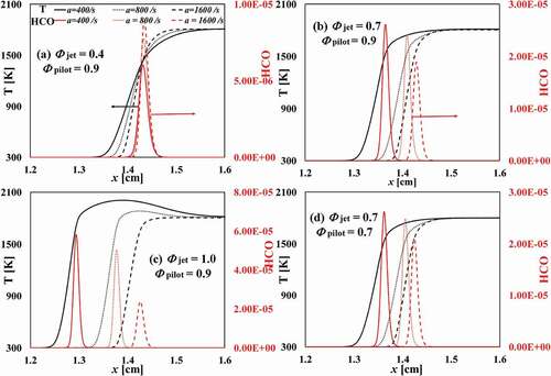
Figure 8. Spatial distribution of mass fraction of OH radicals across the flame under different strain rates and equivalence ratios.
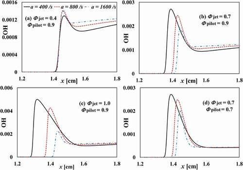
For the higher cases, the mass fractions of HCO and OH decreases with increasing strain rate, the case CF-1.0 being the most sensitive case to the strain rate. The reason is that for the CF-1.0 case, the flame temperature is higher than the hot gas temperature from the pilot flame stream; thus, increasing the strain rate leads to an increasing transfer (thus loss) of heat and radicals to the pilot flame stream, which results in a decrease of the reactivity. This gives rise to a decrease of the fuel consumption speed, cf. . For the CF-0.7 case and the CF-0.7C case, the adiabatic flame temperature is nearly the same as that of the hot gas temperature from the pilot flame stream. Thus, the heat loss to the pilot flame stream is negligible. The effect of strain on the flame is to enhance the heat and mass transfer from the flame to the unburned mixture, which suppresses the reaction rate in the reaction zone as indicated by the decreasing
, , this eventually leading to flame extinction.
Case CF-0.7C differs from case CF-0.7 in the pilot gas composition. In the former case the concentrations of CO and H
O are lower than those in the latter case, which gives a slightly higher flame temperature due to a lower heat capacity of the mixture. This leads to a higher reactivity and a higher
in the CF-0.7C case at the corresponding given strain rate.
Conclusion
Numerical simulations of piloted laminar premixed methane/air jet flames were carried out to investigate the effects of pilot flame on the structure and burning velocity of the main flames. The pilot flame was shown to have a significant effect on the main flame. The pilot flame affects the main flame through mixing the hot gas to the reaction zone of the main flame and by preventing the cold ambient air entrainment into the main flame. The main findings are summarized as follows:
(i) The reaction zone of the piloted jet flame is in the mixing layer of the main jet and the hot coflow from the pilot flame. The equivalence ratio in the reaction zone can be significantly higher than that in the fuel/air mixture of the main flame, especially for the main flame that has a much lower equivalence ratio than that of the pilot flame. This explains the sustained ultra fuel-lean main flame (with an equivalence ratio of 0.4, which is below the lean flammability limit) by the pilot flame with an equivalence ratio of 0.9.
(ii) The burning velocity of the main flame is insensitive to the hot gas composition from the pilot flame, indicating that the heat transfer from the pilot flame to the main flame has a more significant impact on the main flame than the transfer of the radicals and combustion intermediates (such as CO and H) from the pilot flame to the main flame. For a given pilot gas temperature of
, when the pilot flame equivalence ratio is varied from 0.9 to 0.7, the mass fractions of OH and O radicals in the hot gas from the pilot flame are decreased 4–5 folds, and the mass fractions of CO and H
are decreased about 20 times. The global fuel consumption speed of the main flame (with an equivalence ratio of 0.7) remains however nearly constant, with a minor variation from
to
.
(iii) Detailed numerical simulations were carried out under one-dimensional planar unstretched flame configuration for conditions relevant to that of the piloted jet flames. It was found that mixing between the hot gas and the fuel/air mixture of the main flame can significantly increase the burning velocity, which is due to the significant decrease in the mixture density and the gradient of fuel mass fraction, while not due to the increased reaction rate or the diffusion rate. In fact, the chemical reaction rate and the diffusion rate are lower in the fuel/air/hot gas mixture than that of the pure fuel/air mixture.
(iv) The stretch rate affects the flame in different ways. When the main flame is ultra-lean, e.g., below the flammability limit, the reactivity and burning velocity of the main flame are both enhanced by the increasing strain rate. The increasing strain rate enhances the mixing of the hot gas from the pilot flame to the main flame. When the main flame and the pilot flame have a similar equivalence ratio, the reactivity and burning velocity of the main flame decrease with the strain rate. The sensitivity to the strain rate is higher when the flame temperature is higher than the pilot flame temperature.
Additional information
Funding
References
- Dunn, M., A. Masri, R. Bilger, R. Barlow, and G.-H. Wang. 2009. The compositional structure of highly turbulent piloted premixed flames issuing into a hot coflow. Proc. Combust. Inst. 32 (2):1779–86. doi:https://doi.org/10.1016/j.proci.2008.08.007.
- Dunn, M. J., A. R. Masri, and R. W. Bilger. 2007. A new piloted premixed jet burner to study strong finite-rate chemistry effects. Combust. Flame 151 (1–2):46–60. doi:https://doi.org/10.1016/j.combustflame.2007.05.010.
- Hu, S., J. Gao, C. Gong, Y. Zhou, X. Bai, Z. Li, and M. Aldén. 2018. Assessment of uncertainties of laminar flame speed of premixed flames as determined using a Bunsen burner at varying pressures. Appl. Energy 227:149–58. doi:https://doi.org/10.1016/j.apenergy.2017.09.083.
- Jasak, H. 2009. OpenFOAM: Open source CFD in research and industry. Int. J. Nav. Archit. Ocean Eng. 1 (2):89–94.
- Kazakov, A., and M. Frenklach. 1994. Reduced reaction sets based on GRI-Mech 1.2. Berkeley: University of California at Berkeley. http://www. me. berkeley. edu/drm
- Li, Z., B. Li, Z. Sun, X.-S. Bai, and M. Aldén. 2010. Turbulence and combustion interaction: High resolution local flame front structure visualization using simultaneous single-shot PLIF imaging of CH, OH, and CH2O in a piloted premixed jet flame. Combust. Flame 157 (6):1087–96. doi:https://doi.org/10.1016/j.combustflame.2010.02.017.
- Moëll, D., D. Lörstad, and X.-S. Bai. 2016. Numerical investigation of methane/hydrogen/air partially premixed flames in the SGT-800 burner fitted to a combustion rig. Flow Turbul. Combust. 96 (4):987–1003. doi:https://doi.org/10.1007/s10494-016-9726-5.
- Moëll, D., D. Lörstad, and X.-S. Bai. 2018. LES of hydrogen enriched methane/air combustion in the SGT-800 burner at real engine conditions. ASME Turbo Expo 2018: Turbomachinery Technical Conference and Exposition, American Society of Mechanical Engineers, Oslo, Norway, V04BT04A023–V04BT04A023.
- Qin, F., A. Shah, Z.-W. Huang, L.-N. Peng, P. Tunestal, and X.-S. Bai. 2018. Detailed numerical simulation of transient mixing and combustion of premixed methane/air mixtures in a pre-chamber/main-chamber system relevant to internal combustion engines. Combust. Flame 188:357–66. doi:https://doi.org/10.1016/j.combustflame.2017.10.006.
- Skiba, A. W., T. M. Wabel, C. D. Carter, S. D. Hammack, J. E. Temme, and J. F. Driscoll. 2018. Premixed flames subjected to extreme levels of turbulence part I: Flame structure and a new measured regime diagram. Combust. Flame 189:407–32. doi:https://doi.org/10.1016/j.combustflame.2017.08.016.
- Skiba, A. W., T. M. Wabel, J. Temme, and J. F. Driscoll. 2016. Experimental assessment of premixed flames subjected to extreme turbulence. 54th AIAA Aerospace Sciences Meeting, San Diego, California, 1454.
- Wabel, T. M., A. W. Skiba, and J. F. Driscoll. 2017. Turbulent burning velocity measurements: Extended to extreme levels of turbulence. Proc. Combust. Inst. 36 (2):1801–08. doi:https://doi.org/10.1016/j.proci.2016.08.013.
- Wang, H., E. R. Hawkes, and J. H. Chen. 2017a. A direct numerical simulation study of flame structure and stabilization of an experimental high Ka CH4/air premixed jet flame. Combust. Flame 180:110–23. doi:https://doi.org/10.1016/j.combustflame.2017.02.022.
- Wang, H., E. R. Hawkes, J. H. Chen, B. Zhou, Z. Li, and M. Aldén. 2017b. Direct numerical simulations of a high Karlovitz number laboratory premixed jet flame – An analysis of flame stretch and flame thickening. J. Fluid Mech. 815:511–36. doi:https://doi.org/10.1017/jfm.2017.53.
- Wang, Z., B. Zhou, S. Yu, C. Brackmann, Z. Li, M. Richter, M. Aldén, and X.-S. Bai. 2019. Structure and burning velocity of turbulent premixed methane/air jet flames in thin-reaction zone and distributed reaction zone regimes. Proc. Combust. Inst. 37 (2):2537–44. doi:https://doi.org/10.1016/j.proci.2018.09.023.
- Zhou, B., C. Brackmann, Q. Li, Z. Wang, P. Petersson, Z. Li, M. Aldén, and X.-S. Bai. 2015a. Distributed reactions in highly turbulent premixed methane/air flames: Part I. Flame structure characterization. Combust. Flame 162 (7):2937–53. doi:https://doi.org/10.1016/j.combustflame.2014.12.021.
- Zhou, B., C. Brackmann, Z. Li, M. Aldén, and X.-S. Bai. 2015b. Simultaneous multi-species and temperature visualization of premixed flames in the distributed reaction zone regime. Proc. Combust. Inst. 35 (2):1409–16. doi:https://doi.org/10.1016/j.proci.2014.06.107.
- Zhou, B., C. Brackmann, Z. Wang, Z. Li, M. Richter, M. Aldén, and X.-S. Bai. 2017a. Thin reaction zone and distributed reaction zone regimes in turbulent premixed methane/air flames: Scalar distributions and correlations. Combust. Flame 175:220–36. doi:https://doi.org/10.1016/j.combustflame.2016.06.016.
- Zhou, B., M. Costa, Z. Li, M. Aldén, and X.-S. Bai. 2017b. Characterization of the reaction zone structures in a laboratory combustor using optical diagnostics: From flame to flameless combustion. Proc. Combust. Inst. 36 (3):4305–12. doi:https://doi.org/10.1016/j.proci.2016.06.182.