
 ?Mathematical formulae have been encoded as MathML and are displayed in this HTML version using MathJax in order to improve their display. Uncheck the box to turn MathJax off. This feature requires Javascript. Click on a formula to zoom.
Abstract
Since they were introduced in the 1990s, Lie group integrators have become a method of choice in many application areas. These include multibody dynamics, shape analysis, data science, image registration and biophysical simulations. Two important classes of intrinsic Lie group integrators are the Runge–Kutta–Munthe–Kaas methods and the commutator free Lie group integrators. We give a short introduction to these classes of methods. The Hamiltonian framework is attractive for many mechanical problems, and in particular we shall consider Lie group integrators for problems on cotangent bundles of Lie groups where a number of different formulations are possible. There is a natural symplectic structure on such manifolds and through variational principles one may derive symplectic Lie group integrators. We also consider the practical aspects of the implementation of Lie group integrators, such as adaptive time stepping. The theory is illustrated by applying the methods to two nontrivial applications in mechanics. One is the N-fold spherical pendulum where we introduce the restriction of the adjoint action of the group to
, the tangent bundle of the two-dimensional sphere. Finally, we show how Lie group integrators can be applied to model the controlled path of a payload being transported by two rotors. This problem is modelled on
and put in a format where Lie group integrators can be applied.
1. Introduction
In many physical problems, including multi-body dynamics, the configuration space is not a linear space, but rather consists of a collection of rotations and translations. A simple example is the free rigid body whose configuration space consists of rotations in 3D. A more advanced example is the simplified model of the human body, where the skeleton at a given time is described as a system of interacting rods and joints. Mathematically, the structure of such problems is usually best described as a manifold. Since manifolds by definition can be equipped with local coordinates, one can always describe and simulate such systems locally as if they were linear spaces. There are of course many choices of local coordinates, for rotations some famous ones are: Euler angles, the Tait–Bryan angles commonly used in aerospace applications, the unit length quaternions and the exponentiated skew-symmetric -matrices. Lie group integrators represent a somewhat different strategy. Rather than specifying a choice of local coordinates from the outset, in this approach the model and the numerical integrator are expressed entirely in terms of a Lie group and its action on the phase space. This often leads to a more abstract and simpler formulation of the mechanical system and of the numerical schemes, deferring further details to the implementation phase.
In the literature, one can find many different types and formats of Lie group integrators. Some of these are completely general and intrinsic, meaning that they only make use of inherent properties of Lie groups and manifolds as was suggested in [Citation6,Citation11,Citation41]. But many numerical methods have been suggested that add structure or utilize properties which are specific to a particular Lie group or manifold. Notable examples of this are the methods based on canonical coordinates of the second kind [Citation45], and the methods based on the Cayley transformation [Citation13,Citation32], applicable, e.g. to the rotation groups and Euclidean groups. In some applications, e.g. in multi-body systems, it may be useful to formulate the problem as a mix between Lie groups and kinematic constraints, introducing for instance Lagrange multipliers. Sometimes this may lead to more practical implementations where a basic general setup involving Lie groups can be further equipped with different choices of constraints depending on the particular application. Such constrained formulations are outside the scope of the present paper. It should also be noted that the Lie group integrators devised here do not make any a-priori assumptions about how the manifold is represented.
The applications of Lie group integrators for mechanical problems also have a long history, two of the early important contributions were the Newmark methods of Simo and Vu–Quoc [Citation50] and the symplectic and energy-momentum methods by Lewis and Simo [Citation32]. Mechanical systems are often described as Euler–Lagrange equations or as Hamiltonian systems on manifolds, with or without external forces [Citation28]. Important ideas for the discretization of mechanical systems originated also from the work of Moser and Veselov [Citation39,Citation51] on discrete integrable systems. This work served as motivation for further developments in the field of geometric mechanics and for the theory of (Lie group) discrete variational integrators [Citation20,Citation27,Citation30]. The majority of Lie group methods found in the literature are one-step type generalizations for classical methods, such as Runge–Kutta type formulas. In mechanical engineering, the classical BDF methods have played an important role and were recently generalized [Citation54] to Lie groups. Similarly, the celebrated α-method for linear spaces proposed by Hilber, Hughes and Taylor [Citation22] has been popular for solving problems in multibody dynamics, and in [Citation1,Citation2,Citation4] this method is generalized to a Lie group integrator.
The literature on Lie group integrators is rich and diverse, the interested reader may consult the surveys [Citation7,Citation10,Citation26,Citation46] and Chapter 4 of the monograph [Citation18] for further details.
In this paper, we discuss different ways of applying Lie group integrators to simulating the dynamics of mechanical multi-body systems. Our point of departure is the formulation of the models as differential equations on manifolds. Assuming to be given either a Lie group acting transitively on the manifold or a set of frame vector fields on
, we use them to describe the mechanical system and further to build the numerical integrator. We shall here mostly consider schemes of the types commonly known as Crouch–Grossman methods [Citation11], Runge–Kutta–Munthe–Kaas methods [Citation40,Citation41] and Commutator-free Lie group methods [Citation6].
The choice of Lie group action is often not unique and thus the same mechanical system can be described in different equivalent ways. Under numerical discretization, different formulations can lead to the conservation of different geometric properties of the mechanical system. In particular, we explore the effect of these different formulations on a selection of examples in multi-body dynamics. Lie group integrators have been successfully applied for the simulation of mechanical systems, and in problems of control, bio-mechanics and other engineering applications, see, e.g. [Citation9,Citation25,Citation27,Citation47]. The present work is motivated by applications in modelling and simulation of slender structures like Cosserat rods and beams [Citation50], and one of the examples presented here is the application to a chain of pendula. Another example considers an application for the controlled dynamics of a multibody system.
In Section 2, we give a review of the methods using only the essential intrinsic tools of Lie group integrators. The algorithms are simple and amenable for a coordinate-free description suited to object oriented implementations. In Section 3, we discuss Hamiltonian systems on Lie groups, and we present three different Lie group formulations of the heavy top equations. These systems (and their Lagrangian counterpart) often arise in applications as building blocks of more realistic systems which comprise also damping and control forces. In Section 4, we discuss some ways of adapting the integration step size in time. In Section 5, we consider the application to a chain of pendula. And in Section 6, we consider the application of a multi-body system of interest in the simulation and control of drone dynamics.
2. Lie group integrators
2.1. The formulation of differential equations on manifolds
Lie group integrators solve differential equations whose solution evolve on a manifold . For ease of notation, we restrict the discussion to the case of autonomous vector fields, although allowing for explicit t-dependence could easily have been included. This means that we seek a curve
whose tangent at any point coincides with a vector field
and passing through a designated initial value
at
(1)
(1)
Before addressing numerical methods for solving (Equation1
(1)
(1) ) it is necessary to introduce a convenient way of representing the vector field F. There are different ways of doing this. One is to furnish
with a transitive action
by some Lie group G of dimension
. We denote the action of g on m as
, i.e.
. Let
be the Lie algebra of G, and denote by
the exponential map. We define
to be the infinitesimal generator of the action, i.e.
(2)
(2)
The transitivity of the action now ensures that
for any
, such that any tangent vector
can be represented as
for some
(
may not be unique). Consequently, for any vector field
there exists a map
Footnote1 such that
(3)
(3)
This is the original tool [Citation41] for representing a vector field on a manifold with a group action. Another approach was used in [Citation11] where a set of frame vector fields
in
was introduced assuming that for every
,
Then, for any vector field
there are, in general non-unique, functions
, which can be chosen with the same regularity as F, such that
A fixed vector
will define a vector field
on
similar to (Equation2
(2)
(2) )
(4)
(4)
If
for some
, the corresponding
will be a vector field in the linear span of the frame which coincides with F at the point p. Such a vector field was named by Crouch and Grossman [Citation11] as a the vector field frozen at p.
The two formulations just presented are in many cases connected and can then be used in an equivalent manner. Suppose that is a basis of the Lie algebra
, then we can simply define frame vector fields as
and the vector field we aim to describe is
As mentioned above, there is a non-uniqueness issue when defining a vector field by means of a group action or a frame. A more fundamental description can be obtained using the machinery of connections. The assumption is that the simply connected manifold
is equipped with a connection which is flat and has constant torsion. Then
, the frozen vector field of F at p defined above, can be defined as the unique element
satisfying
for any
Example 2.1
For mechanical systems on Lie groups, two important constructions are the adjoint and coadjoint representations. For every , there is an automorphism
defined as
where
and
are the left and right multiplications respectively,
and
. Since
is a representation, i.e.
it also defines a left Lie group action by G on
. From this definition and a duality pairing
between
and
, we can also derive a representation on
denoted
, simply by
The action
has infinitesimal generator given as
Following [Citation35], for a Hamiltonian
, define
to be its restriction to
. Then the Lie–Poisson reduction of the dynamical system is defined on
as
and this vector field is precisely of the form (Equation3
(3)
(3) ) with
. A side effect of this is that the integral curves of these Lie–Poisson systems preserve coadjoint orbits, making the coadjoint action an attractive choice for Lie group integrators.
Let us now detail the situation for the very simple case where . The Lie algebra
can be modelled as
skew-symmetric matrices, and via the standard basis we identify each such matrix
by a vector
, this identification is known as the hat map
(5)
(5)
Now, we also write the elements of
as vectors in
with duality pairing
. With these representations, we find that the coadjoint action can be expressed as
the rightmost expression being a simple matrix-vector multiplication. Since g is orthogonal, it follows that the coadjoint orbits foliate 3-space into spherical shells, and the coadjoint action is transitive on each of these orbits. The free rigid body can be cast as a problem on
with a left invariant Hamiltonian which reduces to the function
on
where
is the inertia tensor. From this, we can now set
. We then recover the Euler free rigid body equation as
where the last expression involves the cross product of vectors in
.
2.2. Two classes of Lie group integrators
The simplest numerical integrator for linear spaces is the explicit Euler method. Given an initial value problem ,
the method is defined as
for some stepsize h. In the spirit of the previous section, one could think of the Euler method as the h-flow of the constant vector field
, that is
This definition of the Euler method makes sense also when F is replaced by a vector field on some manifold. In this general situation, it is known as the Lie–Euler method.
We shall here consider the two classes of methods known as Runge–Kutta–Munthe–Kaas (RKMK) methods and Commutator-free Lie group methods.
For RKMK methods, the underlying idea is to transform the problem from the manifold to the Lie algebra
, take a time step, and map the result back to
. The transformation we use is
The transformed differential equation for
makes use of the derivative of the exponential mapping, the reader should consult [Citation41] for details about the derivation, we give the final result
(6)
(6)
The map
is linear and invertible when u belongs to some sufficiently small neighbourhood of
. It has an expansion in nested Lie brackets [Citation21]. Using the operator
and its powers
, etc., one can write
(7)
(7)
and the inverse is
(8)
(8)
The RKMK methods are now obtained simply by applying some standard Runge–Kutta method to the transformed Equation (Equation6
(6)
(6) ) with a time step h, using initial value
. This leads to an output
and one simply sets
. Then one repeats the procedure replacing
by
in the next step, etc. While solving (Equation6
(6)
(6) ), one needs to evaluate
as a part of the process. This can be done by truncating the series (Equation8
(8)
(8) ) since
implies that we always evaluate
with
, and thus, the kth iterated commutator
. For a given Runge–Kutta method, there are some clever tricks that can be done to minimize the total number of commutators to be included from the expansion of
[Citation5,Citation42]. We give here one concrete example of an RKMK method proposed in [Citation5]
The other option is to compute the exact expression for
for the particular Lie algebra we use. For instance, it was shown in [Citation8] that for the Lie algebra
one has
We will present the corresponding formula for
in Section 2.3.
The second class of Lie group integrators to be considered here are the commutator-free methods, named this way in [Citation6] to emphasize the contrast to RKMK schemes which usually include commutators in the method format. These schemes include the Crouch–Grossman methods [Citation11] and they have the format
Here the Runge–Kutta coefficients
,
are related to a classical Runge–Kutta scheme with coefficients
,
in that
and
. The
,
are usually chosen to obtain computationally inexpensive schemes with the highest possible order of convergence. The computational complexity of the above schemes depends on the cost of computing an exponential as well as of evaluating the vector field. Therefore it makes sense to keep the number of exponentials J in each stage as low as possible, and possibly also the number of stages s. A trick proposed in [Citation6] was to select coefficients that make it possible to reuse exponentials from one stage to another. This is perhaps best illustrated through the following example from [Citation6], a generalization of the classical fourth-order Runge–Kutta method.
(9)
(9)
where
. Here, we see that one exponential is saved in computing
by making use of
.
2.3. An exact expression for in
As an alternative to using a truncated version of the infinite series for (Equation8
(8)
(8) ), one can consider exact expressions obtained for certain Lie algebras. Since
is particularly important in applications to mechanics, we give here its exact expression. For this, we represent elements of
as a pair
, the first component corresponding to a skew-symmetric matrix
via (Equation5
(5)
(5) ) and a is the translational part. Now, let
be a real analytic function at z = 0. We define
We next define the four functions
and the two scalars
,
. One can show that for any
and
in
, it holds that
where
Considering for instance (Equation8
(8)
(8) ), we may now use
to calculate
and thereby obtain an expression for
with the formula above.
Similar types of formulas are known for computing the matrix exponential as well as functions of the -operator for several other Lie groups of small and medium dimension. For instance in [Citation34], a variety of coordinate mappings for rigid body motions are discussed. For Lie algebras of larger dimension, both the exponential mapping and
may become computationally infeasible. For these cases, one may benefit from replacing the exponential by some other coordinate map for the Lie group
. One option is to use canonical coordinates of the second kind [Citation45]. Then for some Lie groups such as the orthogonal, unitary and symplectic groups, there exist other maps that can be used and which are computationally less expensive. A popular choice is the Cayley transformation [Citation13].
3. Hamiltonian systems on Lie groups
In this section, we consider Hamiltonian systems on Lie groups. These systems (and their Lagrangian counterpart) often appear in mechanics applications as building blocks for more realistic systems with additional damping and control forces. We consider canonical systems on the cotangent bundle of a Lie group and Lie–Poisson systems which can arise by symmetry reduction or otherwise. We illustrate various cases with different formulations of the heavy top system.
3.1. Semi-direct products
The coadjoint action by G on is denoted
defined for any
as
(10)
(10)
where
is the adjoint representation and for a duality pairing
between
and
.
We consider the cotangent bundle of a Lie group G, and identify it with
using the right multiplication
and its tangent mapping
. The cartesian product
can be given a semi-direct product structure that turns it into a Lie group
where the group multiplication is
(11)
(11)
Acting by left multiplication any vector field
is expressed by means of a map
,
(12)
(12)
where
,
are the two components of f.
3.2. Symplectic form and Hamiltonian vector fields
The right trivializedFootnote2 symplectic form pulled back to reads
(13)
(13)
See [Citation32] for more details, proofs and for a the left trivialized symplectic form. The vector field F is a Hamiltonian vector field if it satisfies
for some Hamiltonian function
, where
is defined as
for any vector field X. This implies that the map f for such a Hamiltonian vector field gets the form
(14)
(14)
The following is a one-parameter family of symplectic Lie group integrators on
:
(15)
(15)
(16)
(16)
(17)
(17)
For higher order integrators of this type and a complete treatment, see [Citation3].
3.3. Reduced equations Lie Poisson systems
A mechanical system formulated on the cotangent bundle with a left or right invariant Hamiltonian can be reduced to a system on
[Citation36]. In fact for a Hamiltonian H right invariant under the left action of G,
, and from (Equation12
(12)
(12) ) and (Equation14
(14)
(14) ) we get for the second equation
(18)
(18)
where the positive sign is used in case of left invariance (see, e.g. Section 13.4 in [Citation37]). The solution to this system preserves coadjoint orbits, thus using the Lie group action
to build a Lie group integrator results in preservation of such coadjoint orbits. Lie group integrators for this interesting case were studied in [Citation15].
The Lagrangian counterpart to these Hamiltonian equations are the Euler–Poincaré equationsFootnote3 [Citation24].
3.4. Three different formulations of the heavy top equations
The heavy top is a simple test example for illustrating the behaviour of Lie group methods. We will consider three different formulations for this mechanical system. The first formulation is on where the equations are canonical Hamiltonian, a second point of view is that the system is a Lie–Poisson system on
, and finally it is canonical Hamiltonian on a larger group with a quadratic Hamiltonian function. The three different formulations suggest the use of different Lie group integrators.
3.4.1. Heavy top equations on
The heavy top is a rigid body with a fixed point in a gravitational field. The phase space of this mechanical system is where the equations of the heavy top are in canonical Hamiltonian form. Assuming
are coordinates for
,
is the left trivialized or body momentum. The Hamiltonian of the heavy top is given in terms of
as
where
is the inertia tensor, here represented as a diagonal
matrix,
, where
is the axis of the spatial coordinate system parallel to the direction of gravity but pointing upwards, M is the mass of the body, g is the gravitational acceleration,
is the body fixed unit vector of the oriented line segment pointing from the fixed point to the centre of mass of the body, ℓ is the length of this segment. The equations of motion on
are
(19)
(19)
(20)
(20)
The identification of
with
via right trivialization leads to the spatial momentum variable
. The equations written in the space variables
get the form
(21)
(21)
(22)
(22)
where the first equation states that the component of π parallel to
is constant in time. These equations can be obtained from (Equation12
(12)
(12) ) and (Equation14
(14)
(14) ) on the right trivialized
,
, with the heavy top Hamiltonian and the symplectic Lie group integrators (Equation16
(16)
(16) )–(Equation17
(17)
(17) ) can be applied in this case. Similar methods were proposed in [Citation32] and [Citation49].
3.4.2. Heavy top equations on
The Hamiltonian of the heavy top is not invariant under the action of , so Equations (Equation19
(19)
(19) )–(Equation20
(20)
(20) ) given in Section 3.4.1 cannot be reduced to
, nevertheless the heavy top equations are Lie–Poisson on
, [Citation17,Citation48,Citation52].
Observe that the equations of the heavy top on (Equation19
(19)
(19) )–(Equation20
(20)
(20) ) can be easily modified eliminating the variable
and replacing it with
to obtain
(23)
(23)
(24)
(24)
We will see that the solutions of these equations evolve on
. In what follows, we consider elements of
to be pairs of vectors in
, e.g.
. Correspondingly the elements of
are represented as pairs
with
and
. The group multiplication in
is then
where
is the product in
and
is the product of a
orthogonal matrix with a vector in
. The coadjoint representation and its infinitesimal generator on
take the form
Using this expression for
with
, it can be easily seen that Equation (Equation18
(18)
(18) ) in this setting reproduce the heavy top Equations (Equation23
(23)
(23) )–(Equation24
(24)
(24) ). Therefore the equations are Lie–Poisson equations on
. However, since the heavy top is a rigid body with a fixed point and there are no translations, these equations do not arise from a reduction of
. Moreover, the Hamiltonian on
is not quadratic and the equations are not geodesic equations. Implicit and explicit Lie group integrators applicable to this formulation of the heavy top equations and preserving coadjoint orbits were discussed in [Citation15], for a variable stepsize integrator applied to this formulation of the heavy top, see [Citation12].
3.4.3. Heavy top equations with quadratic Hamiltonian
We rewrite the heavy top equations one more time considering the constant vector as a momentum variable conjugate to the position
and where
, and the Hamiltonian is a quadratic function of Π, Q,
and
:
see [Citation23, section 8.5]. This Hamiltonian is invariant under the left action of
. The corresponding equations are canonical on
where
with Lie algebra
and
can be identified with
. The equations are
(25)
(25)
(26)
(26)
(27)
(27)
(28)
(28)
and in the spatial momentum variables
(29)
(29)
(30)
(30)
(31)
(31)
(32)
(32)
Similar formulations were considered in [Citation31] for the stability analysis of an underwater vehicle. A similar but different formulation of the heavy top was considered in [Citation4].
3.4.4. Numerical experiments
We apply various implicit Lie group integrators to the heavy top system. The test problem we consider is the same as in [Citation4], where ,
, M = 15
,
,
.
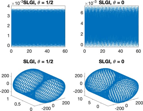
In Figure , we report the performance of the symplectic Lie group integrators (Equation15(15)
(15) )–(Equation17
(17)
(17) ) applied both on Equations (Equation21
(21)
(21) )–(Equation22
(22)
(22) ) with
,
and
(SLGI), and to Equations (Equation29
(29)
(29) )–(Equation32
(32)
(32) ) with
(SLGIKK). The methods with
attain order 2. In Figure , we show the energy error for the symplectic Lie group integrators with
and
integrating with stepsize h = 0.01 for 6000 steps.
Figure 1. Illustration of the heavy top, where CM is the centre of mass of the body, O is the fixed point, is the gravitational acceleration vector, and
follow the notation introduced in Section 3.4.1.
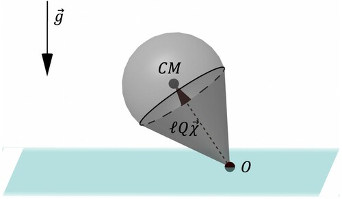
Figure 2. Symplectic Lie group integrators integration on the time interval . Left: 3D plot of
. Centre: components of
. The left and centre plots are computed with the same step-size. Right: verification of the order of the methods.
![Figure 2. Symplectic Lie group integrators integration on the time interval [0,1]. Left: 3D plot of MℓQ−1Γ0. Centre: components of QX. The left and centre plots are computed with the same step-size. Right: verification of the order of the methods.](/cms/asset/d4c820e0-eb02-4618-b144-27140c38c6ab/gcom_a_1966772_f0002_oc.jpg)
Figure 3. Symplectic Lie group integrators, long time integration, h = 0.01, 6000 steps.. Top: energy error, bottom 3D plot of .
4. Variable step size
One approach for varying the step size is based on the use of an embedded Runge–Kutta pair. This principle can be carried from standard Runge–Kutta methods in vector spaces to the present situation with RKMK and commutator-free schemes via minor modifications. We briefly summarize the main principle of embedded pairs before giving more specific details for the case of Lie group integrators. This approach is very well documented in the literature and goes back to Merson [Citation38] and a detailed treatment can be found in [Citation19, pp. 165–168].
An embedded pair consists of a main method used to propagate the numerical solution, together with some auxiliary method that is only used to obtain an estimate of the local error. This local error estimate is in turn used to derive a step size adjustment formula that attempts to keep the local error estimate approximately equal to some user defined tolerance in every step. Suppose the main method is of order p and the auxiliary method is of order
Footnote4 Both methods are applied to the input value
and yields approximations
and
respectively, using the same step size
. Now, some distance measureFootnote5 between
and
provides an estimate
for the size of the local truncation error. Thus
. Aiming at
in every step, one may use a formula of the type
(33)
(33)
where θ is a ‘safety factor’, typically chosen between 0.8 and 0.9. In case the step is rejected because
we can redo the step with a step size obtained by the same formula. We summarize the approach in the following algorithm
Here we have used again the safety factor θ, and the parameter α is generally chosen as .
4.1. RKMK methods with variable stepsize
We need to specify how to calculate the quantity in each step. For RKMK methods, the situation is simplified by the fact that we are solving the local problem (Equation6
(6)
(6) ) in the linear space
, where the known theory can be applied directly. So any standard embedded pair of Runge–Kutta methods described by coefficients
of orders
can be applied to the full dexpinv-equation (Equation6
(6)
(6) ) to obtain local Lie algebra approximations
,
and one uses, e.g.
(note that the equation itself depends on
). For methods which use a truncated version of the series for
one may also try to optimize performance by including commutators that are shared between the main method and the auxiliary scheme.
4.2. Commutator-free methods with variable stepsize
For the commutator-free methods of Section 2.2, the situation is different since such methods do not have a natural local representation in a linear space. One can still derive embedded pairs, and this can be achieved by studying order conditions [Citation44] as was done in [Citation12]. Now one obtains after each step two approximations and
on
both by using the same initial value
and step size
. One must also have access to some metric d to calculate
We give a few examples of embedded pairs.
4.2.1. Pairs of order
It is possible to obtain embedded pairs of order 3(2) which satisfy the requirements above. We present two examples from [Citation12]. The first one reuses the second stage exponential in the update
One could also have reused the third stage
in the update, rather than
.
It is always understood that the frozen vector fields are
.
4.2.2. Order
The procedure of deriving efficient pairs becomes more complicated as the order increases. In [Citation12], a low cost pair of order was derived, in the sense that one attempted to minimize the number of stages and exponentials in the embedded pair as a whole. This came, however, at the expense of a relatively large error constant. So rather than presenting the method from that paper, we suggest a simpler procedure at the cost of some more computational work per step, we simply furnish the commutator-free method of Section 2 by a third-order auxiliary scheme. It can be described as follows:
Compute
Compute an additional stage
5. The N-fold 3D pendulum
In this section, we present a model for a system of N connected three-dimensional pendulums. The modelling part comes from [Citation28], and here we study the vector field describing the dynamics, in order to re-frame it into the Lie group integrators setting described in the previous sections. The model we use is not completely realistic since, for example, it neglects possible interactions between pendulums, and it assumes ideal spherical joints between them. However, this is still a relevant example from the point of view of geometric numerical integration. More precisely, we show a possible way to work with a configuration manifold which is not a Lie group, applying the theoretical instruments introduced before.
The Lagrangian we consider is a function from to
. Instead of the coordinates
, where
, we choose to work with the angular velocities. Precisely,
and hence for any
there exist
such that
, which can be interpreted as the angular velocity of
. So we can assume without loss of generality that
(i.e.
) and pass to the coordinates
to describe the dynamics. In this section, we denote with
the masses of the pendulums and with
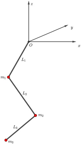
their lengths. Figure shows the case N = 3. We organize the section into three parts:
We define the transitive Lie group action used to integrate this model numerically,
We show a possible way to express the dynamics in terms of the infinitesimal generator of this action, for the general case of N joint pendulums,
We focus on the case N = 2, as a particular example. For this setting, we present some numerical experiment comparing various Lie group integrators and some classical numerical integrator. Then we conclude with numerical experiments on variable step size.
5.1. Transitive group action on
We characterize a transitive action for , starting with the case N = 1 and generalizing it to N>1. The action we consider is based on the identification between
, the Lie algebra of
and
. We start from the Ad-action of
on
(see [Citation23]), which writes
Since
, the Ad-action allows us to define the following Lie group action on
We can think of ψ as a Lie group action on
since, for any
, it maps points of
into other points of
. Moreover, with standard arguments (see [Citation43]), it is possible to prove that the orbit of a generic point
with
coincides with
In particular, when
is a unit vector (i.e.
), ψ allows us to define a transitive Lie group action on
which writes
To conclude the description of the action, we report here its infinitesimal generator which is fundamental in the Lie group integrators setting
We can extend this construction to the case N>1 in a natural way, i.e. through the action of a Lie group obtained from cartesian products of
and equipped with the direct product structure. More precisely, we consider the group
and by direct product structure we mean that for any pair of elements
denoted with
the semidirect product of
, we define the product ° on G as
With this group structure defined, we can generalize the action introduced for N = 1 to larger Ns as follows:
whose infinitesimal generator writes
where
and
. We have now the only group action we need to deal with the N-fold spherical pendulum. In the following part of this section, we work on the vector field describing the dynamics and adapt it to the Lie group integrators setting.
Figure 4. Threefold pendulum at a fixed time instant, with fixed point placed at the origin.
5.2. Full chain
We consider the vector field , describing the dynamics of the N-fold 3D pendulum, and we express it in terms of the infinitesimal generator of the action defined above. More precisely, we find a function
such that
We omit the derivation of F starting from the Lagrangian of the system, which can be found in the section devoted to mechanical systems on
of [Citation28]. The configuration manifold of the system is
, while the Lagrangian, expressed in terms of the variables
, writes
where
is the inertia matrix of the system,
is the
identity matrix, and
. Noticing that when i = j we get
we simplify the notation writing
where
is a symmetric block matrix defined as
The vector field on which we need to work defines the following first-order ODE:
By direct computation, it is possible to see that, for any
and
, we have
Therefore, there is a well-defined linear map
We can even notice that
defines a positive-definite bilinear form on this linear space, since
The last inequality holds because M is the inertia matrix of the system and hence it defines a symmetric positive-definite bilinear form on
, see, e.g. [Citation16].Footnote6 This implies the map
is invertible and hence we are ready to express the vector field in terms of the infinitesimal generator. We can rewrite the ODEs for the angular velocities as follows:
where
and
are N functions whose existence is guaranteed by the analysis done above. Indeed, we can set
and conclude that a mapping f from
to
such that
is the following one:
We will not go into the Hamiltonian formulation of this problem; however, we remark that a similar approach works even in that situation. Indeed, following the derivation presented in [Citation28], we see that for a mechanical system on
the conjugate momentum writes
and its components are still orthogonal to the respective base points
. Moreover, Hamilton's equations take the form
which implies that setting
we can represent even the Hamiltonian vector field of the N-fold 3D pendulum in terms of this group action.
5.2.1. Case N = 2
We have seen how it is possible to turn the equations of motion of a N-chain of pendulums into the Lie group integrators setting. Now we focus on the example with N = 2 pendulums. The equations of motion write
(35)
(35)
where
As presented above, the matrix
defines a linear invertible map of the space
onto itself:
We can easily see that it is well defined since
with
This map guarantees that if we rewrite the pair of equations for the angular velocities in (Equation35
(35)
(35) ) as
then we are assured that there exists a pair of functions
such that
Since we want
, we just impose
and hence the whole vector field can be rewritten as
with
and
Therefore, we can express the whole vector field in terms of the infinitesimal generator of the action of
as
through the function
5.3. Numerical experiments
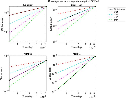
In this section, we present some numerical experiment for the N-chain of pendulums. We start by comparing the various Lie group integrators that we have tested (with the choice N = 2), and conclude by analysing an implementation of variable step size. Lie group integrators allow to keep the evolution of the solution in the correct manifold, which is when N = 2. Hence, we briefly report two sets of numerical experiments. In the first one, we show the convergence rate of all the Lie group integrators tested on this model. In the second one, we check how they behave in terms of preserving the two following relations:
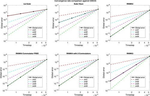
Figure presents the plots of the errors, in logarithmic scale, obtained considering as a reference solution the one given by the ODE45 method, with strict tolerance. Here, we used an exact expression for the function. However, we could obtain the same results with a truncated version of this function, keeping a sufficiently high number of commutators, or after some clever manipulations of the commutators (as with RKMK4 with 2 commutators, see Section 2.2). The schemes show the right convergence rates, so we can move to the analysis of the time evolution on
.
Figure 5. Convergence rate of the implemented Lie group integrators, based on global error considering as a reference solution the one of ODE45, with strict tolerance.
In Figure , we can see the comparison of the time evolution of the 2-norms of and
, for
. As highlighted above, unlike classical numerical integrators like the one implemented in ODE45 or the Runge–Kutta 4, the Lie group methods preserve the norm of the base components of the solutions, i.e.
. Therefore, as expected, these integrators preserve the configuration manifold. However, to complete this analysis, we show the plots making a similar comparison but with the tangentiality conditions.
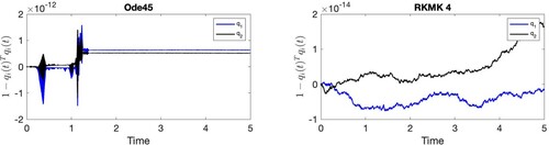
Indeed, in Figure we compare the time evolutions of the inner products
and
for
, i.e. we see if these integrators preserve the geometry of the whole phase space
. As we can see, while for Lie group methods these inner products are of the order of
and
, the ones obtained with classical integrators show that the tangentiality conditions are not preserved with the same accuracy.
Figure 6. Visualization of the quantity , i = 1, 2, for time
. These plots focus on the preservation of the geometry of
.
![Figure 6. Visualization of the quantity 1−qi(t)Tqi(t), i = 1, 2, for time t∈[0,5]. These plots focus on the preservation of the geometry of S2.](/cms/asset/b92e8e84-8725-409c-b3fb-8c43b419e967/gcom_a_1966772_f0006_oc.jpg)
We now move to some experiments on variable stepsize. In this last part, we focus on the RKMK pair coming from Dormand–Prince method (DOPRI 5(4) [Citation14]), which we denote with RKMK(5,4). The aim of the plots we show is to compare the same schemes, both with constant and variable stepsize. We start by setting a tolerance and solving the system with the RKMK(5,4) scheme. Using the same number of time steps, we solve it again with RKMK of order 5. These experiments show that, for some tolerance and some initial conditions, the step size's adaptivity improves the numerical approximation accuracy. Since we do not have an available analytical solution to quantify these two schemes' accuracy, we compare them with the solution obtained with a strict tolerance and ODE45. We compute such accuracy, at time T = 3, by means of the Euclidean norm of the ambient space .
Figure 7. Visualization of the inner product , i = 1, 2, for
. These plots focus on the preservation of the geometry of
.
![Figure 7. Visualization of the inner product qi(t)Tωi(t), i = 1, 2, for t∈[0,5]. These plots focus on the preservation of the geometry of Tqi(t)S2.](/cms/asset/80b2a8ed-b80e-4733-a940-b1ac7f0badb7/gcom_a_1966772_f0007_oc.jpg)
In Figure , we compare the performance of the constant and variable stepsize methods, where the structure of the initial condition is always the same, but what changes is the number of connected pendulums. The considered initial condition is , and all the masses and lengths are set to 1. From these experiments, we can notice situations where the variable step size beats the constant one in terms of accuracy at the final time, like the case N = 2 which we discuss in more detail afterwards.
Figure 8. Comparison of accuracy at final time (on the left) and step adaptation for the case N = 20 (on the right), with all pendulums of length .
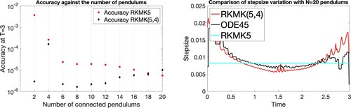
The results presented in Figure (left) do not aim to highlight any particular relation between how the number of pendulums increases or the regularity of the solution. Indeed, as we add more pendulums, we keep incrementing the total length of the chain since . Thus here we do not have any appropriate limiting behaviour in the solution as
. The behaviour presented in that figure seems to highlight an improvement in accuracy for the RKMK5 method as N increases. However, this is biased by the fact that when we increase N, to achieve the fixed tolerance of
with RKMKK(5,4), we need more time steps in the discretization. Thus, this plot does not say that as N increases, the dynamics becomes more regular; it suggests that the number of required timesteps increases faster than the ‘degree of complexity’ of the dynamics.
Figure 9. In these plots, we represent the six components of the solution describing the dynamics of the first mass (on the left) and of the second mass (on the right), for the case N = 2. We compare the behaviour of the solution obtained with constant stepsize RKMK5, the variable stepsize RKMK(5,4) and ODE45. (a) (b)
.
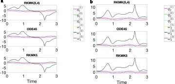
Figure 10. Comparison of accuracy at final time (on the left) and step adaptation for the case N = 20 (on the right), with all pendulums of length .
For the case N = 2, we notice a relevant improvement passing to variable stepsize. In Figures and we can see that, for this choice of the parameters, the solution behaves smoothly in most of the time interval, but then there is a peak in the second component of the angular velocities of both the masses, at . We can observe this behaviour both in the plots of Figure , where we project the solution on the 12 components and even in Figure (c). In the latter, we plot two of the vector field components, i.e. the second components of the angular accelerations
, i = 1, 2. They show an abrupt change in the vector field in correspondence to
, where the step is considerably restricted. Thus, to summarize, the gain we see with variable stepsize when N = 2 is motivated by the unbalance in the length of the time intervals with no abrupt changes in the dynamics and those where they appear. Indeed, we see that apart from a neighbourhood of
, the vector field does not change quickly. On the other hand, for the case N = 20, this is the case. Thus the adaptivity of the stepsize does not bring relevant improvements in the latter situation.
Figure 11. On the left, we compare the adaptation of the stepsize of RKMK(5,4) with the one of ODE45 and with the constant stepsize of RKMK5. In the centre, we plot the second component of the angular velocities , i = 1, 2, and we zoom in the last time interval
to see that the variable stepsize version of the method better reproduces the reference solution. On the right, we visualize the speed of variation of second component of the angular velocities. (a) Step adaptation, (b) Zoom at final times, (c) Values of
.
![Figure 11. On the left, we compare the adaptation of the stepsize of RKMK(5,4) with the one of ODE45 and with the constant stepsize of RKMK5. In the centre, we plot the second component of the angular velocities ωi(2), i = 1, 2, and we zoom in the last time interval t∈[2.1,3] to see that the variable stepsize version of the method better reproduces the reference solution. On the right, we visualize the speed of variation of second component of the angular velocities. (a) Step adaptation, (b) Zoom at final times, (c) Values of ω˙i(2)(t).](/cms/asset/173d8eef-e8b1-4a4f-9bb4-4b9c3b8650ca/gcom_a_1966772_f0011_oc.jpg)
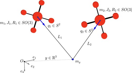
Figure 12. Two quadrotors connected to the mass point via massless links of lengths
.
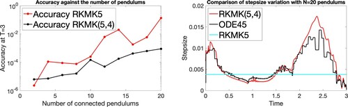
The motivating application behind our choice of this mechanical system has been some intuitive relation with a beam model, as highlighted in the introduction of this work. However, for this limiting behaviour to make sense, we should fix the length of the entire chain of pendulums to some L (the length of the beam at rest) and then set the size of each pendulum to . In this case, keeping the same tolerance of
for RKMK(5,4), we get the results presented in the following plot. We do not investigate more in detail this approach, which might be relevant for further work, however, we highlight that here the step adaptivity improves the results as we expected.
6. Dynamics of two quadrotors transporting a mass point
In this section, we consider a multibody system made of two cooperating quadrotor unmanned aerial vehicles (UAV) connected to a point mass (suspended load) via rigid links. This model is described in [Citation28,Citation29].
We consider an inertial frame whose third axis goes in the direction of gravity, but opposite orientation, and we denote with the mass point and with
the two quadrotors. We assume that the links between the two quadrotors and the mass point are of a fixed length
. The configuration variables of the system are: the position of the mass point in the inertial frame,
, the attitude matrices of the two quadrotors,
and the directions of the links which connect the centre of mass of each quadrotor respectively with the mass point,
. The configuration manifold of the system is
.
In order to present the equations of motion of the system, we start by identifying via left trivialization. This choice allows us to write the kinematic equations of the system as
(36)
(36)
where
represent the angular velocities of each quadrotor, respectively, and
express the time derivatives of the orientations
, respectively, in terms of angular velocities, expressed with respect to the body-fixed frames. From these equations, we define the trivialized Lagrangian
as the difference of the total kinetic energy of the system and the total potential (gravitational) energy, L = T−U, with:
and
where
are the inertia matrices of the two quadrotors and
are their respective total masses. In this system, each of the two quadrotors generates a thrust force, which we denote with
, where
is the magnitude, while
is the direction of this vector in the i th body-fixed frame, i = 1, 2. The presence of these forces make it a nonconservative system. Moreover, the rotors of the two quadrotors generate a moment vector, and we denote with
the cumulative moment vector of each of the two quadrotors. To derive the Euler–Lagrange equations, a possible approach is through Lagrange–d'Alambert's principle, as presented in [Citation28]. We write them in matrix form as
(37)
(37)
where
where
and
are respectively the orthogonal projection of
along
and to the plane
, i = 1, 2, i.e.
,
. These equations, coupled with the kinematic equations in (Equation36
(36)
(36) ), describe the dynamics of a point
Since the matrix
is invertible, we pass to the following set of equations:
(38)
(38)
6.1. Analysis via transitive group actions
We identify the phase space M with . The group we consider is
where the groups are combined with a direct-product structure and
is the additive group. For a group element
and a point
in the manifold, we consider the following left action:
The well-definiteness and transitivity of this action come from standard arguments, see, e.g. [Citation43]. The infinitesimal generator associated to
where
, writes
We can now focus on the construction of the function
such that
, where
is the vector field obtained combining Equations (Equation36
(36)
(36) ) and (Equation38
(38)
(38) ). We have
We have obtained the local representation of the vector field
in terms of the infinitesimal generator of the transitive group action ψ, hence we can solve for one time step
the IVP
and then update the solution
.
The above construction is completely independent of the control functions and hence it is compatible with any choice of these parameters.
6.2. Numerical experiments
We tested Lie group numerical integrators for a load transportation problem presented in [Citation29]. The control inputs are constructed such that the point mass asymptotically follows a given desired trajectory
, given by a smooth function of time, and the quadrotors maintain a prescribed formation relative to the point mass. In particular, the parallel components
are designed such that the payload follows the desired trajectory
(load transportation problem), while the normal components
are designed such that
converge to desired directions
(tracking problem in
). Finally,
are designed to control the attitude of the quadrotors.
In this experiment, we focus on a simplified dynamics model, i.e. we neglect the construction of the controllers for the attitude dynamics of the quadrotors. However, the full dynamics model can also be easily integrated, once the expressions for the attitude controllers are available.
In Figure , we show the convergence rate of four different RKMK methods compared with the reference solution obtained with ODE45 in MATLAB.
Figure 13. Convergence rate of the numerical schemes compared with ODE45.
In Figures –, we show results in the tracking of a parabolic trajectory, obtained by integrating the system (Equation37(37)
(37) ) with a RKMK method of order 4.
Figure 14. Snapshots at .
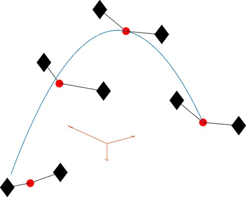
Figure 15. Components of the load position (in blue) and the desired trajectory (in red) as a function time.
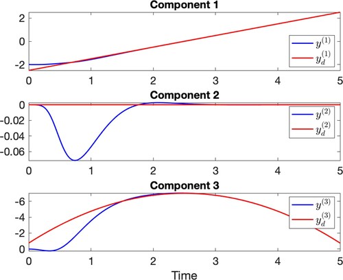
Figure 16. Deviation of the load position from the target trajectory.
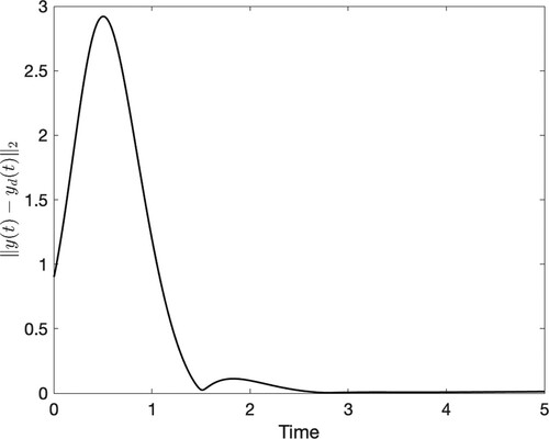
Figure 17. Direction error of the links.
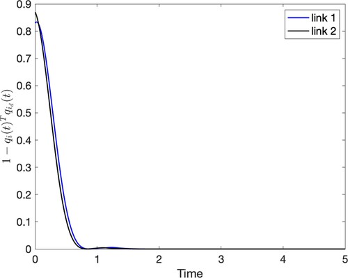
Figure 18. Preservation of the norms of .
7. Summary and outlook
In this paper, we have considered Lie group integrators with a particular focus on problems from mechanics. In mathematical terms, this means that the Lie groups and manifolds of particular interest are ,
as well as the manifolds
and
. The abstract formulations by, e.g. Crouch and Grossman [Citation11], Munthe-Kaas [Citation41] and Celledoni et al. [Citation6] have often been demonstrated on small toy problems in the literature, such as the free rigid body or the heavy top systems. But in papers like [Citation4], hybrid versions of Lie group integrators have been applied to more complex beam and multi-body problems. The present paper is attempting to move in the direction of more relevant examples without causing the numerical solution to depend on how the manifold is embedded in an ambient space, or the choice of local coordinates.
It will be the subject of future work to explore more examples and to aim for a more systematic approach to applying Lie group integrators to mechanical problems. In particular, it is of interest to the authors to consider models of beams that could be seen as a generalization of the N-fold pendulum discussed here.
Disclosure statement
No potential conflict of interest was reported by the author(s).
Additional information
Funding
Notes
1 If the Lie group action is smooth, a map f of the same regularity as F can be found [Citation53].
2 is obtained from the natural symplectic form on
(which is a differential two-form), defined as
by right trivialization.
3 The Euler–Poincaré equations are Euler–Lagrange equations with respect to a Lagrange–d'Alembert principle obtained taking constraint variations.
4 In this paper, we will assume in which case the local error estimate is relevant for the approximation
.
5 There are many options for how to do this in practice, and the choice may also depend on the application. E.g. a Riemannian metric is a natural and robust alternative here.
6 It follows from the definition of the inertia tensor, i.e.
Moreover, in this situation it is even possible to explicitly find the Cholesky factorization of the matrix M with an iterative algorithm.
References
- M. Arnold and O. Brüls, Convergence of the generalized-α scheme for constrained mechanical systems, Multibody Syst. Dyn. 18(2) (2007), pp. 185–202.
- M. Arnold, O. Brüls, and A. Cardona, Error analysis of generalized-α Lie group time integration methods for constrained mechanical systems, Numer. Math. 129(1) (2015), pp. 149–179.
- G. Bogfjellmo and H. Marthinsen, High-order symplectic partitioned Lie group methods, Found. Comput. Math. 16(2) (2015), pp. 493–530.
- O. Bruls and A. Cardona, On the use of lie group time integrators in multibody dynamics, J. Comput. Nonlinear Dyn. 5(3) (2010), p. 031002.
- F. Casas and B. Owren, Cost efficient lie group integrators in the RKMK class, BIT Numer. Math.43(4) (2003), pp. 723–742.
- E. Celledoni, A. Marthinsen, and B. Owren, Commutator-free lie group methods, Future Generation Comput. Syst. 19 (2003), pp. 341–352.
- E. Celledoni, H. Marthinsen, and B. Owren, An introduction to Lie group integrators–basics, new developments and applications, J. Comput. Phys. 257(part B) (2014), pp. 1040–1061.
- E. Celledoni and B. Owren, Lie group methods for rigid body dynamics and time integration on manifolds, Comput. Methods Appl. Mech. Eng. 192(3-4) (2003), pp. 421–438.
- J. Ćesić, V. Jukov, I. Petrovic, and D. Kulić, Full Body Human Motion Estimation on Lie Groups using 3D Marker Position Measurements, Proceedings of the IEEE-RAS International Conference on Humanoid Robotics, Cancun, 15–17 November 2016, 2016.
- S.H. Christiansen, H.Z. Munthe-Kaas, and B. Owren, Topics in structure-preserving discretization, Acta Numer. 20 (2011), pp. 1–119.
- P.E. Crouch and R. Grossman, Numerical integration of ordinary differential equations on manifolds, J. Nonlinear Sci. 3 (1993), pp. 1–33.
- C. Curry and B. Owren, Variable step size commutator free Lie group integrators, Numer. Algorithms82(4) (2019), pp. 1359–1376.
- F. Diele, L. Lopez, and R. Peluso, The Cayley transform in the numerical solution of unitary differential systems, Adv. Comput. Math. 8(4) (1998), pp. 317–334.
- J.R. Dormand and P.J. Prince, A family of embedded Runge–Kutta formulae, J. Comput. Appl. Math. 6(1) (1980), pp. 19–26.
- K. Engø and S. Faltinsen, Numerical integration of Lie–Poisson systems while preserving coadjoint orbits and energy, SIAM J. Numer. Anal. 39(1) (2001), pp. 128–145.
- H. Goldstein, C.P. Poole, and J. Safko, Classical Mechanics, Pearson, Essex, 2013.
- V. Guillemin and S. Sternberg, The moment map and collective motion, Ann. Phys. 127 (1980), pp. 220–253.
- E. Hairer, C. Lubich, and G. Wanner, Geometric Numerical Integration, Springer Series in Computational Mathematics, Vol. 31, Springer, Heidelberg, 2010. Structure-Preserving Algorithms for Ordinary Differential Equations, Reprint of the Second (2006) Edition.
- E. Hairer, S.P. Nørsett, and G. Wanner, Solving Ordinary Differential Equations I: Nonstiff Problems, 2nd ed., Springer-Verlag, Berlin, 1993.
- J. Hall and M. Leok, Lie group spectral variational integrators, Found. Comput. Math. 17(1) (2017), pp. 199–257.
- F. Hausdorff, Die symbolische exponentialformel in der gruppentheorie, Leipziger Ber. 58 (1906), pp. 19–48.
- H.M. Hilber, T.J.R. Hughes, and R.L. Taylor, Improved numerical dissipation for time integration algorithms in structural dynamics, Earthquake Eng. Structural Dyn. 5(3) (1977), pp. 283–292. cited By 1683.
- D. Holm, Geometric Mechanics: Part II: Rotating, Translating and Rolling, World Scientific Publishing Company, Singapore, 2008.
- D. Holm, J. Marsden, and T. Ratiu, The Euler--Poincaré equations and semidirect products with applications to continuum theories, Adv. Math. 137 (1998), pp. 1–81.
- S. Holzinger and J. Gerstmayr, Time integration of rigid bodies modelled with three rotation parameters, Multibody Sys Dyn (2021), doi:https://doi.org/10.1007/s11044-021-09778-w
- A. Iserles, H.Z. Munthe-Kaas, S.P. Nørsett, and A. Zanna, Lie-group methods, Acta Numer. 9 (2000), pp. 215–365.
- T. Lee, M. Leok, and N.H. McClamroch, Lie group variational integrators for the full body problem, Comput. Methods Appl. Mech. Eng. 196(29-30) (2007), pp. 2907–2924.
- T. Lee, M. Leok, and N.H. McClamroch, Global Formulations of Lagrangian and Hamiltonian Dynamics on Manifolds, in A Geometric Approach to Modeling and Analysis, Interaction of Mechanics and Mathematics, Springer, Cham, 2018.
- T. Lee, K. Sreenath, and V. Kumar, Geometric Control of Cooperating Multiple Quadrotor UAVs with a Suspended Payload. Proceedings of 52nd IEEE Conference on Decision and Control, Firenze, Italy. IEEE, 2013. pp. 5510–5515.
- T. Leitz and S. Leyendecker, Galerkin Lie-group variational integrators based on unit quaternion interpolation, Comput. Methods Appl. Mech. Eng. 338 (2018), pp. 333–361.
- N.E. Leonard and J.E. Marsden, Stability and drift of underwater vehicle dynamics: mechanical systems with rigid motion symmetry, Phys. D 105(1–3) (1997), pp. 130–162.
- D. Lewis and J.C. Simo, Conserving algorithms for the dynamics of Hamiltonian systems of Lie groups, J. Nonlinear Sci. 4 (1994), pp. 253–299.
- A. Lundervold and H.Z. Munthe-Kaas, On Algebraic Structures of Numerical Integration on Vector Spaces and Manifolds, in Faà di Bruno Hopf Algebras, Dyson-Schwinger Equations, and Lie-Butcher Series, volume 21 of IRMA Lect. Math. Theor. Phys., European Mathematical Society Publishing, Zürich, 2015, pp. 219–263.
- A. Müller, Coordinate mappings for rigid body motions, ASME J. Comput. Nonlinear Dyn. 12(2) (2017), p. 021010.
- J.E. Marsden and T.S. Ratiu, Introduction to Mechanics and Symmetry, Springer-Verlag, New York, NY, 1994.
- J.E. Marsden, T. Ratiu, and A. Weinstein, Semi-direct products and reduction in mechanics, Trans. Am. Math. Soc. 281 (1884), pp. 147–77.
- J.E. Marsden and T.S. Ratiu, Introduction to Mechanics and Symmetry, 2nd ed., Texts in Applied Mathematics, Vol. 17, Springer-Verlag, New York, NY, 1999.
- R.H. Merson, An Operational Method for the Study of Integration Processes, Proc. Symp. Data Processing, Weapons Res. Establ. Salisbury, 1957.
- J. Moser and A.P. Veselov, Discrete versions of some classical integrable systems and factorization of matrix polynomials, Comm. Math. Phys. 139(2) (1991), pp. 217–243.
- H. Munthe-Kaas, Runge–Kutta methods on Lie groups, BIT 38(1) (1998), pp. 92–111.
- H. Munthe-Kaas, High order Runge–Kutta methods on manifolds, Appl. Numer. Math. 29 (1999), pp. 115–127.
- H. Munthe-Kaas and B. Owren, Computations in a free Lie algebra, Phil. Trans. Royal Soc. A 357 (1999), pp. 957–981.
- P.J. Olver, Applications of Lie Groups to Differential Equations, Vol. 107, Springer Science & Business Media, New York, NY, 2000.
- B. Owren, Order conditions for commutator-free Lie group methods, J. Phys. A 39(19) (2006), pp. 5585–5599.
- B. Owren and A. Marthinsen, Integration methods based on canonical coordinates of the second kind, Numer. Math. 87(4) (2001), pp. 763–790.
- B. Owren, Lie Group Integrators. in Discrete Mechanics, Geometric Integration and Lie-Butcher Series, volume 267 of Springer Proc. Math. Stat., Springer, Cham, 2018, pp. 29–69.
- J. Park and W. Chung, Geometric integration on Euclidean group with application to articulated multibody systems, IEEE Trans. Robot. 21(5) (2005), pp. 850–863.
- T. Ratiu, Euler-Poisson equations on Lie algebras and the n-dimensional heavy rigid body, Proc. Nat. Acad. Sci. USA 78(3) (1981), pp. 1327–1328.
- A. Saccon, Midpoint rule for variational integrators on Lie groups, Int. J. Numer. Methods Eng. 78(11) (2009), pp. 1345–1364.
- J.C. Simo and L. Vu-Quoc, On the dynamics of finite-strain rods undergoing large motions – a geometrically exact approach, Comput. Methods Appl. Mech. Eng. 66 (1988), pp. 125–161.
- A.P. Veselov, Integrable systems with discrete time, and difference operators, Funktsional. Anal. i Prilozhen. 22(2) (1988), pp. 1–13.
- A.M. Vinogradov and B. Kupershmidt, The structure of Hamiltonian mechanics, Funktsional. Anal. i Prilozhen. 32 (1977), pp. 177–243.
- F.W. Warner, Foundations of Differentiable Manifolds and Lie Groups, GTM 94, Springer-Verlag, New York, NY, 1983.
- V. Wieloch and M. Arnold, BDF integrators for constrained mechanical systems on Lie groups, J. Comput. Appl. Math. 387 (2019), p. 112517.