
 ?Mathematical formulae have been encoded as MathML and are displayed in this HTML version using MathJax in order to improve their display. Uncheck the box to turn MathJax off. This feature requires Javascript. Click on a formula to zoom.
Abstract
Since the complex engineered system involves multi-disciplinary, co-simulation is the key technique to the performance analysis. However, the co-simulation is hindered by heterogeneous sub-systems and ununified environments. In this paper, a Cognitive Twin (CT) to support the co-simulation of the complex engineered system is introduced. It is a generic approach that can be applied in many complex engineered systems such as the aerospace field, automotive system, the Internet of Things, manufacturing systems, etc. CT adopts an ontology model to develop cognition capability based on CT architecture. Then, a unified ontology modelling approach based on GOPPRR (graph, object, point, property, role, relationship) is presented to support an accurate semantic description of the topology between digital entities that use FMI 2.0 as the interconnection standard. Besides, four types of information are included in the ontology model to form the knowledge in co-simulation. Finally, the co-simulation is automatically executed using the cognition capability. Furthermore, a master-slave algorithm is deployed to establish a unified co-simulation environment. The flexibility of CT is evaluated using a gas turbine case. The results demonstrate that the complication in the co-simulation of complex engineered systems is solved by the unified ontology modelling approach and the architecture of CT.
1. Introduction
There are multiple interactions between different sub-systems in a complex engineered system (Rind Citation1999). With the continuous increase of the functions in sub-systems, the life cycle is simulated, verified, predicted, and controlled using Digital Twin (DT) in most complex engineered systems (Cameron, Crawley, and Selva Citation2016). The DT is constructed with the digital entity of the physical entity, and co-simulation is executed to analyze the performance of complex engineered systems.
Co-simulation is an emerging enabling modus to combine different tools, digital entities, and disciplines for the simulation of a complex engineered system. Co-simulation refers to a means of analysing the performance of virtual prototypes by using simulation software of different disciplines. It deals with the intersection of multidisciplinary information of complex products and integrates models of different fields efficiently and ensures the stability of data interaction. The distributed simulation and integrated simulation are the two types of co-simulation methods. For the former type, systems and applications run at different locations. It usually has hardware in the loop. For the latter type, simulation tools and simulation models are integrated into one simulation system.
Co-simulation plays a transformative role in not only how complex engineered systems are designed but also how the modularity of multi-disciplinary systems is advanced to tackle fundamental barriers (Rasheed, San, and Kvamsdal Citation2019). However, there are still some general challenges to be solved. First, the limited interoperability of the tools becomes major hindrances in model integration (Karhela, Villberg, and Niemistö Citation2012). Second, the co-simulation environment is diverse in different fields such as mechanical, thermal, electrical, and electronic (Neema et al. Citation2014). Third, the information type of digital entities is inconsistent due to the separate establishment. Moreover, the integration of these simulation models wastes a lot of time ascribed to the complex topology between digital entities (Hemingway et al. Citation2012). These challenges are imminent for complex engineered systems with the co-simulation process.
With the purpose of solving the challenge of integration difficulty, ununified co-simulation environment, and diversity co-simulation information, CT is proposed as DT with augmented semantic capabilities to identify the dynamics of digital entity evolution, deepen the understanding of interrelationships between digital entities, and enhance the decision-making based on DT (Lu et al. Citation2020). Several researchers proposed semantic technology to support the co-simulation of their digital entities. Ontology is a semantic technology, widely used to formally express knowledge in co-simulation. For instance, the ontology of the petroleum plant system has been designed and implemented to monitor the petroleum plant shutdown process (Elhdad, Chilamkurti, and Torabi Citation2013). An ontology-based methodology has been adopted to integrate real data in the railway domain (Verstichel et al. Citation2011). An architecture based on ontology has been proposed to support team design and optimise the design process in multi-disciplinary systems (Chira et al. Citation2006). These studies have applied ontology-based technology in the design and simulation of the complex engineered system while the ontology was not combined with the simulation implementation level.
In this paper, the CT is developed to support the co-simulation of a complex engineered system. The topology between digital entities is formalised by establishing a unified ontology modelling method in CT. The CT not only expresses the diverse knowledge of co-simulation in a unified way but also supports the rapid integration of digital entities to execute in a unified co-simulation environment. The main contributions of this paper are summarised as follows.
Develop CT to support the co-simulation of complex engineered systems. Four types of information are included in ontology to form the knowledge used in co-simulation. The architecture of the CT is established to develop the cognitive capability, including co-simulation capability for executing co-simulation automatically and reasoning capability for analysing results.
Support the rapid integration of complex engineered systems’ digital entities. The unified modelling approach based on ontology is adopted to formalise the topology between sub-systems of complex engineered systems.
Establish a unified simulation environment to execute co-simulation. The co-simulation between heterogenous digital entities is automatically implemented using the CT architecture developed. The CT provides a unified simulation environment based on a co-simulation algorithm for the implementation of the co-simulation progress.
The rest of this paper is organised as follows. First, the related work about co-simulation and ontology support co-simulation in complex engineered systems is reviewed in Section 2. Then, the definition and architecture of the CT for supporting co-simulation are illustrated in Section 3. Next, the unified ontology modelling approach and co-simulation approach enabled by CT are investigated in Section 4. Afterward, the evaluation of CT for supporting co-simulation is analysed through a complex engineered system case in Section 5. Finally, the conclusion is drawn in Section 6.
2. Related works
In this section, the co-simulation methods used by several researchers are first reviewed. Then the co-simulation with ontology is discussed. And the main challenges in the co-simulation method of complex engineered systems are analysed.
2.1. Co-simulation in complex engineered systems
Two types of co-simulation types have been provided considering the complex engineered systems equipped with multi-disciplinary sub-systems: the distributed co-simulation and the integrated co-simulation.
The distributed co-simulation method implement co-simulation by general standards, typically High Level Architecture (HLA). The High Level Architecture (HLA) defines global software execution specifications for the interaction of different federates that are composed of distributed simulations and software applications (HLA Working Group Citation2000). Zhiying Tu et al. (Tu et al. ) present an approach on the presentation of the HLA web-enabled federates to fulfil the web service for implement distributed co-simulation of a car. Awais et al. (Awais et al. Citation2013) realise a distributed hybrid co-simulation by combining HLA and FMI. HLA is responsible for the data interaction and time management of co-simulation, and FMI is responsible for the generation of federate. These studies show that distributed simulation is still mainly focused on the development of communication level and does not consider the simulation operation of complex systems from the system level.
The integrated co-simulation approaches between digital entities of the multi-disciplinary sub-systems are divided into two types: The specific interface between different kinds of software is established according to the simulation target. For instance, Millwater et al. (Millwater, Ocampo, and Crosby Citation2019) built the interface between finite element models (FEM) and Computational Fluid Dynamics (CFD) to finish co-simulation. The co-simulation of aircraft maintenance is fulfilled as multi-source heterogeneous data are processed, so as to provide life prediction. Seshadri et al. (Seshadri and Krishnamurthy Citation2017) obtained the co-simulation results by establishing the communication between finite element analysis software Abaqus and Structural Health Management (SHM) system tools. Bajaj et al. (Bajaj, Cole, and Zwemer Citation2016) proposed the integration of system engineering and mechanical design based on Computer-Aided Engineering (CAE) and Matlab simulation interface. Ríos et al. (Ríos et al. Citation2016) designed a co-simulation architecture based on Dassault Systèmes V6 simulation to support design in aircraft models. Tuegel et al. (Tuegel Citation2012) developed a co-simulation system based on the damage and durability simulator (DDSim) simulation software and finite element models to predict maintenance needs. It is revealed that the method of establishing a specific interface to fulfil co-simulation is laborious due to the various simulation tools, and the reusability of the method is deficient owing to the lack of standards.
Another co-simulation approach adopts the same interface standard for every digital entity. There are open-source standards for co-simulation. For instance, the standard CAPEOPEN was used to connect simulator components using concepts of the unit (Peshev and Livingston Citation2013). The standard is generally employed in the sequential modular approach and is not commonly accepted by engineering. Currently, the Functional Mockup Interface (FMI) was provided to solve the integration problems in co-simulation using a standardised specification for the integration of simulation models, tools, and solver. This specification has its origin in the Modelica community (Karhela, Villberg, and Niemistö Citation2012). FMI was proposed and promoted in 2012. Besides, a model distributed in one ZIP file is called Functional Mock-up Unit (FMU), which contains all required model equations and all object libraries or dynamic link libraries. The specification is generally used in the co-simulation of complex engineered systems. For example, Ryan Magargle et al. (Magargle et al. Citation2017) applied the Modelica modelling language and FMI to couple models from different domains in Simplier for the co-simulation in the braking system. Nouidui et al. (Nouidui et al. Citation2019) developed a co-simulation platform based on FMI, called CyDER (A Cyber Physical Co-simulation Platform for Distributed Energy Resources), which integrates various domain-specific simulation tools.
These researches indicate that the integration of multi-disciplinary models can be finished by the same interface standard. However, the FMI specification just provides an interface of simulation models. The integration of digital entities is a complex and professional process due to the complex topology between them. Their interrelationships become more complicated with the digital entities updating across the lifecycle. Therefore, an effective relationship expression mechanism of the digital entities must be established to illustrate the internal connection and facilitate their rapid integration. Besides, the co-simulation environment of digital entities is diverse owing to the diversity of co-simulation methods. Thus, it is difficult to guarantee the reliability of the co-simulation results given the different communication steps in the ununified co-simulation environment.
2.2. Ontology supporting co-simulation
To bridge the gap in knowledge expression of interrelationship, several researchers envisioned ontology to describe the topology of the digital entities in the complex engineered system (Lu and Wang Citation2019). Ontology models allow capturing the digital entities intuitively with standardised ontology languages. Based on ontology, semantic analysis of knowledge enhancement can be conducted to support co-simulation, and several stages of co-simulation are covered with semantic models (Kharlamov et al. Citation2018).
For the design stage of the co-simulation, Brandt et al. (Brandt et al. Citation2006) provided information management and integration platform for design processes. Their approach is a flexible ontology-based schema with formally defined semantics that enable the capture of co-simulation knowledge. Fatfouta et al. (Fatfouta and Le-Cardinal J Citation2021) addressed a collaborative approach to develop ontology-based knowledge management for supporting simulation-aided design. Their approach used an ontology-based model that structures and formalises the formal knowledge and tacit knowledge related to design simulation resolution. Li Y et al. (Li, Tao, and Wotawa Citation2020) proposed an approach for taking ontologies to describe the environment of autonomous vehicles, then converts it to test cases that are used in a simulation environment.
For the digital entity generating stage of the co-simulation, Boussuge et al. (Boussuge et al. Citation2019) proposed a new approach to capture ‘simulation intent’ as an ontology-based application. The approach is adopted to capture high-level modelling and characterise the simulation intent into a knowledge-based CAE model, accelerating the generation of CAE models from CAD assemblies. Bohács et al. (Bohács and Rinkács Citation2017) presented an ontology-driven sub-system-based approach for structural adaptation in manufacturing. Through the novel approach, the simulation model can adapt its structure without the necessity of manual interaction by automated ontology-matching in the simulation environment. Bao Q et al. (Bao et al. Citation2020) used the ontology model to describe the assembly constrain relationships. The designing information in the ontology model was obtained to modelling a part digital twin.
For the data analysis stage of the co-simulation, Peter et al. (Szulman et al. Citation2005) presented an ontology-based reference model approach to solve the syntactical, structural, and even semantical differences of output and expected data of engineers. In the reference ontology model, attribute bridges between several ontology fragments are defined. Wei et al. (Wei et al. Citation2012) designed a semi-automatic construction method for domain professional ontology from web resources to automatically extract and store structured data through a programme and build pattern mapping between relational database and ontology through human–computer interaction. Nordahl et al. (Nordahl et al. Citation2020) present an ontology for automatically connecting variables of different models while complying with the FMI standard in co-simulations. The key idea is to build an ontology to reason connections between models.
In addition to the use of ontology and semantic techniques in different stages of simulation, semantic techniques at the co-simulation system level have been widely explored. Schwarz et al. (Schwarz et al. Citation2019) proposed an approach to ontological integration of domain knowledge in co-simulation. A semantic diagram in form of a mind map is used for modelling the information model. This approach hand domain knowledge in the planning, execution, and evaluation of interdisciplinary co-simulation based on ontologies that aim to allow the high-level planning of simulation scenarios. Besides, they propose an approach for assisting the user in the development of co-simulation scenarios by using an information model, a component catalog implemented in a Semantic Media Wiki, and Semantic Web technologies (Schwarz, Steinbrink, and Lehnhoff Citation2019). The information model describes the goals of a simulation, tasks of the simulation, and data interaction between simulation models. Teixeira et al. (Teixeira et al. Citation2020) developed an application ontology that supports the definition of co-simulation scenarios. The ontology represents the required knowledge to support the interoperability among the different considered systems. The ontology acts as a facilitator between heterogeneous tools, enabling them to share vocabularies and concepts, and thus collaborate in co-simulation. Elgharbawy et al. (Elgharbawy et al. Citation2019) present an adaptive verification framework for the automotive system based on ontologies and data-mining techniques. The ontology is used to generate a systematic test case co-simulation scenario description. Benjamin et al. (Benjamin, Patki, and Mayer Citation2006) proposed an ontology-based solution framework for simulation modelling and analysis. This framework chose the appropriate components to reduce the effort needed for developing and deploying distributed simulation applications.
These studies take ontology as the knowledge expression method to describe domain knowledge and co-simulation knowledge by establishing own vocabularies and relationships. However, they did not emphasize the unity of ontology modelling methods. Furthermore, the information included in the ontology is difficult to provide adequate support for co-simulation because the various information during the execution of the simulation is not considered.
Previous works suggest that there are still some problems to be solved.
Ununified co-simulation environment. The effectiveness of ontology for information management in systems has been recognised by engineers. However, the information in the ontology is rarely adopted to automatically execute co-simulation scenarios. Besides, diverse co-simulation tools are hindering the construction of a unified simulation environment. Thus, a unified co-simulation environment is needed to execute the co-simulation.
Various ontology modelling approaches. Various ontology modelling approaches have been developed for stages of the co-simulation of a complex engineered system. The lack of regularity makes ontology models difficult to be reused. Thus, a unified ontology modelling approach is required to express the knowledge for automatic integration and co-simulation. The modelling approach should include all the information in the life cycle of the complex engineered system.
3. Cognitive twin supporting co-simulation
In this section, the CT of the complex engineered systems is first defined. Then, the differences between CT and DT are introduced. Finally, the architecture of the CT is proposed to develop the construct of cognition capability.
3.1. Definition of cognitive twin
To detect and predict product performance during the life cycle, Professor Michael Grieves of the University of Michigan in the United States first proposed the concept of DT in 2003 for product life cycle management (Grieves Citation2003). DT is defined by NASA as an integrated multi-physics, multiscale simulation of a vehicle, or system with the best available physical models to mirror the life of its corresponding flying twin (Shafto et al. Citation2012). As one of the essential supporting technologies for the construction of cyber-physical space (CPS), DT has been applied in many fields such as aerospace (Shafto et al. Citation2012), intelligent manufacturing (Psarommatis Citation2021), supply chain (Chen et al. Citation2020), and the Internet of Things (Chen et al. Citation2019).
DT is a digital entity of a physical entity, and CT is the function extension of DT. The relationship between CT and DT is illustrated in Figure . CT is proposed as DT with augmented semantic capabilities to identify the topology of the sub-systems included in the complex engineered system (Lu et al. Citation2021). The cognition capability equipped by CT is to enhance the understanding of interrelationships between digital entities and thus automatically support co-simulation.
Figure 1. The relationship between CT and DT.
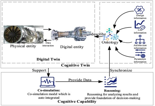
Compared with DT, a unified knowledge expression model of the digital entities, which is the ontology model, is added to CT. CT adopts the system-level ontology to describe the topology of digital entities. Besides, design information, life information, architecture information, and parameters information are included in ontology to form the knowledge used in the life cycle of systems. The functional difference between CT and DT is exhibited in Table .
Table 1. The functional difference between CT and DT.
The differences and meanings of the four types of information are introduced below.
Design information: Design information refers to the information of sub-systems in the design process of digital entities. The functional definition of the sub-systems, the principles, the designer information, and the generation tools of digital entities are summarised and transformed into general ontology information.
Life information: Life information suggests the version iteration information in the iterative process of the digital entity. According to the requirements of complex products, it is driven by the sub-system update function or a certain time point. The digital entity version of all sub-systems would be checked and updated to provide information for version management.
Architecture information: Architecture information mainly indicates the topology information between digital entities in a complex system and associated information between subsystems. Architecture information is used to complete the rapid integration of digital entities by providing the topology.
Parameter information: Parameter information represents the information of variables included in the complex system, such as the initial value, variable name in each sub-system, and the co-simulation time of the complex system. Moreover, the co-simulation results also belong to the parameter information.
These four types of information are employed to form the knowledge for supporting co-simulation and to verify the correctness of the co-simulation results. As indicated in Figure , CT executed the co-simulation model which is auto integrated, and the co-simulation results are provided to the reasoning for analysis. Besides, cognitive capability, including co-simulation capability and reasoning capability, is developed during the process of CT building. The content of the cognitive capability is detailed as follows.
Co-simulation capability. A unified approach is adopted in CT to build an ontology model of digital entities. The reliability of the model is improved through the establishment of the unified standard of ontology. A complete knowledge base is formed for subsequent co-simulation. Besides, an architecture-driven approach is employed in CT to achieve efficient integration between digital entities. Particularly, engineers would spend less time on digital entity integration using CT once the sub-systems of the system are replaced and the version of the digital entity is iterated. Furthermore, a co-simulation environment is also included for executing the co-simulation scenario. It has achieved the effect of digital entity version management and rapid integration.
Reasoning capability. The simulation results are analysed by the reasoning capabilities in CT, where the existing knowledge is used to analyze and continuously iteratively update knowledge. Ontology knowledge stores the simulation results in an associative form, improves the verification speed of simulation results, and enhances the scalability of ontology knowledge. Moreover, ontology knowledge can be understood by engineers and computers, contributing to the improvement of human–computer interaction capabilities.
3.2 Cognitive twin architecture for co-simulation
The architecture of CT is divided into three parts: unified ontology modelling, co-simulation, and result reasoning. The architecture of CT is illustrated in Figure . The ontology model includes the design information, life information, architecture information, and parameters information mentioned above. Due to the complexity and diversity of information, ontology integrates information according to Classes, Object Properties, and Data properties. The semantic modelling approach should be unified to represent the topology between models of digital entities. A unified ontology modelling approach, named GOPPRR (Graph, Object, Port, Property, Relationship, and Role), is proposed to formalise the ontology modelling process for the co-simulation process. Then, an ontology model is established by the GOPPRR modelling approach. The knowledge needed during co-simulation is formed using the Ontology model to support the automatic integration of digital entities.
The co-simulation scenario refers to the co-simulation requirement of the complex engineered system.
Figure 2. Cognitive Twin Architecture.
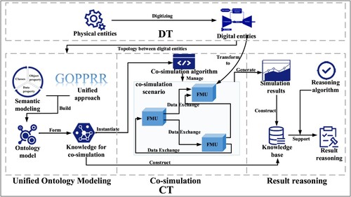
According to previous works, FMI is taken as the interconnection standard of simulation models. The digital entities of sub-systems are transformed into FMUs. The sub-systems in the co-simulation scenario can be rapidly integrated using the knowledge in the ontology. Then, a co-simulation algorithm is developed to build a unified simulation environment for executing the integrated sub-systems. The co-simulation scenario of the complex system is built and executed by instantiating the co-simulation algorithm.
When the co-simulation process is finished, the final simulation results are reasoned based on the ontology. Traditional FMU-based co-simulation results usually need to be extracted manually, and the simulation results of a certain port are difficult for people to understand in non-related sub-systems. The port has only a simplified name to provide limited information to engineers. Given the above problems, the simulation results of each port are automatically extracted and combined with the knowledge in the ontology to form a knowledge base. Then, the knowledge in ontology and simulation results are synthetically used in reasoning.
As revealed from Figure , the use of CT in complex engineered systems for co-simulation is reflected from the following perspectives. (1) A unified semantic modelling approach is employed to create an exact ontology model of digital entities and form the knowledge used in co-simulation of the complex engineered system. (2) The co-simulation algorithm is executed to generate the unity of the simulation environment with the FMUs transformed by the digital entities. (3) The simulation results generated by the co-simulation scenario are extracted to build the knowledge base with the knowledge in the ontology. Moreover, the knowledge would support reasoning by the reasoning algorithm.
4. Ontology design and co-simulation for constructing CT
In this section, the system knowledge representation is first explored to integrate digital entities of the complex system. A unified ontology modelling approach is adopted to clearly express the topology between digital entities. Then, a co-simulation approach of complex engineered systems is investigated to solve the co-simulation challenges mentioned above. Finally, a reasoning method for analysing the co-simulation results is developed to support reasoning simulation results in complex engineered systems.
4.1 Unified ontology modeling
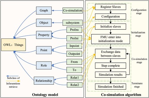
Ontology equips data with a certain physical meaning and represents the relationship between these meanings. It is the way for engineers to connect computer representation with the co-simulation process. The problem of representing the relationship is revealed across different metamodels that use properties (Kelly and Tolvanen Citation2008). Depending on the number of subsystems, the interconnections and configurations of subsystems become complex. Thus, a formal, clear, and detailed description of the shared conceptual ontology is explored. The established ontology enables domain experts and digital entities to share a consensus information structure. Besides, the ontology realises knowledge reuse and analysis by reasoning. A dedicated layer of digital entities abstraction is established based on an approach named GOPPRR. The ontology modelling of the complex system is implemented with the six basic elements of Graph, Object, Point, Property, Role, and Relationship (Lu et al. Citation2021). The relationship between GOPPRR is exhibited in Figure .
Figure 3. The relationship between GOPPRR.
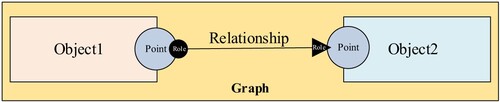
The Graph includes the other five elements. Object1 connects Object2 through Point and Relationship. The Roles from different Point connect together. The specific instructions on GOPPRR are provided in Table .
Table 2. The concept of the GOPPRR modelling method.
Web Ontology Language (OWL) is developed by W3C for the semantic description of ontology. OWL is applied to design a complete ontology based on the GOPPRR approach. The concept of GOPPRR is performed in the ontology to describe co-simulation scenarios. Firstly, the ontology of complex engineered systems is formalised by defining classes and class attributes. The concepts of GOPPRR are transformed into the Classes in the OWL. Secondly, the properties are defined between the classes. The relationships between GOPPRR concepts are defined as the Object Properties. Finally, the definition of Data Properties is described. The value of the Data Properties is to support the generation of the co-simulation code.
By establishing ontology with the GOPPRR approach, the relationships between each individual (Instance of the Classes) are formalised unified. All the individuals are built under the six elements of Graph, Object, Property, Point, Role, Relationship to build a unified co-simulation scenario modelling framework. The ontology adopts six meta-meta elements (GOPPRR) to support the development of meta elements (sub-classes of Classes, the compositions of complex engineering systems). The individuals of the subClasses are grouped to form the co-simulation scenario. The Graph includes different co-simulation scenarios to accomplish different simulation tasks. The modelling framework is in accordance with Model-Based Systems Engineering (MBSE) theory. In this way, GOPPRR provides a standard process and specification for the creation of CT ontologies and facilitates the construction of multiple subsequent Graph to allow the expansion of CT functions.
Protégé is an excellent ontology construction tool used in ontology modelling. The ontology expression method using GOPPRR supports the model information interaction and unified expression for digital entity version management. All the digital entities are transformed to FMUs with the functional mock-up interface. Thus, the co-simulation information needed to support the automatic integration and execution of FMUs would be included in the ontology. Furthermore, some definitions are provided to describe the progress of ontology representation using GOPPRR.
Definition 1:
Token = refers to the inclusion relation. Token refers to the collection relation in the ontology. The ontology model is described as:
(1)
(1)
where Classes includes the classes of the ontology model; Individuals represents the domain object and is the instance of Classes; ObjectProperties denotes a binary relationship between two individuals; is used to assign the value types and the information types of
.
Classes
Definition 2:
Token refers to the collection of the class in ontology. Token refers to the collection of the subclass. The subscript C1 represents the first level of the class, and C2 represents the second level of the class. Based on the concept of the GOPPRR, the mathematical expression of the GOPPRR approach is defined as:
(2)
(2)
In formula (1), OWL:Thing indicates the collection of six classes created by the GOPPRR approach.
The class denotes the co-simulation scenarios, including one subclass named
. It suggests that the Graph is to describe a specific co-simulation scenario.
(3)
(3)
The class indicates the digital entity of a complex engineered system, including all sub-systems. Thus, there is one subclass of
.
(4)
(4) where
,
and their subclasses belong to the design information.
The class includes the necessary FMU knowledge of the digital entities, with two subclasses.
(5)
(5)
represents the co-simulation property of the digital entity transformed into FMU. The FMI simulation property contained in the sub-systems is divided into two parts: initialising FMU and instantiating FMU. Thus,
refers to the initialisation property, and
denotes the instantiation property. Then,
and
are defined as formulas (6) and (7).
(6)
(6) where
represents a vendor-specific globally unique identifier of FMU. The property is used to check whether the model description is compatible with the C code of the FMU or not.
and
represent the co-simulation time of the digital entities, respectively. These properties are applied to check whether the model is valid with the given boundaries.
denotes the preferred communication step size. The co-simulation step size of each digital entity must be consistent with each other. Since FMI is taken as the interface specification, the value of
is ‘1.0’ or ‘2.0’.
indicates the digital entity’s name for users to easily identify the sub-systems.
refers to the modelling tool of digital entities.
indicates the time of the digital entity generated. Together with the generation tool,
represents the builder of the digital entity. Specifically,
,
,
, and
belong to design information;
,
, and
belong to parameters information;
and
belongs to life information.
(7)
(7) where
and
represent the simulation time using in initialisation;
denotes the specific variables in digital entities. All the subclasses of
belong to parameters information.
Each variable has three attributions: ,
and
.
is the physic parameter name, and the corresponding variable in co-simulation algorithm is observed in
. Besides,
represents the start value of the variable. Thus,
is described as formula (8).
(8)
(8)
is composed of three subclasses:
,
and
.
and
. indicate the data interaction ports of each digital entity. When the co-simulation scenario finished, the
indicates the specific time of the co-simulation. And the simulation result of the time is represented by Data Properties. Thus,
is described as formula (9).
(9)
(9)
refers to the behaviour of
. It has two subclasses:
and
. These two classes indicate the flow direction of data. Thus,
is described as formula (10).
(10)
(10) where
expresses the connect relation type between different
.
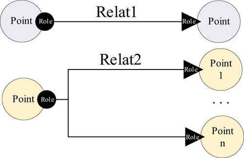
During the interaction of data between subsystems, two data flow patterns should be considered when the co-simulation scenario is automatically generated. (1) One inpoint connects to one outpoint; (2) one inpoint connects to multiple outpoints. Two definitions are established to describe these two patterns. The relationship is presented in Figure . and
refer to the former pattern and the latter pattern, respectively. Thus,
is described as formula (11).
(11)
(11)
Figure 4. The two data flow patterns during co-simulation.
The subclasses of belong to parameter information. The subclasses of
and the subclasses of
belong to architecture information used to integrate digital entities rapidly.
Object Properties
Definition 3:
Token refers to the first
. Every
has the corresponding domain and range. Token
refers to the collection of a
. A indicates a specific
; B represents the domains of the
; C denotes the ranges of the
. Thus, the first
, which is
, is described as
indicates that the graph includes object, role, and relationship.
(14)
(14)
indicates that each object has the property to execute co-simulation.
(15)
(15)
exhibits the relationship between object and point. The object performs interaction through point.
(16)
(16)
suggests that the role represents the data flow direction. The role sticks to the point.
(17)
(17)
is used to connect roles and relationships. The correctness of data flow direction is ensured by
.
(18)
(18)
(19)
(19)
and
indicate that the relationship between roles corresponds to the two types of
.
(20)
(20)
indicates
belong to
and
.
Data Properties
The Data Properties in the ontology are used to define the information type and the value type of a class itself. refers to the
in the owl file.
(21)
(21)
,
,
, and
represents the design information, life information, architecture information, and parameters information using in the co-simulation, respectively. Token
refers to the collection of a specific
. D indicates the specific
. E and its subclasses denote the domains of the
. F stands for the ranges of the
.
According to the four types of information, there are 4 attributes in , defined as:
(22)
(22)
indicates that
and
belong to the design information, and their value type is the string.
(23)
(23)
suggests the content of life information and its value type.
(24)
(24)
denotes the content of architecture information and its value type.
The has two sub-DP called
and
.
stores the value of the simulation result.
indicates the information type used for co-simulation. Token refers to the collection of the subclass of data property, the relationship between two data properties is described as formula (25).
(25)
(25)
(26)
(26)
reflects the content of parameter information and its value type.
shows the result of variables and their value type.
(27)
(27)
Design information indicates the designer's information and indicates the parties involved in the current simulation scenario to ensure the correctness of the current simulation scenario. Life information is used for version management of the co-simulation. It ensures the reuse of digital entities. When one of the digital entities is changed, the others do not need to be changed accordingly. It is available to build different simulation scenarios based on different model versions. Architecture information ensures the correct interoperability between heterogeneous digital entities during the co-simulation process. It includes both the direction of data exchange and the key information to establish a complete data channel between digital entities. Parameter information manages the running time and number of steps in the simulation to ensure the initialisation and instantiation of the co-simulation scenario. It ensures that the same co-simulation parameters are used during the co-simulation running.
Through the definition of ,
, and
, the four types of information are defined, and the knowledge for co-simulation is formed. The detailed concept of the attributes is described using the formula (1-27). The interconnection relationships between different digital entities are accurately described by instantiating the ontology model based on GOPPRR. The instantiated ontology establishes correct relationships between data produce digital entity and data consumer digital entity to guarantee the correct link. The unified ontology model is adopted to develop the cognition capability in CT for supporting the rapid integration of digital entities in co-simulation.
Compared to the FMU ontology used in the literature (Szulman et al. Citation2005), the FMU knowledge for co-simulation is taken as part of the unified ontology. The FMU knowledge is mainly used in the . As for a complex engineering system, the interconnection relationship is vital for the co-simulation process. The ontology established not only includes the information for the topology between digital entities but also includes the essential information for supporting the co-simulation process. The semantic representation in ontology uses a uniform form to prevent confusion in the description of the co-simulation scenarios. The co-simulation algorithm can also automatically operate the simulation solution through the ontology in CT architecture. Besides, the co-simulation results also can be stored as part of the knowledge in the ontology for result reasoning later.
4.2 Co-simulation
Co-simulation is to integrate the digital entities from different tools and establish communication between the heterogeneous interface. Moreover, an information base must be provided in the early phase of the simulation project (Rabe and Gocev Citation2012). CT is used to automatically accomplish the co-simulation of complex engineered systems. Engineers coding for co-simulation would be eliminated with the use of ontology in CT. Besides, the heterogeneous interface will be replaced by FMI.
Several works of literature have been developed the Master-Slave architecture based on FMI because the communication between the subsystems is not part of the FMI standard (Functional Mock-up Interface (FMI) Specification). Bastian et al. (Bastian et al. Citation2011) developed an advanced master-slave algorithm to fulfil co-simulation. They take master as an interface to exchange data between slaves. Broman et al. (Broman et al. Citation2013) designed deterministic master algorithms to orchestrated FMUs. The master algorithms execute the FMUs after configuring the FMUs state are the same. Cremona et al. (Cremona et al. Citation2016) used the deterministic master algorithm proposed by (Broman et al. Citation2013) to establish an integrated environment based on FMI. But they arranged the FMUs manually in a graphical user interface. On these bases, the master-slave algorithm proposed in CT is to control the data interaction between slaves. The master manage slaves to communicate with each other directly. Each slave executes after configuring the FMU state. The FMUs are implemented co-simulation in the same application code generated by CT architecture. Different digital entities only need to be packaged into FMUs according to the FMI standard and provided to CT for automatic simulation, without the need to manually write co-simulation code or operate in specific software. Thus, the co-simulation algorithm provides a unified simulation environment based on FMI. And the co-simulation process is executed automatically by CT.
A master-slave architecture is designed for the process of the co-simulation approach. The co-simulation master functions are implemented in one software. The data exchange between the sub-systems (slaves) is handled by the master only. The slaves directly communicate with each other. The FMI specification is taken as the implementation standard to build unified co-simulation environments. The co-simulation process of the co-simulation algorithm is presented in Figure . The ontology is presented on the left side. The workflow of the co-simulation progress is exhibited on the right side. Ontology provides the necessary knowledge to support the co-simulation process.
Figure 5. Ontology model and co-simulation algorithm.
Table
The co-simulation method consists of 4 stages. In the first stage, the master registers slaves when the simulation starts. The master controls each slave by slave ID () in ontology and configures the slave number in the current co-simulation scenario. In the second stage, the step size of every slave is unified. Then, the master initialises every slave and enters initialisation mode. Besides, the input value and output value of the slave are consistent with the initial value. In the third phase, the master configures the direct slave-to-slave data exchange. The map of the simulation data exchange topology is generated. And the slaves start to simulate. Each slave needs to set and acquire simulation results until the simulation time is reached. Finally, the master stops the scenario safely when the set simulation time has arrived. The detailed co-simulation process is described as follows.
The fmiSetReal/Integer/Boolean/String(S_i, …) is the function in FMI specification, and is used to set the value of the simulation parameters. The fmiGetReal() is applied to obtain the simulation results of slave i. The fmiDoStep(
) is employed to simulate slave i. The returned values are labelled with a simulation time consistent with others. The fmiFree(
) is adopted to safely finish the co-simulation.
The digital entities are integrated to finish the co-simulation by instantiating the above co-simulation algorithm. The co-simulation process not only considers the integration of digital entities but also controls the steps of each slave to guarantee the correctness of the simulation results. In the master-slave architecture, the simulation time step of slaves (digital entities) is controlled by master time tc. At the co-simulation stage, the master controls the slaves to simulate the next time step (tc + stepsize) when the simulation of the current step time (tc) is finished. In this way, the time synchronisation between slaves is guaranteed. Moreover, the problem of an ununified simulation environment is solved using the co-simulation algorithm based on FMI. Engineers have to instance the unified ontology model according to their complex engineered systems to execute co-simulation. There is no need to utilise different co-simulation methods to complete the co-simulation in the diverse simulation environment.
4.3 Result reasoning
The simulation results of multiple FMUs in one specific simulation scenario are usually stored in one data set, resulting in some obstacles to the extract and analysis of data. Since the digital entity creator usually names a variable with a simplified name, it is difficult for the non-related sub-system creator to comprehend several variables. Therefore, it is necessary to both obtain the simulation results and analyze the simulation result of a specific variable. The ontology can store the knowledge about the model variables and realise the correspondence and description of the simulation results. Thus, the reasoning capability in the CT is fulfilled by reasoning with ontology. The SPARQL is used to reason about simulation results, which are time-series data. SPARQL (SPARQL Protocol and RDF Query Language) is the standard language for querying RDF data (Pérez, Arenas, and Gutierrez Citation2009).
Reasoning based on the ontology and simulation results consists of 3 parts. 1) The of one point is automatically instanced according to the
and point name. Then the data are extracted to the corresponding variables according to the name of the FMUs ports. The value of one port is connected to the instantiated
by
. 2) The correctness of the entire simulation scenario is reasoned, revealing whether the sub-systems and quantities included in the simulation scene are correct and whether they are in line with the original engineer's assumptions. 3) CT reasons the point in the subsystem and the simulation result of the point at a specific simulation time.
Table
The content behind ‘?’ is the unknown quantity, namely, the knowledge to be reasoned. The developed CT utilises the co-simulation result and the knowledge in ontology to construct reasoning capability. There are some advantages of the reasoning capability in CT. First, CT reasons the simulation results. This function can be extended to reason a significant number of maintenance data and problem reports accrued by complex engineered systems. Second, CT reasons the relationships in complex systems. With the co-simulation results and ontology, it is useful for identifying unknown relations among them. Finally, CT reasons some specific information. This can be applied to discover recurring anomalies, causal, or similarity relations among reports, and trends indicating systemic problems. Additionally, the problems of lacking common structure, semantics, and indexing for engineers should also be addressed.
5. Evaluation using case study
In this section, the problem analysis of a gas turbine case for co-simulation is first introduced. Then, a specific implementation method of the CT is developed to construct the co-simulation scenario. Finally, the evaluation of CT is analysed with the motivation in section 2.
5.1 Problem analysis
Scenario Definition
A co-simulation scenario of a gas turbine is adopted to evaluate the approach of co-simulation enabled by CT. Given the main problems in the co-simulation of complex engineered systems, the co-simulation method in sections 3 and 4 is employed to integrate the heterogeneous digital entities of gas turbine sub-systems. The performance of a gas turbine under dynamic working conditions is analysed by the co-simulation scenario. A 300MW F-class gas turbine is selected, and the co-simulation is conducted under ISO operating conditions.
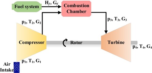
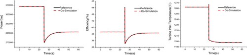
The gas turbine is a multi-disciplinary system, including air intake system, compressor, combustion chamber, rotor system, and turbine. In Figure , ambient air enters the compressor through the air intake system. Then, it is compressed into high-temperature and high-pressure gas. The exhaust of the compressor enters the combustion chamber and mixes with fuel in the combustion chamber to combust. The high-temperature gas of the turbine performs external work and is exhausted into the atmosphere. Therefore, the balance of mass conservation and the balance of flow conservation between various digital entities should be considered. Simultaneously, the characteristic maps of the compressor and turbine are required for solving the entire dynamic process. The dynamic characteristics of a gas turbine under different fuel flows are the basis for the control. Thus, it is necessary to simulate characteristics such as efficiency and outlet temperature when the fuel flow changes. The given fuel flow steps from 15.3 kg/s to 14 kg/s at t=25s by setting the simulation conditions. The CT finishes the co-simulation between these digital entities by providing a CT architecture, an ontology model, a co-simulation algorithm, and a reasoning algorithm.
Digital Entities of Gas Turbine Sub-Systems
Figure 6. Co-simulation scenario of the gas turbine.
In this section, the mathematical model of each sub-system in the gas turbine is introduced. The digital entities of the gas turbine case are established separately ascribed to their different functions. Every digital entity would be transformed into FMU for integration. The name of each digital entity corresponds to the sub-system's name in the ontology.
Digital entity of air intake system
The gas turbine uses air as the working medium, where its composition and temperature are crucial factors to ensure the performance and reliability of the gas turbine. The air intake system guarantees the operation performance of the gas turbine by adjusting the inlet air temperature. The air intake system is established to simulate the pressure loss of the intake system. In the gas turbine intake system, the input parameter is the mass flow of the air ; the output parameters are air sub-system
, outlet temperature
, and outlet pressure
. The pressure loss coefficient in the intake system is determined by formula (28).
(28)
(28) where
represents pressure loss,
denotes air density, and
refers to the loss coefficient.
Digital entity of compressor
The digital entity of the compressor is established using the working characteristic curve. According to formulas (29) and (30), the performance parameters of the compressor can be calculated, such as compressor efficiency and mass flow
.
(29)
(29)
(30)
(30) where
and
represent the specific performance evaluation functions depending on the working characteristic map;
denotes the outlet pressure of the compressor.
Digital entity of fuel system
The fuel system is responsible for providing the fuel required by the combustion chamber, and the dynamic change of the combustion is determined by the change of fuel mass flow. The fuel mass flow changes as the independent variable steps from 15.3 kg/s to 14 kg/s at t=25s. The enthalpy
of fuel is determined by the type of fuel it contains.
Digital entity of combustion chamber
The high-temperature and high-pressure gas from the compressor is fully mixed with the fuel provided by the fuel system and then enters the combustion chamber. The oxidation–reduction reaction of fuel is completed in the combustion chamber to further generate higher temperature gas with stronger workmanship. When the digital entity of the combustion chamber, the inlet enthalpy is equal to the outlet enthalpy of the compressor calculated according to the thermophysical properties. Considering the thermal inertia of the combustion chamber and the conservation of mass and energy, the differential formula for solving outlet enthalpy
can be obtained.
(31)
(31)
(32)
(32) where
and
denote fuel flow and fuel heating value, respectively;
and
indicate the outlet temperature and pressure of the combustion chamber, respectively;
is the gas density;
refers to the gas constant;
is the combustion chamber volume;
represents the heat dissipation;
and
are the total pressure loss coefficient and efficiency of the combustion chamber, respectively.
Digital entity of rotor system
The rotor of the gas turbine connects the compressor and the turbine. Thus, part of the output work of the turbine is used to compress air. The rotor speed can be obtained by calculating the overall power of the gas turbine.
(33)
(33) where
denotes the moment of inertia of the rotor;
and
represent the power of the turbine and compressor, respectively.
Digital entity of turbine
The high-temperature and high-pressure gas from the combustion chamber expand in the turbine to perform work, turning the heat energy of the gas into mechanical energy. The shaft power of the turbine drives the compressor and loads. The working characteristic curve of the turbine also includes flow characteristics and efficiency characteristics. Besides, the inlet temperature and pressure of the turbine are equal to the outlet temperature and pressure of the combustion chamber. The performance parameters of the turbine, such as turbine efficiency and mass flow
, can be calculated by equations (Equation34
(34)
(34) ) and (Equation35
(35)
(35) ).
(34)
(34)
(35)
(35) where
and
represent the specific performance evaluation functions depending on the working characteristic map. The 6 sub-systems of the Gas Turbine are integrated into a coupled model using the FMI-based co-simulation technology.
5.2 Cognitive twin supporting co-simulation
According to the proposed method, the CT of the gas turbine supporting co-simulation is realised. As illustrated in Figure , there are three sections of the implementation method: ontology modelling, code generation, and simulation section.
Figure 7. Implementation method of the Cognitive Twin.
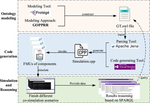
In Figure , first, the software Protégé is used to build the ontology model of the gas turbine. The building process is based on the GOPPRR method with the establishment of Object, OP, and DP of the ontology model. Then the OWL file is generated. In the code generation section, Apache Jena is used to parsing the ontology framework in Java. A link between owl file and data applications is formed, and programmes can be written in Java for development. Followed by the link, a c++ code template file for FMU simulation is defined according to the co-simulation algorithm in Visual Studio 2017. With the edition of the CPP file, the DP of each Object is read by Jena to generate the co-simulation code for the current ontology. Then, the DP and OP of ontology are adopted to complete the co-simulation. Finally, FMUs are invoked to integrate the co-simulation scenarios under various initial conditions. In the simulation and reasoning section, the system-level integrated digital entities are automatically executed in a unified co-simulation environment to predict the status of the life cycle, and the reasoning is realised with the SPARQL reasoning engine.
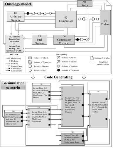
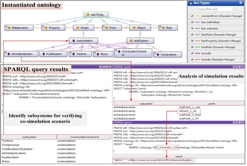
As revealed from Figure , the ontology model in CT for supporting the co-simulation of the gas turbine is established, and the progress is verified. According to the co-simulation scenario of the gas turbine, the ontology model includes the instances of Graph, Object, Property, Point, Role, and Relationship. Specifically, Graph indicates the entire co-simulation scenario. OWL: OP and OWL: Thing construct the ontology model of a specific complex system. There are six sub-systems in the ontology, and every sub-system has specific property. The connection between sub-systems contains two examples: 1) air intake system connecting to the compressor, and 2) combustion chamber connecting to compressor and turbine. These two examples are used to indicate the two types of . Through the co-simulation algorithm established before, the gas turbine co-simulation scenario is automatically generated, as illustrated at the bottom of Figure .
Figure 8. Co-simulation scenario generation with ontology.
5.3 Evaluation
The evaluation of CT refers to the evaluation of the cognitive capability when engineers implement the co-simulation by CT. The cognitive capability is evaluated from the aspects of co-simulation and reasoning. The co-simulation aspect includes:1) whether the formation quantity of the ontology in CT includes the four types of information to ensure subsequent co-simulation; 2) whether CT provides the necessary simulation environment for integration of multi-disciplinary models and executes co-simulation automatically. The simulation accuracy also should be ensured. The reasoning aspect includes: 1) whether the relationship in the co-simulation scenario can be inferred to verify the correctness of the entire co-simulation scenario; 2) whether CT can support the analysis of simulation result of a specific time point in digital entities. Therefore, the evaluation of CT is conducted separately from the above two aspects.
Co-simulation
For the GOPPRR modelling approach, Classes, OjectProperty, and DataProperty are combined to form a certain number of logical axiom and declaration axiom. The metric number in the ontology model constructed according to the unified modelling method are presented in Table .
Table 3. The metrics in the ontology of gas turbine case.
In the evaluation case, a total of 6 sub-systems are included, as well as 13 Relat1 relationships, 3 Relat2 relationships, 20 input points, and 17 output points. The data types in the simulation process include multiple data structures such as integer, double float, and float arrays. The co-simulation of the gas turbine is automatically performed by instantiating the unified ontology model. The simulation results are stored in the knowledge base and used in the subsequent reasoning process. At the end of the co-simulation evaluation, the accuracy of simulation results is analysed.
As indicated in Table , the difference between the results obtained by the CT-based simulation method and the reference value is relatively small. With the change in turbine inlet temperature as an example, the difference is less than 0.01%, which meets the simulation accuracy required by the gas turbine system. The simulation results indicate that the performance simulation model of the power system established by CT can effectively integrate the FMUs from different providers. Moreover, a unified co-simulation environment is successfully established to execute the co-simulation scenario. The efficiency of the integration is improved by automatically integrating distributed digital entities instead of manual integration. Through the implementation of CT, digital entities from different providers become accessible, and the integration effort can be significantly decreased. The work efficiency between designers and the reusability of the various information is expected to be improved.
Table 4. The simulation error between CT and reference value.
The dynamic operation process of the gas turbine is displayed in Figure . The reference data and co-simulation results are consistent. The effectiveness and flexibility of the approach are confirmed by the data comparison. The results are stored in a data set to provide reliable simulation data results for the next reasoning. Compared with the ontology-supported co-simulation approach in literature (Teixeira et al. Citation2020), literature (Elgharbawy et al. Citation2019), literature (Benjamin, Patki, and Mayer Citation2006), the co-simulation enabled by CT constructs the topological relationships between digital twins with a unified ontology modelling approach, which ensures the uniformity of knowledge representation in the simulation process. And the GOPPRR approach provides a sustainable mechanism for building different simulation scenarios. Moreover, compared with the literature (Benjamin, Patki, and Mayer Citation2006), the co-simulation method based on CT not only invokes the existing digital entities, but also enables to define different simulation scenarios by ontology, i.e. the initial values can be changed through the ontology. The master-slave co-simulation algorithm solves the challenge of the unified simulation environment and implements automatically in the architecture of CT, which significantly reduces the effort to configure co-simulation scenarios, integrate simulation models, and implement simulations.
Result reasoning:
Figure 9. Co-simulation results of the dynamic operation process of gas turbine.
In this section, the co-simulation result is transformed as formalised knowledge in the reasoning process with the instantiated Ontology. Firstly, the reasoning of CT makes simulation results correspond to each digital entity. Then, the correctness of the co-simulation scenario is verified using the CT expression and reasoning method. Next, the simulation results are analysed.
The reasoning results of the co-simulation scenario using the SPARQL are provided in Figure . The digital entities in the co-simulation are exhibited at the left bottom of Figure . It is demonstrated that the co-simulation scenario includes 6 sub-systems of the gas turbine; the reasoning result meets the co-simulation scenario of the gas turbine; the correctness of the entire co-simulation scenario is verified. The right bottom of Figure is to analyze the simulation results of one point when the simulation time is 60s. It is used to reason the points’ number and name of a digital entity and their co-simulation results. The process also can reason which subsystem a point belongs to.
Figure 10. Reasoning results of the CT.
The process of forming knowledge corresponds to the process of co-simulation, and the process of applying knowledge corresponds to the process of reasoning. The CT includes the capability to analyze simulation data. The overall concept includes collecting and transmitting data and analysing the collected data. The reasoning enabled by CT reduces the amount of calculation based on the simulation results. With the reasoning capability enabled by ontology, CT would be further extended to provide decision-making options based on the co-simulation results.
6. Limitation and future work
The cognitive twin is developed for supporting the co-simulation of complex engineered systems. And the purpose of co-simulation is to accomplish some specific objectives, such as fault diagnosis, status monitoring, and performance prediction. Thus, real-time data should be used in CT for accomplishing these different purposes. The CT has not yet considered using comparisons between real-time data and simulation data for fault diagnosis. Thus, the integration of real-time data and fault knowledge will be the subject of our future work.
Interaction of ontology with real-time data. As an extension of DT, CT will store the operation knowledge in the ontology to call real-time data and complete the interaction between real-time data and simulation data. It would receive feedback from the real-time data and automatically adds the corresponding operation knowledge of complex systems continuously.
Addition of fault diagnosis capability in CT. Diagnosis capability and decision-making capability are added to the existing co-simulation capability and reasoning capability of CT. The diagnosis capability is to perform fault diagnosis of complex systems using the comparison between real-time data and simulation data and the fault diagnosis module in the ontology. The decision capability is to provide decision-making options according to the fault diagnosis results.
7. Conclusion
In this paper, a novel CT for supporting the co-simulation of complex engineered systems is investigated. Firstly, a unified ontology modelling approach is established to support the unified knowledge expression of co-simulation. Then, the co-simulation capability and reasoning capability of CT are developed based on algorithms and ontology to automatically execute the co-simulation. Finally, the flexibility of the proposed method is evaluated using the gas turbine case. The CT also provides a foundation for the next decision-making. Some development has been made in solving the following problems:
The problem of the rapid integration of digital entities in co-simulation. Correct topologies between data producers and data consumers are established by the unified ontology modelling approach to guarantee the correct link. The rapid integration is supported by the four types of information in the ontology.
The problem of an ununified simulation environment. The information management, co-simulation, and analysis of complex engineered systems are achieved using the method proposed. Besides, the problem of a unified co-simulation environment is solved by the CT architecture developed based on a master-slave co-simulation algorithm with ontology and FMI.
Acknowledgments
This work is supported by the National Natural Science Foundation of China (Grant Nos. 51906138 and 51876116), Program of China Postdoctoral Science Foundation (grant number 2019M650085).
Disclosure statement
No potential conflict of interest was reported by the author(s).
Additional information
Funding
Notes on contributors

Yuanfu Li
Yuanfu Li, is a PhD student at the Institute of Turbomachinery, School of Mechanical Engineering, Shanghai Jiao Tong University. He received his bachelor's degree at SJTU as well. His research interest are co-simulation of complex engineering systems and health management.
Jinwei Chen
Jinwei Chen, is a research scientist at SJTU. He received his PhD at the School of Mechanical Engineering, Shanghai Jiao Tong University in 2018. His research interest is the combined cycle of Fuel Cell and Gas Turbine, application of MBSE in Gas Turbine, etc.
Zhenchao Hu
Zhenchao Hu, is a PhD student at Shanghai Jiao Tong University. He received his bachelor's degree at Wuhan University in Mechanical and Electronic Engineering. His research interest remain in data integration, prognostics health management, etc.
Huisheng Zhang
Zhang Huisheng, is a Professor at the Turbomachinery Institute, School of Mechanical Engineering in Shanghai Jiao Tong University. He is the editorial board member of the Journal of Computer Simulation, and invited reviewer for several journals such as Energy, Fuel Cells, and so on.

Jinzhi Lu
Jinzhi Lu*, CSEP, is a research scientist at EPFL. He received his PhD at KTH Royal Institute of Technology, Mechatronics Division in 2019. His research interest is MBSE tool-chain design. He is a senior member of the China Council on Systems Engineering (CCOSE).
Dimitris Kiritsis
Dimitris Kiritsis, is a Faculty Member with the Institute of Mechanical Engineering, School of Engineering, Ecole Polytechnique Fédérale de Lausanne (EPFL), Lausanne, Switzerland, where he is leading a research group on ICT for sustainable manufacturing. He also serves as the Director of the Doctoral programme of EPFL on Robotics, Control, and Intelligent Systems (EDRS).
Reference
- Awais, M. U., P. Palensky, W. Mueller, et al. 2013. “Distributed Hybrid Simulation Using the HLA and the Functional Mock-up Interface[C]//IECON 2013-39th Annual Conference of the IEEE Industrial Electronics Society.” IEEE 2013: 7564–7569.
- Bajaj, M., B. Cole, and D. Zwemer. 2016. “Architecture to Geometry-Integrating System Models with Mechanical Design[M].” AIAA SPACE 2016: 1–19.
- Bao, Q., G. Zhao, Y. Yu, et al. 2020. “Ontology-based Modeling of Part Digital Twin Oriented to Assembly[J].” Proceedings of the Institution of Mechanical Engineers,Part B: Journal of Engineering Manufacture Epub ahead of print 20 July 2020 : 1–13.
- Bastian, J., C. Clauß, S. Wolf, et al. 2011. “Master for Co-Simulation using FMI.” Proceedings of the 8th International Modelica Conference; March 20th-22nd; Technical Univeristy; Dresden; Germany. Linköping University Electronic Press, 63: 115–120.
- Benjamin, P., M. Patki, and R. Mayer. 2006. “Using Ontologies for Simulation Modeling.” Proceedings of the 2006 Winter Simulation Conference. IEEE, 1151–1159.
- Bohács, G., and A. Rinkács. 2017. “Development of an Ontology-Driven, Component Based Framework for the Implementation of Adaptiveness in a Jellyfish-Type Simulation Model[J].” Journal Of Ambient Intelligence And Smart Environments 9 (3): 361–374.
- Boussuge, F., C. M. Tierney, H. Vilmart, et al. 2019. “Capturing Simulation Intent in an Ontology: CAD and CAE Integration Application[J].” Journal of Engineering Design 30 (10-12): 688–725.
- Brandt, S. C., J. Morbach, M. Miatidis, M. Theissen, M. Jarke, and W. Marquardt. 2006. “Ontology-Based Information Management in Design Processes.” 9th Int. Symp. Process Systems Engineering, Garmisch-Partenkirchen, Germany.
- Broman, D., C. Brooks, L. Greenberg, et al. 2013. “Determinate Composition of FMUs for Co-Simulation.” 2013 Proceedings of the International Conference on Embedded Software (EMSOFT). IEEE, 1-12.
- Cameron, B., E. Crawley, and D. Selva. 2016. “Systems Architecture. Strategy and Product Development for Complex Systems.” Pearson Education.
- Chen, J., T. Cai, W. He, et al. 2020. “A Blockchain-Driven Supply Chain Finance Application for Auto Retail Industry.” Entropy 22 (1): 95.
- Chen, Z., S. Guo, J. Wang, et al. 2019. “Toward FPGA Security in IoT: a new Detection Technique for Hardware Trojans.” IEEE Internet of Things Journal 6 (4): 7061–7068.
- Chira, O., C. Chira, T. Roche, et al. 2006. “An Agent-Based Approach to Knowledge Management in Distributed Design[J].” Journal of Intelligent Manufacturing 17 (6): 737–750.
- Cremona, F., M. Lohstroh, S. Tripakis, et al. 2016. “FIDE: An FMI Integrated Development Environment.” Proceedings of the 31st annual ACM Symposium on Applied Computing, 1759–1766.
- Elgharbawy, M., A. Schwarzhaupt, M. Frey, et al. 2019. “Ontology-based Adaptive Testing for Automated Driving Functions Using Data Mining Techniques[J].” Transportation Research Part F: Traffic Psychology and Behaviour 66: 234–251.
- Elhdad, R., N. Chilamkurti, and T. Torabi. 2013. “An Ontology-Based Framework for Process Monitoring and Maintenance in Petroleum Plant[J].” Journal of Loss Prevention in the Process Industries 26 (1): 104–116.
- Fatfouta, N., and S. Le-Cardinal J. 2021. “An Ontology-Based Knowledge Management Approach Supporting Simulation-Aided Design for car Crash Simulation in the Development Phase[J].” Computers in Industry 125: 103344.
- Functional Mock-up Interface (FMI) Specification. http://fmi-standard.org/.
- Grieves, M. W. 2003. “PLM-Beyond Lean Manufacturing.”
- Hemingway, G., H. Neema, H. Nine, et al. 2012. “Rapid Synthesis of High-Level Architecture-Based Heterogeneous Simulation: a Model-Based Integration Approach[J].” Simulation 88 (2): 217–232.
- HLA Working Group. 2000. “IEEE Standard for Modeling and Simulation (M&S) High Level Architecture (HLA)-Framework and Rules.” IEEE Standard, 10.
- Karhela, T., A. Villberg, and H. Niemistö. 2012. “Open Ontology-Based Integration Platform for Modeling and Simulation in Engineering.” International Journal of Modeling, Simulation, and Scientific Computing 3 (02): 1250004.
- Kelly, S., and J.-P. Tolvanen. 2008. Domain-Specific Modeling. Hoboken, NJ, USA: John Wiley & Sons,Inc.
- Kharlamov, E., F. Martin-Recuerda, B. Perry, et al. 2018. “Towards Semantically Enhanced Digital Twins.” 2018 IEEE International Conference on Big Data (Big Data). IEEE, 4189-4193.
- Li, Y., J. Tao, and F. Wotawa. 2020. “Ontology-based Test Generation for Automated and Autonomous Driving Functions[J].” Information and Software Technology 117: 106200.
- Lu, J., D. Chen, G. Wang, et al. 2021. “Model-Based Systems Engineering Tool-Chain for Automated Parameter Value Selection.” IEEE Transactions on Systems, Man, and Cybernetics: Systems IEEE 2021: 1–15.
- Lu, Jinzhi, and Xinguo Wang. 2019. “Martin Törngren Design Ontology in a Case Study for Co-Simulation in a Model-Based Systems Engineering Tool-Chain[J].” IEEE Systems Journal, 2911418.
- Lu, J., X. Zheng, A. Gharaei, et al. 2020. “Cognitive Twins for Supporting Decision-Makings of Internet of Things Systems.” Proceedings of 5th International Conference on the Industry 4.0 Model for Advanced Manufacturing. Springer, Cham, 105–115.
- Magargle, R., L. Johnson, P. Mandloi, et al. 2017. “A Simulation-Based Digital Twin for Model-Driven Health Monitoring and Predictive Maintenance of an Automotive Braking System.” Proceedings of the 12th International Modelica Conference, Prague, Czech Republic, May 15-17, 2017. Linköping University Electronic Press, 132: 35–46.
- Millwater, H., J. Ocampo, and N. Crosby. 2019. “Probabilistic Methods for Risk Assessment of Airframe Digital Twin Structures[J].” Engineering Fracture Mechanics 221: 106674.
- Neema, H., J. Gohl, Z. Lattmann, et al. 2014. “Model-Based Integration Platform for FMI Co-Simulation and Heterogeneous Simulations of Cyber-Physical Systems.” Proceedings of the 10 th International Modelica Conference; March 10-12; 2014; Lund; Sweden. Linköping University Electronic Press, 096: 235–245.
- Nordahl, H., M. Rindarøy, S. Skjong, et al. 2020. “An Ontology-Based Approach for Simplified FMU Variable Connections With Automatic Verification of Semantically Correct Configuration[C].” International Conference on Offshore Mechanics and Arctic Engineering. American Society of Mechanical Engineers 84379: V06AT06A022.
- Nouidui, T. S., J. Coignard, C. Gehbauer, et al. 2019. “CyDER–an FMI-Based co-Simulation Platform for Distributed Energy Resources[J].” Journal of Building Performance Simulation 12 (5): 566–579.
- Pérez, J., M. Arenas, and C. Gutierrez. 2009. “Semantics and Complexity of SPARQL.” ACM Transactions on Database Systems (TODS) 34 (3): 1–45.
- Peshev, D., and A. G. Livingston. 2013. “OSN Designer, a Tool for Predicting Organic Solvent Nanofiltration Technology Performance Using Aspen One, MATLAB and CAPE OPEN[J].” Chemical Engineering Science 104: 975–987.
- Psarommatis, F. 2021. “A Generic Methodology and a Digital Twin for Zero Defect Manufacturing (ZDM) Performance Mapping Towards Design for ZDM.” Journal of Manufacturing Systems 59: 507–521.
- Rabe, M., and P. Gocev. 2012. “Applying Semantic Web Technologies for Efficient Preparation of Simulation Studies in Manufacturing.” Proceedings of the 2012 Winter Simulation Conference (WSC). IEEE, 1-12.
- Rasheed, A., O. San, and T. Kvamsdal. 2019. “Digital Twin: Values, Challenges and Enablers.” arXiv preprint arXiv:1910.01719.
- Rind, D. 1999. “Complexity and Climate.” Science 284 (5411): 105–107.
- Ríos, J., F. M. Morate, M. Oliva, et al. 2016. “Framework to Support the Aircraft Digital Counterpart Concept with an Industrial Design View[J].” International Journal of Agile Systems and Management 9 (3): 212–231.
- Schwarz, J. S., R. Elshinawy, R. P. R. Acosta, et al. 2019. “Ontological Integration of Semantics and Domain Knowledge in Hardware and Software Co-simulation of the Smart Grid.” International Joint Conference on Knowledge Discovery, Knowledge Engineering, and Knowledge Management. Springer, Cham, 283–301.
- Schwarz, J. S., C. Steinbrink, and S. Lehnhoff. 2019. “Towards an Assisted Simulation Planning for co-Simulation of Cyber-Physical Energy Systems.” 2019 7th Workshop on Modeling and Simulation of Cyber-Physical Energy Systems (MSCPES), IEEE, 1–6.
- Seshadri, B. R., and T. Krishnamurthy. 2017. Structural Health Management of Damaged Aircraft Structures Using Digital Twin Concept.” 25th aiaa/ahs adaptive structures conference, 1675.
- Shafto, M., M. Conroy, R. Doyle, et al. 2012. “Modeling, Simulation, Information Technology & Processing Roadmap[J].” National Aeronautics and Space Administration 32 (2012): 1–38.
- Szulman, P., M. Hefke, A. Trifu, et al. 2005. “Using Ontology-Based Reference Models in Digital Production Engineering Integration[J].” IFAC Proceedings Volumes 38 (1): 206–211.
- Teixeira, B., G. Santos, T. Pinto, et al. 2020. “Application Ontology for Multi-Agent and Web-Services’ Co-Simulation in Power and Energy Systems[J].” IEEE Access 8: 81129–81141.
- Tu, Zhiying, G. Zacharewicz, and D. Chen. “Developing a Web-Enabled HLA Federate Based on poRTIco RTI.” Proceedings of the 2011 Winter Simulation Conference (WSC), 2011, pp. 2289–2301.
- Tuegel, E. 2012. “The Airframe Digital Twin: Some Challenges to Realization.” 53rd AIAA/ASME/ASCE/AHS/ASC Structures, Structural Dynamics and Materials Conference 20th AIAA/ASME/AHS Adaptive Structures Conference 14th AIAA. 1812.
- Verstichel, S., F. Ongenae, L. Loeve, et al. 2011. “Efficient Data Integration in the Railway Domain Through an Ontology-Based Methodology[J].” Transportation Research Part C: Emerging Technologies 19 (4): 617–643.
- Wei, Y., R. Wang, Y. Hu, et al. 2012. “From web Resources to Agricultural Ontology: a Method for Semi-Automatic Construction[J].” Journal of Integrative Agriculture 11 (5): 775–783.