ABSTRACT
Understanding the dynamic free surface of geophysical flows has the potential to enable direct inference of the flow properties based on measurements of the free surface. An important step is to understand the inherent response of free surfaces in depth-limited flows. Here a model is presented to demonstrate that free surface oscillatory spatial correlation patterns result from individual surface features oscillating vertically as they advect over space and time. Comparison with laboratory observations shows that these oscillating surface features can be unambiguously explained by simple harmonic motion, whereby the oscillation frequency is controlled by the root-mean-square water surface fluctuation, and to a lesser extent the surface tension. This demonstrates that the observed “complex” wave pattern can be simply described as an ensemble of spatially and temporally distributed oscillons. Similarities between the oscillon frequency and estimated frequency of near-bed bursting events suggest that oscillon behaviour is linked with the creation of coherent flow structures.
1 Introduction
The water surface behaviour of depth-limited turbulent open channel flows is not yet fully understood. No direct quantified link has been shown between the free surface behaviour and the underlying hydraulic processes in such flows, and this is believed to be due to the convoluted nature of dynamic flow surfaces. Understanding the mechanisms behind the apparently random nature of free surface fluctuations could unlock the potential to predict the free surface pattern for a given flow condition. Furthermore, the understanding of free surface dynamics may enable non-intrusive characterization of flow conditions and hydraulic energy losses based solely on measured free surface behaviour (Fujita, Furutani, & Okanishi, Citation2011; Horoshenkov, Nichols, Tait, & Maximov, Citation2013; Johnson & Cowen, Citation2014).
It is believed that rough water surface features may be formed by several processes. Depth scale turbulent flow structures in hydraulically rough, free surface flows have been observed by a number of researchers (e.g. Best & Kostaschuk, Citation2002; Shvidchenko & Pender, Citation2001), and have been shown to affect the free surface pattern (Fujita et al., Citation2011; Savelsberg & van de Water, Citation2009). Fujita et al. (Citation2011) showed that boils on the free surface of a uniform turbulent flow correlated with rising horizontally oriented structures. Tamburrino and Gulliver (Citation2007) used surface particle tracking velocimetry to show in a moving bed flume that areas of upwelling on the free surface corresponded to areas of vorticity, and postulated that the free surface pattern is a manifestation of the turbulent structures existing throughout the depth of flow. Savelsberg and van de Water (Citation2009) used particle image velocimetry (PIV) in a horizontal plane just below the free surface of a 0.31 m deep turbulent shallow flow to show that free surface indentations correlated with sub-surface vertical eddies shed from a vertical cylinder. For a homogeneous isotropic turbulence field they concluded that the effect of turbulent structures on the free surface is overwhelmed by random capillary gravity waves that propagate away from turbulent disturbances. However, Guo and Shen (Citation2010) modelled similar flows using DNS (direct numerical simulation), and found that only 2.2–12.1% of the potential energy of the surface was associated with propagating waves, suggesting that the majority of the surface structure is governed by the gravity driven response of the free surface to the turbulence induced roughness. The spatial domain examined by Savelsberg and van de Water (Citation2009) was much smaller than the length scales of typical depth scale features reported for these kinds of flows. It is possible that at the small scale examined by Savelsberg and van de Water (Citation2009) capillary gravity waves dominate, but that in a larger field of view the water surface features caused by depth scale flow structures dominate the free surface pattern as suggested by Guo and Shen (Citation2010).
What was not studied by Savelsberg and van de Water (Citation2009) or Guo and Shen (Citation2010) is the spatial and temporal evolution of the free surface disturbances. The concept of gravity waves being generated outward seems intuitively sensible, as any disturbance to a water surface is likely to generate secondary ripples. However, since gravity waves are essentially described as a one-dimensional process involving plane waves, they only apply to the far field for circular wave fronts, not the near-field location of the generating disturbance. The near-field issue is avoided by Savelsberg and van de Water (Citation2009) by describing the near-field region as a Gaussian disturbance; however it is not clear what happens to this disturbance after its initial inception. Their qualitative descriptions suggest that surface features are relatively persistent, as found by other studies (Guo & Shen, Citation2010; Nezu & Nakagawa, Citation1993), but their analytical model includes a time dependent cosine term that would cause the initial surface feature to fluctuate up and down over time. This raises the question of whether surface dimples truly represent sub-surface vortices, or whether these vortices are forming some kind of oscillatory motion, dimples and boils. This would agree with the oscillatory spatial correlation functions presented by Horoshenkov et al. (Citation2013), and with other relevant models, such as classical tsunami theory (Ward & Asphaug, Citation2000) which suggests that a patch of water struck by an object will oscillate up and down over time.
The key ambiguity in present understanding is the response of the free surface at the point of a disturbance. Where this disturbance is likely caused by a turbulent structure, does the free surface simply display a boil or dimple until the turbulent structure dissipates? Does the surface respond as though it were struck by an object, fluctuating up and down? What happens when the dynamically rough, free surface is struck by a number of turbulence structures distributed statistically in time and space? These questions need to be answered to understand the dynamic response of the free surface to structure impingement as this may well contribute significantly to the apparent dynamic nature of turbulent free surfaces.
The aim of this study is to better understand the oscillatory nature of the free surface spatial correlation functions observed by Horoshenkov et al. (Citation2013), by developing a model to provide a physically plausible explanation of the way in which free surfaces respond to disturbances.
2 A conceptual model for the behaviour of the free surface
In this section a conceptual model will be proposed that mechanistically explains the observed dynamic response of the free surface of turbulent free surface flows. The model will then be evaluated in section 3 using detailed experimental data of a moving water surface.
2.1 The theory
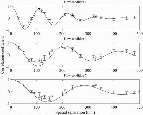
When the free surface of a turbulent flow is disturbed, the response of the free surface over time and space is currently not well understood. A theory is proposed here that attempts to describe the dynamic nature of such free surfaces. Horoshenkov et al. (Citation2013) proposed a spatial correlation function of the temporal water surface elevation in the frame of the stationary observer. This correlation function represents the evolution of the free surface pattern as it advects over space and time, and was characterized for flows with depth from 40 to 100 mm and Froude number from 0.31 to 0.75. An example of this spatial correlation function is given in Fig. for three arbitrary measured flow conditions. The data points represent the extremum value of the temporal cross correlation of free surface fluctuations measured at two separated locations. The error bars represent the variation between three repeated experiments for each flow condition. The solid lines represent the best fit of the expression given in Eq. (1).
Figure 1 The streamwise spatial correlation function of the free surface elevation (Horoshenkov et al., Citation2013) for three steady flows with uniform average water depths: 40, 70 and 100 mm. Markers represent measured data; error bars show variation between three repeated measurements; solid line shows best fit according to Eq. (1)
Horoshenkov et al. (Citation2013) showed that this spatial behaviour can be described by the following expression:
(1)
where
is the spatial lag,
is the spatial radius of correlation, and the value of
is the characteristic spatial period of the water surface roughness pattern. While this expression describes the overall evolution of the surface pattern, it does not provide an explanation for the observations in terms of individual surface features. The functions shown in Fig. could equally well be represented as temporal correlations of spatial data in the frame of an observer travelling with the surface flow, by dividing the spatial separation with the surface flow velocity. In this case, it can be noted that the functions could resemble an underdamped simple harmonic motion. This pattern would suggest that the surface roughness pattern inverts periodically over time, as it advects at the surface flow velocity, giving rise to a new definition of the characteristic spatial period:
(2)
where
is the free surface advection velocity, and
is the temporal frequency of oscillation of the free surface features. The periodic vertical oscillation of the free surface pattern can also be seen to some degree in the wave probe data reported by Horoshenkov et al. (Citation2013). It is hypothesized that once formed, each of these initial disturbances advects at the surface flow velocity and oscillates about the mean surface level as the forces of gravity and surface tension attempt to regain equilibrium. It is proposed here that an oscillating surface feature, which may be instigated by a turbulent structure, behaves according to well-accepted mechanical laws and can also generate gravity waves which then propagate in all directions. The concept of an oscillating individual free surface feature is new in the context of turbulence generated water surface roughness, but has been observed in other applications such as vibrating granular media (Eggers & Riecke, Citation1999; Rothman, Citation1998) and vertically vibrated pools of fluid (Shats, Xia, & Punzmann, Citation2012). Umbanhowar, Melo, and Swinney (Citation1996) were the first to term waves of this type oscillons (oscillating solitons).
For most real flows, there are multiple turbulent structures formed in the flow (Buffin-Bélanger, Roy, & Kirkbride, Citation2000; Fujita et al., Citation2011; Roy, Buffin-Bélanger, Lamarre, & Kirkbride, Citation2004), and hence this new theory would expect there to be multiple oscillons formed on the free surface of a turbulent flow at different points in space. These discrete oscillating features may well overlap, and since they may also appear at different times, they may well be out of phase with one another. It was suspected that this structure gives rise to the very complex surface patterns that are observed by eye, but that this complex behaviour may be simply explained by a number of oscillons that overlap in space and time and respond according to well accepted mechanical laws.
2.2 The model
First, a single upward free surface deformation (boil) is considered. Due to the weight of water lifted, and the component of surface tension acting downwards, a net downward force is present. Conveniently, if the system is released and the inertia causes the upward boil to become a downward dimple, the upward force is also a function of the weight of water displaced and the upward component of the surface tension. The magnitude of this force sensibly increases as the mean height (or depth) of the free surface deformation increases. In this sense the system is analogous to a spring and mass system, whereby the gravitational and surface tension forces act as a spring moving a mass of water up and down. The problem is thereby similar to an oscillating buoyant body, not unlike the half immersed circular cylinder described by Ursell (Citation1949).
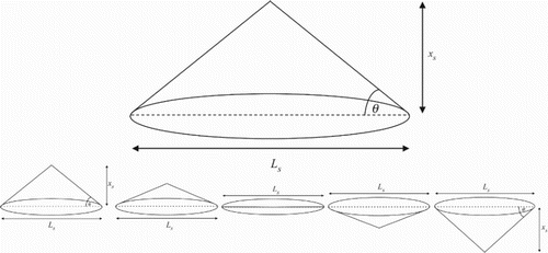
considers an instantaneous surface boil as an idealized cone. Here is the surface deformation height,
is the horizontal length of the turbulent structure generating the surface feature, and
is the tangent of the idealized angle at which surface tension is applied. The net downward force is given by the weight of the cone and the vertical component of surface tension around the circumference of the cone’s base:
(3)
where
is the density of the fluid,
is the acceleration due to gravity, and
is the surface tension force per metre. It can be shown that for small angles (below around 10°),
, allowing Eq. (3) to be simplified to:
(4)
Figure 2 Idealized free surface deformation, and a half period of the conceptualized oscillation of the surface deformation (omitting decay)
From standard spring theory, the spring stiffness is defined as the force exerted per unit of deflection. In this case the stiffness of the system can be defined as:
(5)
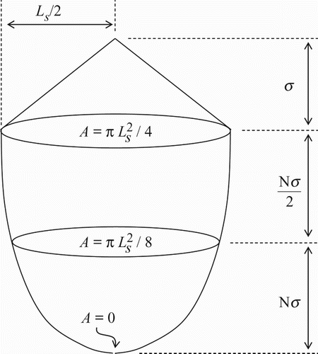
The mass of the spring-mass system is now considered. The virtual mass concept introduced by Ursell (Citation1949) showed that an oscillating body “carried” with it a mass of water, adding to its effective mass. In the context of water surface oscillons, this additional mass can be considered as the quantity of water affected by the motion of the oscillon. The depth of influence of a given oscillon is expected to be proportional to its vertical amplitude. Hence, the depth of influence can be defined as
, where
is the number of root-mean-square (RMS) water surface wave heights, termed the depth of influence factor, and
is the RMS wave height. As a first approximation, a circular zone of influence is considered whose area decreases linearly from
at the free surface to
at
wave heights below the free surface. The volume of water in this zone of influence is equal to that of a cylinder of diameter
and height
. This zone is illustrated schematically in Fig. , and as such the total mass of the system including the cone shaped boil is given by:
(6)
Figure 3 Schematic diagram of the effective volume of water influenced by the surface feature oscillation
The frequency of simple harmonic motion can be calculated by:
(7)
and substituting in Eqs (5) and (6) this gives:
(8)
For water at room temperature, the surface tension is small ( N m−1), and fluid density is large (
kg m−3), so that the second term becomes negligible provided
is sufficiently large. The error caused by neglecting the second term is below 8% for
m, below 1% for
m and below 0.1% for
m. In realistic flows the free surface features scale with the coherent flow structures (Savelsberg & van de Water, Citation2009), which in turn are observed to scale with the flow depth (Roy et al., Citation2004), so it is believed that this simplification can be used for flows with depth in the order of centimetres or greater. Neglecting the surface tension term allows the frequency of oscillation to be expressed solely as a function of the deformation height and the depth of influence factor:
(9)
presents the estimated oscillon frequency as a function of RMS wave height for a range of depth of influence factors, . The sensible range of
was estimated as follows. The thickness of the near-surface layer influenced by the dynamic surface is approximately equal to the turbulence integral length scale (Dabiri, Citation2003; Walker, Leighton, & Garza-Rios, Citation1996). Savelsberg and van de Water (Citation2009) examined flows similar to those considered here, and showed the ratio of turbulence length scale to flow depth to be approximately 0.1 to 0.26. The ratio of RMS wave height to flow depth is typically around 0.004 to 0.01 for the type of flows examined here (Horoshenkov et al., Citation2013). Hence, since
is the ratio of depth of influence to the RMS wave height, a combination of the two aforementioned ratios allows the realistic range of
to be estimated as
. Therefore,
is shown over this range in Fig. .
Figure 4 The estimated oscillon frequency as a function of the RMS wave height, , and depth of influence factor,
AAA
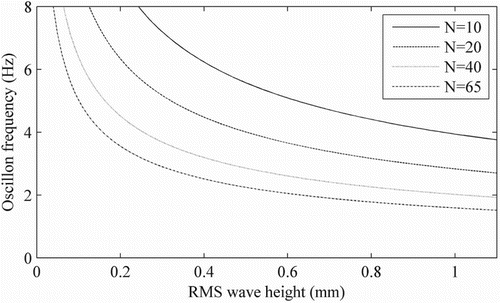
The shape of the curves in Fig. carries a clear physical sense: (i) as the depth of influence factor increases, the mass of water increases and so the oscillon frequency decreases; (ii) as the water surface roughness height tends toward zero, the mass of water being acted upon also tends toward zero, so the frequency of oscillation tends toward infinity; (iii) as the roughness height tends toward infinity, so too does the mass of affected water, meaning the frequency tends toward zero. The model is theoretically applicable to any water surface where an area of the surface is displaced vertically and then allowed to return to equilibrium under gravity, though there may be instances where the oscillon effect is overwhelmed by other processes such as travelling gravity waves. The result shown in Fig. will be tested in section 3 against experimental data.
3 Experiments
An experimental investigation was conducted to provide water surface elevation data to validate the proposed oscillon model. Two measurement techniques were employed to measure the free surface behaviour: high spatial-resolution visualization obtained via laser induced fluorescence; and data from seven conductive wave probes (each with high vertical and temporal accuracy, but deployed in a horizontally sparse array so as to obtain water surface data over larger streamwise distances).
Water surface data were recorded for a range of steady, uniform flows corresponding to the same flow conditions examined by Horoshenkov et al. (Citation2013). These flows were established in a 12.6 m long, 0.46 m wide, sloping rectangular flume (Fig. ) that contained a flat, static sediment deposit of uniform thickness. In these experiments, the flume gradient was varied from = 0.001 to 0.004. The uniform flow depth,
, and the depth-averaged mean flow velocity,
, were varied respectively from 40 to 100 mm and from 0.41 to 0.74 m s−1 via a flow control valve and an adjustable downstream weir (see Fig. ). The mean grain size of the bed gravel was
= 4.4 mm, which resulted in relative submergences ranging from
= 9 to 23. Reynolds number was defined as
, where
is the kinematic viscosity, and ranged from
= 17,000 to 67,000. Froude number was defined as
, and ranged from
= 0.31 to 0.75. Details of all the flow conditions are listed in .
Figure 5 Flume overview (adapted from Horoshenkov, Citation2013).
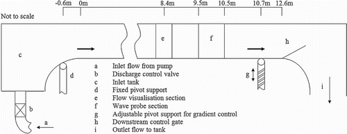
Table 1 Measured hydraulic conditions for gravel bed flows
The conductance wave probes were calibrated and sampled at 100 Hz, and were organized in a streamwise array along the centreline of the flume, at different lags, with the array covering a distance of 0.48 m. The array started at 9.5 m from the flume inlet. In this manner water surface data were collected and the RMS wave height was obtained at each probe location along the length of the array. The RMS from the individual probes varied from the mean by less than 10%. These measurement techniques are described in more detail by Horoshenkov et al. (Citation2013).
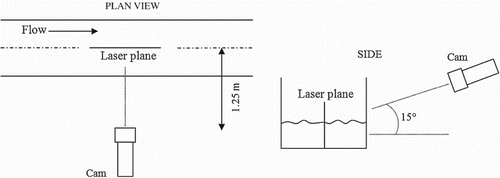
A laser induced fluorescence (LIF) technique was employed to measure the free surface deformation along a 200 mm streamwise length at the visualization section located at 8.4 m from the flume inlet as shown in Fig. . A diagram of the equipment arrangement for flow surface visualizations is shown in Fig. . The vertical laser sheet illuminated a volume approximately 220 mm long in the streamwise direction and approximately 3 mm thick in the lateral direction. The LIF camera, with an image area of 1600 × 600 pixels, was focused on the laser sheet, and was synchronized with the laser pulses, recording images at a frequency of 26.9 Hz. It was calibrated in air using a standard calibration grid, and was installed at an elevated position, looking down towards the water surface at an angle of 15° as shown in Fig. . The LIF set-up allowed for a clear line-of-sight between the surface profile and the camera. The camera was used to capture the position of the air–water interface and rhodamine WT dye was added to the flow in order to better define the free surface in the images. When illuminated with 532 nm laser light, the rhodamine was excited, emitting light at around 595 nm. A high-pass filter lens with a cut-off wavelength of 545 nm was used to discard the green (532 nm) light, but allow through the red (595 nm) light emitted by the rhodamine in the water. Once established, each flow condition was recorded on camera continuously for a duration of five minutes. Each instantaneous LIF image was binarized, and a 5 × 5 two-dimensional median filter was applied to remove spurious points of brightness. The free surface profile was then determined by detecting the threshold between the illuminated flow and non-illuminated air in each column of pixels. The calibration was used to convert from pixels into mm, giving a horizontal and vertical resolution of 0.15 mm. This process was applied to each of the 8070 images acquired for each of the 16 flow conditions examined. For each condition this resulted in a time series of surface profile, allowing the examination of surface behaviour over time and space with a known spatial and temporal resolution.
In this work, the conductance wave probe data were used to determine the mean statistical properties of the flow surface (RMS wave height) due to it representing the average of a larger spatial region, and being sampled at a higher frequency, while the LIF data were used to visualize surface behaviour due to its high spatial resolution. The characteristic period of the surface pattern was calculated using a cross-correlation technique that presents the extremum of the temporal cross-correlation as a function of probe separation (see Fig. ), and optimizes the variables in Eq. (1) according to a least-mean-squares algorithm.
The surface flow velocity was calculated by timing the transit of a floating tracer (150 µm Plascoat Talisman 30 powder, Plascoat Systems Limited, Farnham, UK) over a distance of 5 m. Each measurement was repeated three times for each flow condition and the mean surface velocity found to be accurate to within 3.7%.
4 Results and discussion
4.1 Oscillon theory validation
In order to validate the oscillon theory, one must examine the behaviour of the free surface features not only over time, but also over space. Here the LIF data will be used to visualize the motion of surface features, due to the high spatial resolution of this system.
Space–time (ST) velocity matrices allow the visualization of the relationship between simultaneous measurements taken at different points in a flow from relatively few sensors with sparse spatial distribution (Buffin-Bélanger et al., Citation2000; Roy et al., Citation2004). They have been used to depict graphically the evolution and advection of turbulent flow features in space and time by Roy et al. (Citation2004). The ST matrix technique will be used here to provide a qualitative assessment of the behaviour of dominant features in the free surface pattern as they advect with time through the measurement frame. In the present study, the time series of free surface elevation at each point was standardized by removing the time-averaged component, and normalizing the fluctuations by the standard deviation at that point. The resulting quantity is termed the normalized deviate, i.e.:
(10)
where
is the streamwise location and
is the instantaneous surface elevation fluctuation at location i, defined by:
(11)
where
is the instantaneous water depth. The standardized data allow visual assessment of the behaviour of the dominant water surface features. shows the space time matrices of the instantaneous water surface elevation for flow conditions 1, 3, and 6. These three conditions represent the full range of surface structures observed, and are characteristic of all the flow conditions examined. Here the greyscale corresponds to the value of the normalized deviate,
, from Eq. (10), which has units of number of standard deviations. An interesting phenomenon can be observed here: rather than showing clear striations where features are persistent over space and time, as is generally expected for sub-surface velocity data (Nikora & Goring, Citation2000a; Roy et al., Citation2004; Taylor, Citation1938), these plots exhibit trains of features fluctuating between high and low elevations over space and time.
Figure 7 A series of oscillatory free surface features that were observed advecting over space and time for flow conditions 1, 3, and 6. The white dashed lines indicate the surface velocity measured by the transit of a floating tracer
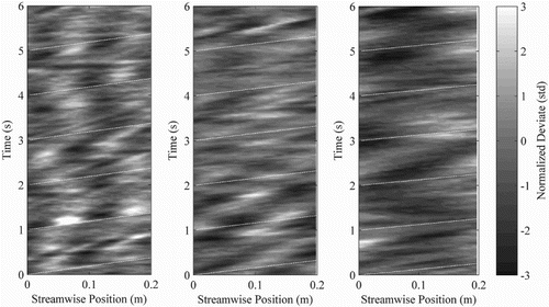
This observation would appear to qualitatively support the oscillon theory, and was observed in all the flow conditions described here. The spatial periods shown in Fig. match well with the characteristic spatial periods measured by conductive wave probe for the same flow conditions by Horoshenkov et al. (Citation2013). These series of areas of positive and negative elevations can be clearly observed in the case of flow condition 1, where the spatial period of the oscillatory features allows several periods to be observed in the spatial measurement frame. For flow condition 3 fewer periods of oscillation were captured, and by flow condition 6 it can be seen that the image frame only captured around half a period of oscillation. With knowledge of this oscillatory behaviour, similar patterns can in fact be observed in the free surface data of Fujita et al. (Citation2011). It also confirms the results of Savelsberg and van de Water (Citation2009) who suggested that the free surface exhibits a dynamic response of its own when disturbed by a turbulent flow structure. For the first time, this dynamic response can be identified as oscillon behaviour.
The ST matrices also make it possible to visually assess the trajectory of the oscillatory events over space and time. The gradient of these trajectories indicates the advection velocities of the oscillons. The slope of the white dashed lines in Fig. shows the surface velocity measured by the transit of a floating tracer. It can be seen that the oscillons are carried at a velocity close to that of the surface velocity.
The features of the free surface do not appear to be persistent in the same way as the sub-surface features that are thought to generate them (Guo & Shen, Citation2010; Yalin, Citation1992). The oscillatory trains of events in Fig. support the hypothesis that when impacted from below by a turbulent structure, the locality of the free surface responds by oscillating vertically over time as it advects over space. These data therefore suggest for the first time that oscillons exist in the dynamic free surface of shallow flows and that their properties may relate to those of the sub-surface turbulent structures. Oscillon behaviour is observed in all the flow surfaces examined in this study. The following section will examine the behaviour quantitatively.
4.2 Model validation
To validate the simple harmonic motion model, the frequency of free surface oscillation was calculated from the experimental data using Eq. (2) and from the simple harmonic motion model using Eq. (9). Here the conductance probe data were used to determine the characteristic spatial period and RMS wave height due to its higher spatial and temporal accuracy, and due to its data being obtained and averaged over a long streamwise distance of 0.48 m. The surface flow velocity and characteristic period used in Eq. (2) were measured as described in section 3.1 and in Horoshenkov et al. (Citation2013), and are presented here in . The RMS of the water surface waves supplied to the model was also measured as described in section 3.1 and is presented here in . The value of the depth of influence factor, , in the model was optimized using a Nelder-Mead optimization technique (Nelder & Mead, Citation1965) to provide the best fit with the experimental data from all flow conditions. In this optimization process the criterion was the minimum of the function:
(12)
where
is the theoretical oscillon frequency calculated according to the simple harmonic motion model in Eq. (9),
is the measured oscillon frequency according to Eq. (2), and
is an index for the 16 flow conditions. The depth of influence factor was hence found to be
, suggesting that the free surface oscillon motion affects a body of water down to 28 average wave heights below the mean free surface level for all experimental conditions. For the experimental conditions reported in this study, this depth corresponds to around 13–26% of the full flow depth, suggesting that the dependence on flow depth is variable and does not change systematically, whereas
appears to be constant across the experimental dataset.
The experimental data points are given in Fig. along with a theoretical curve obtained from Eq. (9), plotted against the RMS of the surface wave height. This figure shows strong agreement between the experimental data and the output from the simple harmonic motion model, with the modelled behaviour generally fitting within the experimental error bars. This confirms that dynamic free surface behaviour can be explained by oscillons behaving according to simple harmonic motion. Evidence of this type of behaviour is apparent in previous literature (Fujita et al., Citation2011; Hzoroshenkov et al., Citation2013) although it was not remarked upon by the authors. The observed free surface oscillons illustrate the reason for the broad difference in dynamic behaviour between the free surface and the sub-surface turbulence field and may explain the disparity between the findings of previous studies: it could mean that turbulent structures are likely to relate to both surface boils and surface dimples, purely varying according the phase of the oscillatory process.
Figure 8 Measured data from all 16 flow conditions (markers), and modelled data (solid line) for surface oscillation frequency
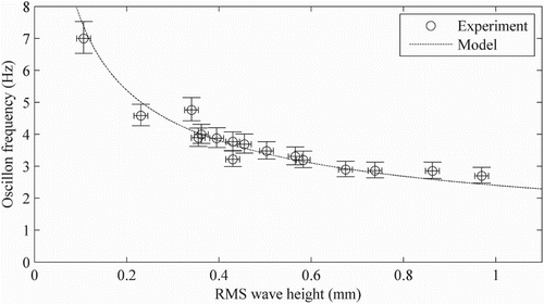
The errors seen between the measured and modelled frequencies are likely to be the combined effect of marginal errors in the measured surface velocity, RMS water surface roughness height, and characteristic spatial period. The surface velocity measurement, achieved by timing the transit of a floating tracer over a distance of 5 m, was subject to a potential human error in operating the timer of ± 0.25 s. This results in surface velocity measurements with a maximum error of ± 3.7%. The maximum error in the RMS wave height is estimated from the RMS wave height measured for still water. This was calculated by Krynkin, Horoshenkov, Nichols, and Tait (Citation2014) as 0.015 mm. Since the characteristic spatial period is calculated from the extremum values of the temporal cross-correlation functions of wave probe pairs, the error is expected to be governed by the variability of the temporal cross-correlation. This can be seen in Horoshenkov et al. (Citation2013) to be approximately ± 5%, and so the characteristic spatial period is deemed to be accurate to within ± 5%. The potential errors in these quantities are combined to determine the potential error in the oscillon frequency estimation, and are shown by the error bars in Fig. .
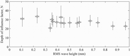
While the theoretical curve matched the experimental data well, using the presented equation to predict an oscillon frequency from a measured depth of influence, or vice versa, would rely on knowledge of the depth of influence factor, . From the data presented here it appears that the value of
is relatively constant. shows the N value calculated directly for each flow condition according to Eq. (9), with error bars defined according to the aforementioned potential measurement errors. While there is some variability, the value of
is generally within the expected error, and its value does not appear to vary systematically with the RMS wave height. Indeed, the average ratio of the depth of free surface influence to the flow depth suggested by the turbulent length scales of Savelsberg and van de Water (Citation2009) is 0.2, while the average ratio of RMS wave height to flow depth shown by Horoshenkov et al. (Citation2013) is 0.007, giving an average ratio of depth of influence to RMS wave height of
. This may indicate that for water at moderate temperatures the value of
could be a constant, though the dependence of
on temperature and hence viscosity still needs to be established. It would also appear reasonable that as the relative submergence changes, the influence, proximity and porosity of the bed may become important.
4.3 Relationship with near-bed processes
The pressure fluctuations induced by the free surface oscillon behaviour may also relate to the burst and sweep behaviour that is thought to control the generation of coherent flow structures near to the bed (Nakagawa & Nezu, Citation1981; Roussinova, Biswas, & Balachandar, Citation2010; Shvidchenko & Pender, Citation2001). It was therefore decided to compare the oscillon period with the expected period of near-bed coherent flow structure generation. Nezu and Nakagawa (Citation1993) defined a normalized mean bursting period:
(13)
where
is the mean temporal period between bursting events. They show that the near-bed normalized mean bursting period is generally in the region
. Nikora and Goring (Citation2000b) showed, for a range of turbulent flows over static and weakly mobile rough beds, that the normalized bursting period was within this range only for the lower 10% of the flow, and that the period increased beyond
toward the free surface. This increase was attributed to the thresholding used to identify bursts, and could also relate to the dissipation and amalgamation of structures as they rise and advect (Yalin, Citation1992). An equivalent non-dimensional period was calculated for the oscillons in this study as
. This period was generally found to be within the
range described by Nezu and Nakagawa (Citation1993), and also shows a slight increase with the surface velocity, a phenomenon remarked upon by Nikora and Goring (Citation2000b) in the context of sub-surface burst events. These comparisons suggest a linkage between the dynamic motion of the free surface oscillons and the occurrence of near-bed bursting events that generate turbulent structures. shows the oscillon frequency as a function of depth, and the frequency of near-bed bursts estimated from Eq. (13) as:
(14)
where a representative normalized bursting period of
is used, the centre of the typical near-bed range shown by Nezu and Nakagawa (Citation1993) and Nikora and Goring (Citation2000b).
Figure 10 Oscillon frequency and bursting frequency (calculated according Nezu & Nakagawa, Citation1993) as a function of the flow depth
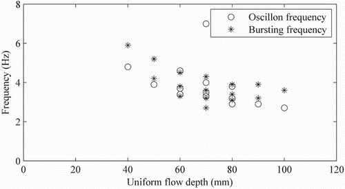
That the normalized period of the oscillons relates well with the observed near-bed bursting period, but less so with the bursting periods shown by Nikora and Goring (Citation2000b) above , suggests that the oscillon period is directly linked to the near-bed bursting phenomenon. This could indicate that the oscillon motion is a significant process that instigates near-bed bursting events via the influence of oscillon-induced pressure fluctuations.
5 Conclusions
The primary message of this paper is that a mechanically-based model can be used to describe the local dynamic response of a turbulent free surface. The experimental data confirm the existence of free surface oscillons in turbulent flow. The results support the hypothesis that the apparently complex nature of a dynamic flow surface can be understood simply by each of the individual surface deformations behaving according to simple harmonic motion.
The frequency of free surface oscillons has been shown to be a function of the RMS water surface roughness height and the depth of influence factor of the free surface oscillons. These dependencies suggest that the relationship is irrespective of the longitudinal and transverse size or shape of the surface disturbances, and hence can be extended to other fluids, large-scale flows, and natural river flows so long as the effects of surface tension remain small. If surface tension becomes large, then the theory can still apply but surface tension effects must be accounted for. The discovered relationship allows for a radically new understanding of free surface roughness whereby the complex surface pattern can be described as a number of temporally and spatially distributed and overlapping oscillons, each responding according to simple harmonic motion.
Oscillons may be generated by a number of processes, including but not limited to the influence of sub-surface coherent turbulent flow structures. In the presented flow conditions it is likely that they are induced by turbulent structures generated quasi-stochastically by the flow. This assertion was supported by the observation that the oscillon frequency was linked to the estimated bursting frequency. However, the model is theoretically applicable to any water surface where an area of the surface is displaced vertically and then allowed to return to equilibrium under gravity.
The oscillon process acts alongside the appearance of new deformations, the dissipation of older features, and perhaps also the propagation of gravity waves as reported by Savelsberg and van de Water (Citation2009). Together, these processes may capture the true and complete dynamic nature of turbulence induced free surface roughness. This allows the conclusion that the apparently complex dynamic nature of flow surfaces can be decomposed into four physical processes: (1) new structures impinge on the free surface and form local deformations; (2) these deformations behave as oscillons according to simple harmonic motion; (3) these oscillons may generate gravity waves that propagate radially and interfere; (4) individual features are eventually dissipated by viscous damping and are overwhelmed by newer, stronger features also generated by the underlying turbulence.
Notation
| = | cross sectional area of influenced volume (m2) | |
| = | flow depth (m) | |
| = | mean grain size (m) | |
| = | depth of influence (m) | |
| = | oscillon frequency (Hz) | |
| = | frequency of simple harmonic motion (Hz) | |
| = | Froude number | |
| = | net vertical force (N) | |
| = | acceleration due to gravity (m s−2) | |
| = | spring stiffness (N m−1) | |
| = | characteristic spatial period (m) | |
| = | deformation length (m) | |
| = | system mass (kg) | |
| = | depth of influence factor | |
| = | normalized bursting period | |
| = | Reynolds number | |
| = | bed slope | |
| = | mean bursting period (s) | |
| = | mean flow velocity (m s−1) | |
| = | free surface advection velocity (m s−1) | |
| = | surface deformation height (m) | |
| = | surface tension (N m−1) | |
| = | normalized deviate of surface elevation | |
| = | instantaneous surface elevation (m) | |
| = | angle of surface tension (rad) | |
| = | kinematic viscosity (m2 s−1) | |
| = | spatial lag (m) | |
| = | fluid density (kg m−3) | |
| = | spatial radius of correlation (m) |
Additional information
Funding
References
- Best, J. L., & Kostaschuk, R. A. (2002). An experimental study of turbulent flow over a low angle dune. Journal of Geophysical Research, 107(C9), 18-1–18-19. doi: 10.1029/2000JC000294
- Buffin-Bélanger, T., Roy, A. G., & Kirkbride, A. D. (2000). On large-scale flow structures in a gravel-bed river. Geomorphology, 32, 417–435. doi: 10.1016/S0169-555X(99)00106-3
- Dabiri, D. (2003). On the interaction of a vertical shear layer with a free surface. Journal of Fluid Mechanics, 480, 217–232. doi: 10.1017/S0022112002003671
- Eggers, J., & Riecke, H. (1999). Continuum description of vibrated sand. Physical Review E, 59(4), 4476–4483. doi: 10.1103/PhysRevE.59.4476
- Fujita, I., Furutani, Y., & Okanishi, T. (2011). Advection features of water surface profile in turbulent open-channel flow with hemisphere roughness elements. Visualization of Mechanical Processes, 1(3). doi:10.1615/VisMechProc.v1.i3.70
- Guo, X., & Shen, L. (2010). Interaction of a deformable free surface with statistically steady homogeneous turbulence. Journal of Fluid Mechanics, 658, 33–62. doi: 10.1017/S0022112010001539
- Horoshenkov, K. V., Nichols, A., Tait, S. J., & Maximov, G. A. (2013). The pattern of surface waves in a shallow free surface flow. Journal of Geophysical Research: Earth Surface, 118(3), 1864–1876. doi:10.1002/jgrf.20117
- Johnson, E. D., & Cowen, E. A. (2014). Remote monitoring of volumetric discharge based on surface mean and turbulent metrics. In A. J. Schleiss, G. de Cesare, M. J. Franca, & M. Pfister (Eds.), River Flow 2014 (pp. 1935–1941). London: CRC Press.
- Krynkin, A., Horoshenkov, K. V., Nichols, A., & Tait, S. J. (2014). A non-invasive acoustical method to measure the mean roughness height of the free surface of a turbulent shallow water flow. Review of Scientific Instruments, 85(11), 114902. doi: 10.1063/1.4901932
- Nakagawa, H., & Nezu, I. (1981). Structure of space–time correlations of bursting phenomena in an open-channel flow. Journal of Fluid Mechanics, 104, 1–43. doi: 10.1017/S0022112081002796
- Nelder, J., & Mead, R. (1965). A simplex method for function minimisation. The Computer Journal, 7, 308–313. doi: 10.1093/comjnl/7.4.308
- Nezu, I., & Nakagawa, H. (1993). Turbulence in open-channel flows. Rotterdam: Balkema.
- Nikora, V., & Goring, D. (2000a). Eddy convection velocity and Taylor’s hypothesis of ‘frozen’ turbulence in a rough-bed open-channel flow. Journal of Hydroscience and Hydraulic Engineering (JSCE), 18, 75–91.
- Nikora, V., & Goring, D. (2000b). Flow turbulence over fixed and weakly mobile gravel beds. Journal of Hydraulic Engineering, 126(9), 679–690. doi: 10.1061/(ASCE)0733-9429(2000)126:9(679)
- Rothman, D. H. (1998). Oscillons, spiral waves, and stripes in a model of vibrated sand. Physical Review E, 57(2), R1239–R1242. doi: 10.1103/PhysRevE.57.R1239
- Roussinova, V., Biswas, N., & Balachandar, R. (2010). Revisiting turbulence in smooth uniform open channel flow. Journal of Hydraulic Research, 46(2), 36–48. doi:10.1080/00221686.2008.9521938
- Roy, A. G., Buffin-Bélanger, T., Lamarre, H., & Kirkbride, A. D. (2004). Size, shape and dynamics of large-scale turbulent flow structures in a gravel-bed river. Journal of Fluid Mechanics, 500, 1–27. doi: 10.1017/S0022112003006396
- Savelsberg, R., & van de Water, W. (2009). Experiments on free surface turbulence. Journal of Fluid Mechanics, 619, 95–125. doi: 10.1017/S0022112008004369
- Shats, M., Xia, H., & Punzmann, H. (2012). Parametrically excited water surface ripples as ensembles of oscillons. Physical Review Letters, 108, 034502. doi: 10.1103/PhysRevLett.108.034502
- Shvidchenko, A. B., & Pender, G. (2001). Macroturbulent structure of open-channel flow over gravel beds. Water Resources Research, 37(3), 709–719. doi: 10.1029/2000WR900280
- Tamburrino, A., & Gulliver, J. S. (2007). Free surface visualization of streamwise vortices in a channel flow. Water Resources Research, 43. doi: 10.1029/2007WR005988
- Taylor, G. I. (1938) The spectrum of turbulence. Proceedings of the Royal Society A, 164, 476–490. doi: 10.1098/rspa.1938.0032
- Umbanhowar, P. B., Melo, F., & Swinney, H. L. (1996). Localized excitations in a vertically vibrated granular layer. Nature, 382, 793–796. doi: 10.1038/382793a0
- Ursell, F. (1949). On the heaving motion of a circular cylinder on the surface of a fluid. The Quarterly Journal of Mechanics and Applied Mathematics, 2(2), 218–231. doi: 10.1093/qjmam/2.2.218
- Walker, D. T., Leighton, R. I., & Garza-Rios, L. O. (1996). Shear-free turbulence near a flat free surface. Journal of Fluid Mechanics, 320, 19–51. doi: 10.1017/S0022112096007446
- Ward, S. N., & Asphaug, E. (2000). Asteroid impact tsunami: A probabilistic hazard assessment. Icarus, 145(1), 64–78. doi: 10.1006/icar.1999.6336
- Yalin, M. S. (1992). River mechanics. Oxford: Pergamon Press.

