Abstract
An analysis of the MOX critical experiments BASALA was performed to verify the pin-by-pin core analysis method using a three-dimensional direct response matrix. The BASALA experiments simulate full MOX BWR cores, and they were carried out in the EOLE critical facility of the French Atomic Energy Commission (CEA) by the Nuclear Power Engineering Corporation (NUPEC) in collaboration with CEA. The BASALA experimental cores are very heterogeneous because their size is much smaller than that of commercial power plants. The main features of the pin-by-pin core analysis method using the three-dimensional direct response matrix are that the response matrix can reflect the intra-assembly heterogeneous effect, the diffusion approximation is not involved, and the fuel rod fission rate can be directly evaluated. The maximum difference of the critical k-effective values among all nine cores analyzed was about 0.4% Δk. The root mean square differences between the calculated and measured radial fuel rod fission rate distributions in the test assembly of all cores were within 1.8% and nearly comparable to measurement error. The calculated results of the reactivity worth agreed with the measured results within 9%. These good agreements mean that the pin-by-pin core analysis method using the three-dimensional direct response matrix accurately reflects the effects of the intra- and inter-assembly heterogeneities in heterogeneous systems like the BASALA experimental cores.
1. Introduction
As nuclear reactor fuel and core designs have become more advanced, more precise neutronic analysis methods are desired. One typical request is for a more precise treatment of the effects of the intra- and inter-assembly heterogeneities in core analysis. A Monte Carlo method is one of the suitable methods for this purpose, because it can accurately treat any geometry and physical process Citation[1–Citation3]. However, it has the disadvantage of needing a long computational time to reduce statistical uncertainty. This is why Monte Carlo calculations are not applied to BWR core analysis in which neutronic and thermal-hydraulic calculations need to be iterated until the thermal-power and coolant-flow distributions converge.
To utilize the advantage of the Monte Carlo method for core analysis, the direct response matrix method using Monte Carlo calculations has been developed Citation[4–Citation9]. In this method, neutron behaviors in a fuel assembly are classified into four fundamental reaction processes represented by four types of sub-response matrices. These four sub-response matrices can be obtained by an ordinary single fuel assembly calculation using a Monte Carlo method, and the response matrix, which is dependent on a core eigenvalue k, is recomposed from them. The response matrix in the direct response matrix method can thus be obtained directly by a heterogeneous fuel assembly calculation. This means that the intra-assembly heterogeneous information is preserved in the response matrix in the direct response matrix method. Since Monte Carlo calculations are needed for only the fuel assembly calculations, the computational time for core analysis is short enough for practical application.
To verify the pin-by-pin core analysis method using the three-dimensional direct response matrix, Hino et al. Citation[6] carried out an analysis of cold critical experiments for commercial power plants. They obtained standard deviations and maximum differences in the evaluated critical k-effective values of 0.07% Δk and 0.19% Δk for a BWR5 plant, and 0.11% Δk and 0.25% Δk for an ABWR plant, respectively. The critical k-effective values could be evaluated with relatively small variations for both types of plants against various withdrawal patterns of control rods.
This article describes the analysis results of the MOX critical experiments BASALA Citation[10–Citation12] for further verification of the pin-by-pin core analysis method using the three-dimensional direct response matrix.
2. Analysis method
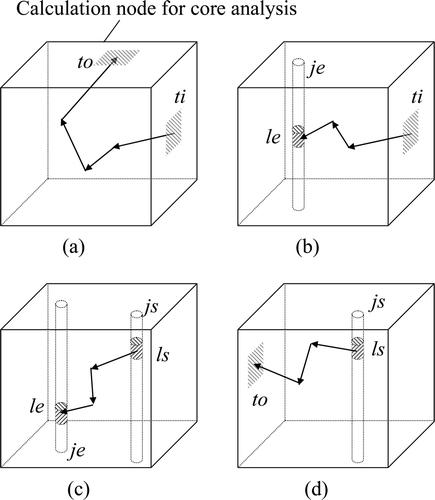
In core analysis, a reactor core system is divided intoa large number of equal-sized nodes. Each node corresponds to a region of a fuel assembly divided in the axial direction in BWR core analysis. In the direct response matrix method, neutron behaviors in a fuel assembly are classified into four fundamental reaction processes represented by four types of sub-response matrices. These sub-response matrices can be obtained by ordinary single fuel assembly calculations using a Monte Carlo method, and the response matrix is recomposed from them. Thus, the response matrix in the direct response matrix method can be obtained directly by heterogeneous fuel assembly calculations. The direct response matrix method has two features in particular.
| • | The response matrix can reflect the intra-assembly heterogeneous effect on the global balance calculation. | ||||
| • | The diffusion approximation is not involved in any part of the calculation. | ||||
The four sub-response matrices are defined as follows.
| • | Transmission probability (Tsi ,ti,gi→so,to,go ): the probability that a neutron entering from the ti-th segment of the si-th surface at the gi-th energy group eventually exits to the to-th segment of the so-th surface at the go-th energy group. | ||||
| • | Neighbor-induced production probability (Ssi ,ti,gi→je,le ): the number of neutrons expected to be produced in axial zone le of fuel rod je by a fission reaction due to a neutron entering from the ti-th segment of the si-th surface at the gi-th energy group. | ||||
| • | Self-induced production probability (Ajs,ls →je,le ): the number of neutrons expected to be produced in axial zone le of fuel rod je by a fission reaction due to a neutron produced in axial zone ls of fuel rod js. | ||||
| • | Escape probability (Ljs,ls →so,to,go ): the probability that a neutron produced in axial zone ls of fuel rod js eventually exits to the to-th segment of the so-th surface at the go-th energy group. | ||||
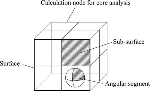
The sub-response matrices are illustrated in . The segment denoted above means not only the sub-surface obtained by dividing the surface but also the angular segment obtained by dividing the angle at which neutrons cross the surface, as illustrated in .
Figure 1. Schematic illustrations of sub-response matrices. (a) Transmission probability. (b) Neighbor-induced production probability. (c) Self-induced production probability. (d) Escape probability.
The response matrix can be recomposed with these four sub-response matrices in the form of a function of a core eigenvalue k. The k-dependent response matrix R(k) si,ti,gi →so,to,go is expressed as follows:
The relationship between the incoming and outgoing neutron partial currents is defined by the following equation based on the direct response matrix method:
The neutron production rate P(i) of fuel rod i can be represented by the following equation:
The fuel rod fission rate can be evaluated by dividing the fuel rod neutron production rate by the expected number of neutrons produced in a fission reaction.
Although, Equations (1) and (3) have a nested structure of summations that continues for an infinite number of generations, the calculated values saturate as the generation number increases. Thus, the summations can be limited to a practical number of generations.
3. Summary of MOX critical experiments BASALA
3.1. Experimental facility
The MOX critical experiments BASALA, which simulated full MOX BWR cores, were carried out in theEOLE critical facility of the Cadarache Center of the French Atomic Energy Commission (CEA) by the Nuclear Power Engineering Corporation (NUPEC) in collaboration with CEA and their associated industrial partners. The EOLE core tank has about a 1 m radius and about a 1 m height, and it was filled with light water. All measurements were conducted under the condition of an overflow water level, i.e. the water was about 200 mm higher than the top of the effective fuel length.
The critical adjustment was done by changing the number of the inserted fuel rods, and the minute reactivity adjustment was done by changing the amount of insertion of the pilot rod.
The fuel rods had the same geometry as the standard PWR 17 × 17 assembly with an outer diameter of 9.5 mm except that their fuel effective length was about 800 mm. The fuel pellets were composed of a mixed dioxide of plutonium and depleted uranium, and the fuel rods had Zry claddings. These rods were sealed by over-claddings to adjust the core moderation ratio and protect the rods during handling. The diameter of the over-cladding was 10.2 mm. Four types of MOX fuel rods, 3.0, 4.3, 7.0, and 8.7 wt% of Pu total content, were used. In part of the experiments, UO2 (4.9 wt%)–Gd2O3 (2.5 wt%) fuel rods and UO2 (3.7 wt%) fuel rods were also used.
3.2. Contents of BASALA experiments
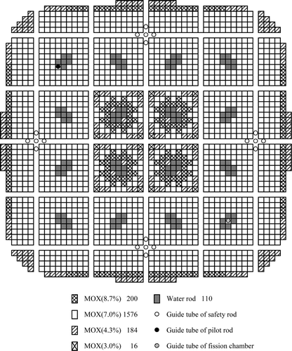
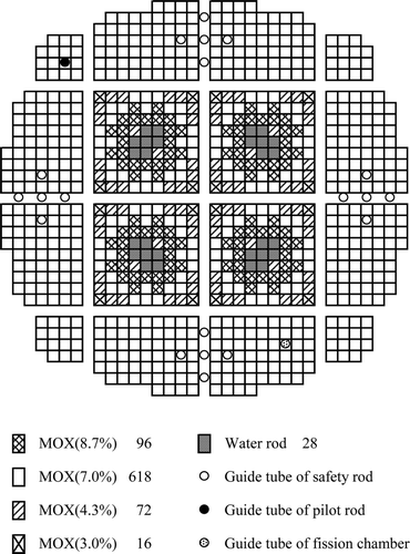
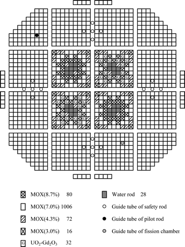
There were two series of BASALA experiments with two core configurations of different lattice pitches, called core 1 and core 2. The former simulated hot operation conditions of a BWR (in-channel void fraction of 40%) and the latter, cold conditions. In core 1, the fuel rod pitch in the assembly was 11.3 mm, the assembly pitch was 114.1 mm and the hydrogen to heavy metal atomic ratio (H/HM) was 5.0. In core 2, the fuel rod pitch, the assembly pitch and H/HM were 13.5 mm, 135.5 mm and 9.0, respectively. The core characteristics and the fuel assembly specifications are shown in . Core 1 consisted of a reference core and its derivative cores. The derivative cores of core 1 were the 2D void core, the UO2–Gd2O3 fuel rod inserted core, and the water rod core. All cores of core 1 were analyzed in this study. Core 2 also had a reference core and its derivative cores. The derivative cores thatwere analyzed in this study were the UO2–Gd2O3 fuel rod inserted core and the control blade insertedcore.
Table 1. Core characteristics and fuel assembly specifications of BASALA experiments.
3.2.1. Reference cores
The configurations of the reference cores of core 1 and core 2 are shown in and , respectively. The numbers in the figures are the numbers of fuel rods or water rods. Each core consisted of four assemblies of a 9 × 9 fuel rod array in the center of the core as a test region and several assemblies surrounding the test region as a driver region. In the test region, the assembly was composed of four types of MOX fuel rods and seven water rods. The driver region was mainly loaded with 7 wt% MOX fuel rods. The critical mass and radial fission rate distribution were measured.
3.2.2. UO2-Gd2O3 fuel rod inserted cores
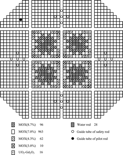
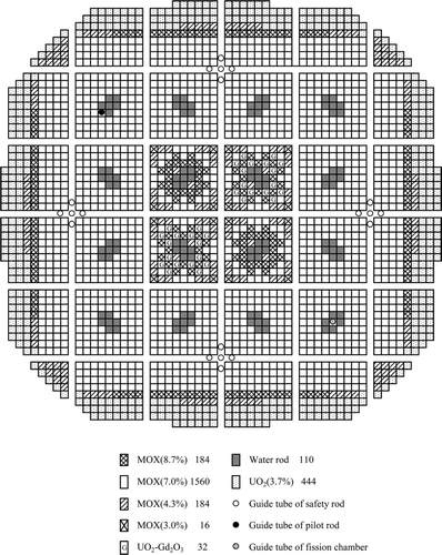
In two assemblies diagonally located in the test region (i.e. the upper right and lower left assemblies), 8 or 16 MOX fuel rods were replaced by UO2–Gd2O3 fuel rods. The core with eight UO2–Gd2O3 fuel rods inserted is called the 8Gd core, and that with 16 UO2–Gd2O3 fuel rods inserted is called the 16Gd core. The configurations of the 8Gd and 16Gd cores are shown in – . Measurements of the critical mass, radial fission rate distribution, and the reactivity worth of insertion of UO2–Gd2O3 fuel rods were carried out.
Figure 5. Configuration of 8Gd core for core 1. The percentages are wt % of Pu total content and the numbers are the numbers of each type of rod.
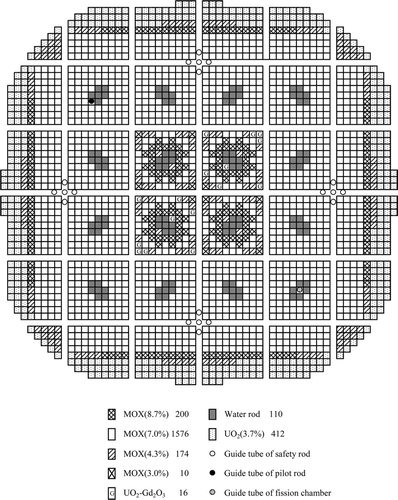
Figure 6. Configuration of 16Gd core for core 1. The percentages are wt % of Pu total content and the numbers are the numbers of each type of rod.
3.2.3. 2D void core
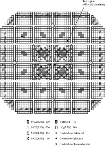
All fuel rods of the four assemblies in the test region had a thick over-cladding for the full rod length in order to simulate an in-channel void fraction of 65%. The configuration of the 2D void core is shown in . The critical mass, the radial fission rate distribution, and the reactivity worth of the increased void were measured.
3.2.4. Water rod core
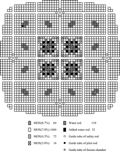
Each assembly in the test region had eight additional water rods replacing MOX fuel rods. The configuration of the water rod core is shown in . The critical mass, the radial fission rate distribution, and the reactivity worth of the additional water rods were measured.
3.2.5. Control blade inserted core
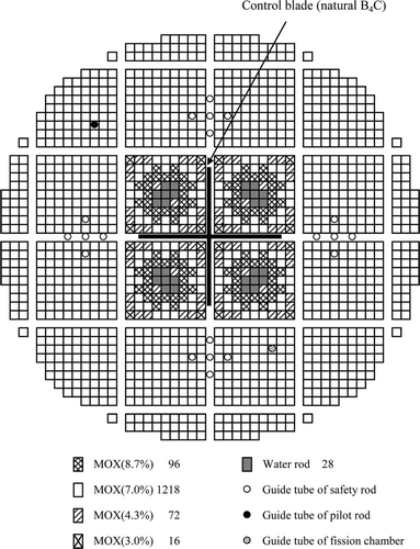
In the center of the test region, a cruciform control blade of B4C was inserted. The configuration of the control blade inserted core is shown in . The critical mass, the radial fission rate distribution, and the reactivity worth of the control blade were measured.
4. Analysis results
4.1. Analysis process
The sub-response matrices were evaluated with a three-dimensional infinite assembly system of a 9 × 9 fuel rod array, and the height of the system was 100 mm. For a partial assembly in the peripheral region, these matrices were evaluated with a three-dimensional infinite assembly system that was the same size as the assembly system of the full 9 × 9 fuel rod array and consisted of fewer fuel rods and water areas. The sub-response matrices of the reflector region were evaluated with the single three-dimensional assembly system consisting of two fuel nodes with a reflector node on their each top and bottom. The fuel nodes were the assembly of full 9 × 9 fuel rod array in the driver region, and the heights of the fuel and reflector nodes were 100 mm. The sub-response matrices were calculated by the fuel assembly analysis code VMONT Citation[13]. VMONT is based on a Monte Carlo neutron transport method, and uses a multi-group model for the neutron spectrum calculation for which the total number of energy groups is 190. The number of tracked neutrons was 2 × 10⁶. The statistical uncertainty of the neutron infinite multiplication factor was about 0.03% Δk and that of the fuel rod fission rate was about 0.3%. The nuclear data library was JENDL-3.2.
The number of sub-surfaces for each node was set to 4 × 4. Each fuel rod had four axial zones in a node theheight of which was 100 mm. These numbers of sub-surfaces and fuel rod axial zones were equal to those in the analysis of cold critical experiments of commercial power plants Citation[6]. Three cases were calculated about the numbers of angular segments for each sub-surface and energy groups in consideration that the size of the BASALA experimental cores were much smaller than that of commercial power plants. In the first case, there were four angular segments and three energy groups. These numbers were equal to those in the analysis of cold critical experiments of commercial plants Citation[6]. In the second case, there were 16 angular segments and three energy groups, and in the third case, there were 16 and nine, respectively. illustrates the sub-surfaces and angular segments. The energy group structures are shown in . This 9-group structure was the optimized one for the below 10-groups. It was separately confirmed that the effect was small even if the number of energy groups was increased further. The guide tubes and structure materials of lower and upper parts of the fuel rods were disregarded. Reflector nodes were set to three nodes at the top and bottom of the core and a minimum of three nodes at the side of the core. The boundary condition was reflective.
Figure 12. Illustrations of sub-surfaces and angular segments. (a) Number of sub-surfaces and angular segments : 4 × 4 and 4. (b) Number of sub-surfaces and angular segments : 4 × 4 and 16.
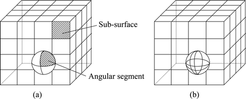
Table 2. Energy group structure for sub-response matrices.
The reactivity worth value was calculated from the k-effective values evaluated with the reference core and the core that substituted the test assemblies in the reference core with those of the derivative core.
4.2. Analysis results
4.2.1. Reference cores
4.2.1.1. Criticality
The calculated results of the critical k-effective values for the reference cores are shown in . For the first case in which the numbers of angular segments and energy groups were four and three, respectively, the critical k-effective values were about 1.023. For the second case in which the numbers were 16 and 3, the critical k-effective values were about 1.016 and about 0.7% Δk smaller than those of the first case. For the third case in which the numbers were 16 and 9, the critical k-effective values were about 1.009 and about 0.7% Δk smaller than those of the second case. This difference between the second and third cases was mainly caused by the difference of the neutron spectrum between fuel rods and reflectors in the fast energy region.
Table 3. Critical k-effective values for reference cores.
The average of the critical k-effective values was 1.0091 for the case in which the numbers of angular segments and energy groups were 16 and 9, respectively. In the analysis with the continuous energy Monte Carlo code MVP Citation[14] and JENDL-3.2 carried out by NUPEC Citation[12], the average of the critical k-effective values was 1.0086. The results calculated using the direct response matrix method agreed very well with the results calculated using the continuous energy Monte Carlo code. The difference between core 1 and core 2 was 0.18% Δk. The critical k-effective values could be evaluated with relatively small variations for both cores against different H/HM ratios.
4.2.1.2. Fission rate distribution
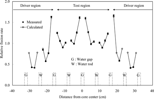
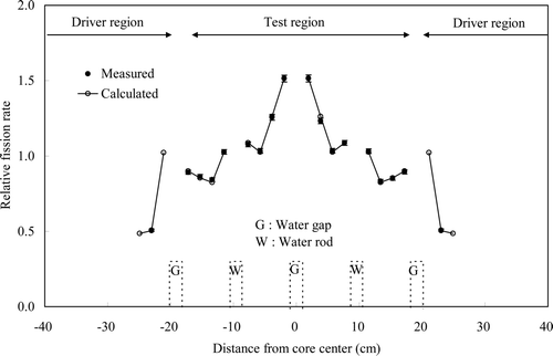
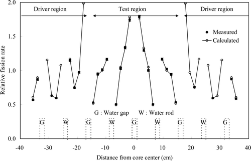
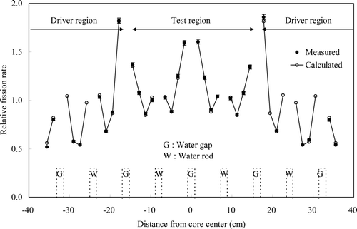
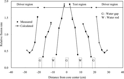
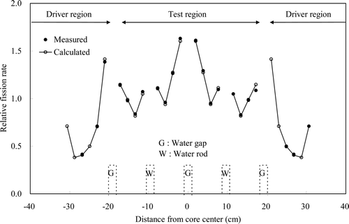
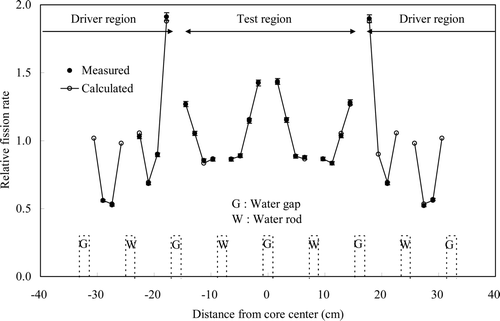
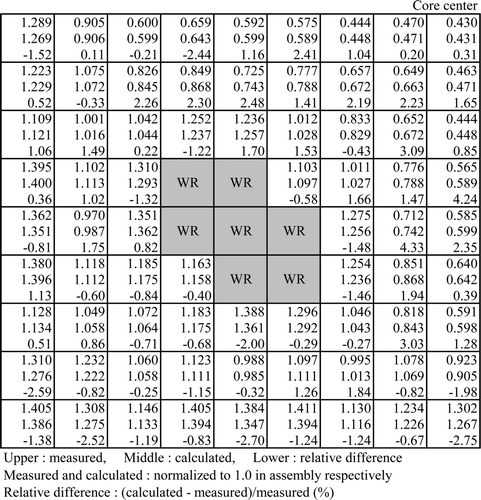
The measured and calculated fission rates were the integrated values of the total length of the fuel rod axial direction. shows the root mean square and maximum differences between the calculated and measured radial fuel rod fission rate distributions in the diagonal direction from the left bottom to the right top for the reference cores. The measured and calculated values were normalized to 1.0 in all compared fuel rods, respectively. The relative difference between calculated and measured values was defined by (calculated values – measured value)/measured value. The root mean square difference was defined by the root mean square of the relative differences of each fuel rod. The measurement error was 1.5%. When the numbers of angular segments and energy groups were increased, the root mean square and maximum differences became small. This was because the differences in the peripheral fuel rods became small. The effect was large especially in core 2. This was because the size of core 2 was very small, and the contribution of the peripheral fuel rods to reactivity was large. For the case in which the numbers of angular segments and energy groups were 16 and 9, respectively, the root mean square differences of both cores were within 1.4% and less than the measurement error. The maximum differences of both cores were within 3.2%. In the analysis with MVP, the root mean square differences of both cores were 1.6% Citation[12]. The direct response matrix method and MVP were almost equal in accuracy. The differences between the calculated and measured values became somewhat large in both the direct response matrix method and MVP because there was no symmetry with the center in the measured values. and compare the measured and the calculated radial fuel rod fission rate distributions in the diagonal direction from the left bottom to the right top for the case in which the numbers of angular segments and energy groups were 16 and 9, respectively. The calculated results well reproduced the gross and local heterogeneous fuel rod fission rate distribution in both cores. The results calculated using the direct response matrix method agreed very well with the measured results.
Table 4. Root mean square and maximum differences of fuel rod fission rate distribution between calculation and measurement in diagonal direction for reference cores (unit:%).
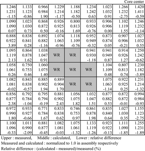
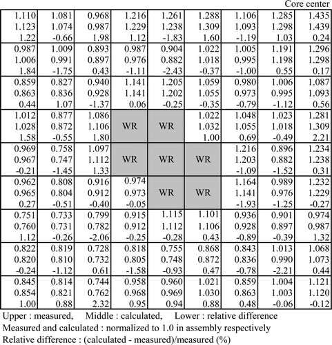
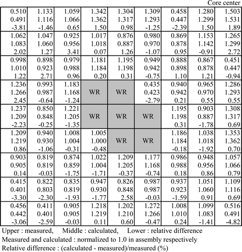
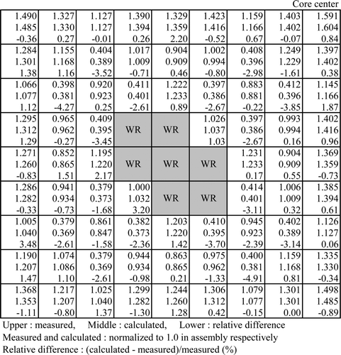
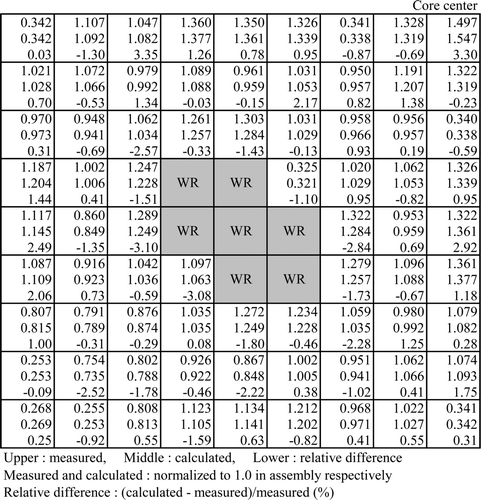
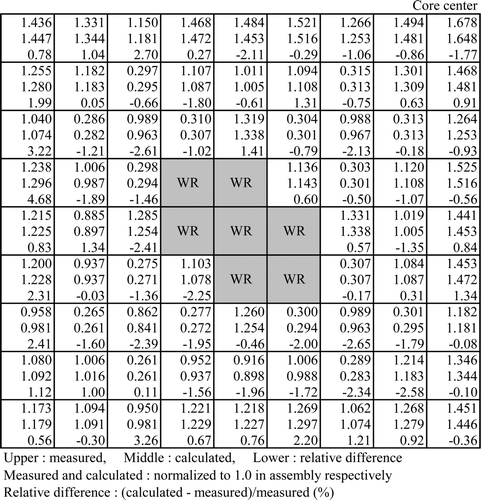
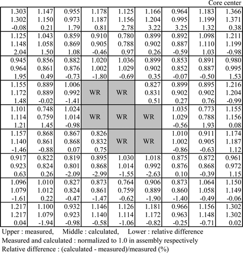
summarizes the root mean square and maximum differences between the calculated and measured results for the radial fuel rod fission rate distributions in the left bottom assembly in the test region for the reference cores. The measured and calculated values were normalized to 1.0 in all fuel rods, respectively. Even if the numbers of angular segments and energy groups were increased, the root mean square and maximum differences hardly changed. This was because the test assembly was in the center part, and the influence of the reflectors was very small. The root mean square differences of both cores were within 1.4% for all cases and less than the measurement error. The maximum differences of both cores were within 3.9% for all cases. These results meant that the case in which the numbers of angular segments and energy groups were four and three, respectively, had enough accuracy except in the peripheral regions. In the analysis with MVP, the root mean square differences of both cores were within 1.5% Citation[12]. The direct response matrix method and MVP were almost equal in accuracy. The differences between the calculated and measured values became somewhat large in both the direct response matrix method and MVP because there was no diagonal symmetry in the measured values. and show the measured and calculated results and the differences between them for the radial fuel rod fission rate distributions in the left bottom assembly in the test region for the case in which the numbers of angular segments and energy groups were 16 and 9, respectively. The results calculated using the direct response matrix method again agreed very well with the measured results.
Table 5. Root mean square and maximum differences of fuel rod fission rate distribution between calculation and measurement in test assembly for reference cores (unit:%).
4.2.2. Derivative cores
For the derivative cores, only the results are shown of the case in which the numbers of angular segments and energy groups were 16 and 9, respectively.
4.2.2.1. Criticality
The calculated results of the critical k-effective values including those of the reference cores are shown in . The average of the critical k-effective values of core 1 was equal to that of core 2. In core 1, the difference in the critical k-effective values for the reference and the derivative cores was less than 0.1% Δk, and the standard deviation was 0.05% Δk. The critical k-effective values of the derivative cores agreed very well with that of the reference core. In core 2, the difference in the critical k-effective values for the reference and the derivative cores was about 0.4% Δk, and the standard deviation was 0.20% Δk. These values were larger than those of core 1 and that was mainly caused by the underestimation in the reference core and the overestimation in the control blade inserted core. The critical k-effective value of the reference core of core 2 was about 0.2% Δk smaller than the average of the critical k-effective values of core 2. The size of the reference core of core 2 was very small as shown in , so it might be necessary to increase the number of the sub-surfaces and angular segments for better analysis of the reference core of core 2. The critical k-effective value of the control blade inserted core was about 0.2% Δk larger than the average of the critical k-effective values of core 2. This might be caused by the large contribution of the peripheral assemblies to reactivity because the powers of the assemblies in the central region were lower than those of other cores. But the 0.2% Δk was comparatively smaller than the control blade worth which was about 10% Δk and is shown later. In the analysis with MVP, the average of the critical k-effective values was 1.0088 Citation[12]. The average of the k-effective values calculated using the direct response matrix method agreed with the one calculated using the continuous energy Monte Carlo code within 0.14% Δk.
Table 6. Critical k-effective values.
4.2.2.2. Fission rate distribution
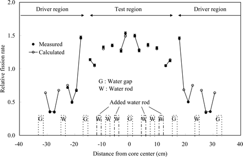
– compare the measured and calculated radial fuel rod fission rate distributions in the diagonal direction from the left bottom to the right top. The measured and calculated values were normalized to 1.0 in all compared fuel rods, respectively. The calculated results well reproduced the gross and local heterogeneous fuel rod fission rate distribution in all cores. shows the root mean square and maximum differences between the calculated and measured radial fuel rod fission rate distributions in the diagonal direction including those of the reference cores. The root mean square differences were within 2.5%, and the maximum differences were within 8.0%. The root mean square and maximum differences of the 8Gd and 16Gd cores of core 1 were slightly larger than those of the other cores. This was mainly caused by the overestimation by the calculation for the fission rate of fuel rods in the peripheral region. In the 8Gd and 16Gd cores of core 1, the fuel rods located more outside compared with the other cores were measured. In the analysis with MVP, the root mean square differences were within 1.9% Citation[12]. The root mean square differences in this method were slightly larger than those in MVP. The differences between the calculated and measured values became somewhat large in both the direct response matrix method and MVP because there was no symmetry with the center in the measured values.
Table 7. Root mean square and maximum differences of fuel rod fission rate distribution between calculation and measurement in diagonal direction (unit:%).
Figure 23. Fuel rod fission rate distribution of control blade inserted core for core 2 (diagonal direction).
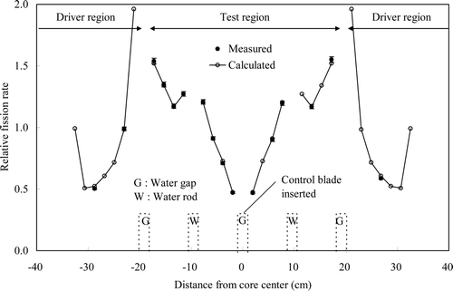
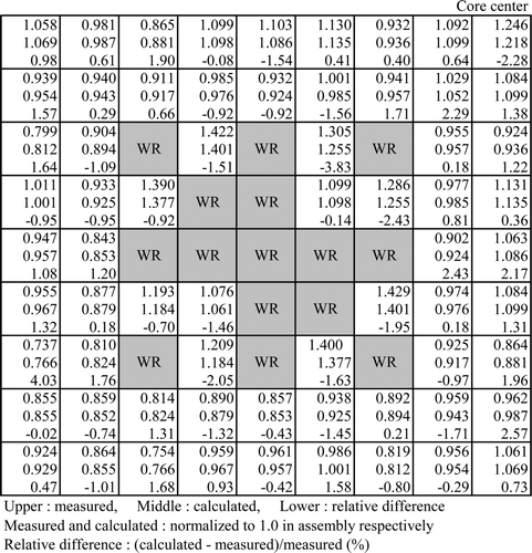
– show the measured and calculated results and the differences between them for the radial fuel rod fission rate distributions in the left bottom assembly in the test region. The measured and calculated values were normalized to 1.0 in all fuel rods, respectively. summarizes the root mean square and maximum differences between the calculated and measured results for the radial fuel rod fission rate distributions in the left bottom assembly in the test region including those of the reference cores. The root mean square differences of all cores were within 1.8% and nearly comparable to the measurement error. The maximum differences of all cores were within 4.9%. In addition, the root mean square and maximum differences of the derivative cores were almost comparable to those of the reference cores. The results calculated using the direct response matrix method agreed well with the measured results. In the analysis with MVP, the root mean square differences were within 1.6% Citation[12]. The direct response matrix method and MVP were almost equal in accuracy. The differences between the calculated and measured values became somewhat large in both the direct response matrix method and MVP because there was no diagonal symmetry in the measured values.
Table 8. Root mean square and maximum differences of fuel rod fission rate distribution between calculation and measurement in test assembly (unit: %).
4.2.2.3. Reactivity worth
The measured and calculated reactivity worth values are shown in . The measured values shown in the table were the ones measured by the fuel rod equivalence method. The measurement error of each reactivity worth was about 6%. The calculated results, except the 2D void worth agreed with the measured results within 5%, which was less than the measurement error. The calculated result of the 2D void worth agreed with the measured result within 9%, which was about one and a half times the measurement error, and the difference between the calculated and measured results of the 2D void worth was only 0.12% Δk. The results calculated using the direct response matrix method agreed well with the measured results. In the analysis with MVP, the C/E values were from 0.98 to 1.04 Citation[12]. The direct response matrix method and MVP were almost equal in accuracy except regarding the 2D void worth.
Table 9. Comparison of reactivity worth between calculation and measurement.
5. Conclusion
An analysis of the MOX critical experiments BASALA was done in order to verify the pin-by-pin core analysis method using the three-dimensional direct response matrix. The BASALA experiments simulated full MOX BWR cores, and were carried out in the EOLE critical facility of the Cadarache Center of the French Atomic Energy Commission (CEA) by the Nuclear Power Engineering Corporation (NUPEC) in collaboration with CEA. The BASALA experimental cores were very heterogeneous because their size was much smaller than core sizes of commercial power plants. In the direct response matrix method, the response matrix could be formalized by four sub-response matrices that could be evaluated by an ordinary single heterogeneous fuel assembly calculation with a Monte Carlo method. With these sub-response matrices, the response matrix dependent on a core eigenvalue k could be recomposed. This meant that the information about the intra-assembly heterogeneity was preserved in the response matrix used in the core analysis.
The average of the critical k-effective values of the nine analyzed cores was 1.0102, which was nearly comparable to the analysis results obtained by NUPEC using the continuous energy Monte Carlo code MVP. The maximum difference of the critical k-effective values among all cores was about 0.4% Δk. The root mean square differences of all cores between the calculated and measured radial fuel rod fission rate distributions in the diagonal direction from the left bottom to the right top were within 2.5%. The root mean square differences of all cores between the calculated and measured radial fuel rod fission rate distributions in the test assembly were within 1.8% and nearly comparable to measurement error. The direct response matrix method and MVP were almost equal in accuracy for evaluating radial fuel rod fission rate distributions. The calculated reactivity worth results, except for the 2D void worth, agreed with the measured results within 5%, which was less than the measurement error. The calculated results of the 2D void worth agreed with the measured results within 9%, which was about one and a half times the measurement error. The results calculated using the direct response matrix method agreed well with the measured results. The direct response matrix method and MVP were almost equal in accuracy for evaluating the reactivity worth. These good agreements confirmed that the pin-by-pin core analysis method using the three-dimensional direct response matrix accurately reflected the effects of the intra- and inter-assembly heterogeneities in heterogeneous systems like the BASALA experimental cores.
References
- Spanier , J. and Gelbard , E.M. 1969 . Monte Carlo Principles and Neutron Transport Problems , Massachusetts : Addison-Wesley Publishing Company, Reading .
- Lewis , E.E. and Miller , W.F. Jr. 1993 . Computational Methods of Neutron Transport , La Grange Park , IL : American Nuclear Society, Inc .
- Nakagawa , M. and Mori , T. 1993 . Whole core calculations of power reactors by use of Monte Carlo method . J. Nucl. Sci. Technol , 30 : 692
- Moriwaki , M. , Ishii , K. , Maruyama , H. and Aoyama , M. 1999 . A new direct calculation method of response matrices using a Monte Carlo calculation . J. Nucl. Sci. Technol , 36 : 877 – 887 .
- Ishii , K. , Hino , T. , Mitsuyasu , T. and Aoyama , M. 2009 . Three-dimensional direct response matrix method using a Monte Carlo calculation . J. Nucl. Sci. Technol , 46 : 259 – 267 .
- Hino , T. , Ishii , K. , Mitsuyasu , T. and Aoyama , M. 2010 . BWR core simulator using three-dimensional direct response matrix and analysis of cold critical experiments . J. Nucl. Sci. Technol , 47 : 482 – 491 .
- Hino , T. , Ishii , K. , Mitsuyasu , T. and Aoyama , M. Development of core analysis method using three-dimensional direct response matrix . Proceedings of international conference on physics of reactors (PHYSOR2008 . September 14–19 . log657
- Mitsuyasu , T. , Ishii , K. , Hino , T. and Aoyama , M. Development of spectral history methods for pin-by-pin core analysis using three-dimensional direct response matrix . Proceedings of international conference mathematics and computation, reactor physics and environmental analysis in nuclear applications (M&C2009 . May 3–7 . pp. 200688
- Ishii , K. , Hino , T. , Mitsuyasu , T. and Aoyama , M. Development of pin-by-pin core analysis method using three-dimensional direct response matrix . Proceedings of international congress on advances in nuclear power plants (ICAPP’09 . May 10–14 . pp. 9401
- Yamamoto , T. , Iwata , Y. , Umano , T. , Kanda , R. , Cathalau , S. , Fougeras , P. , Thiollay , N. , Blaise , P. , Santamarina , A. and Nigon , J.L. BWR MOX core physics experiments and preliminary analysis . Proceedings of international conference on new frontiers of nuclear technology; reactor physics, safety and high-performance computing (PHYSOR2002 . October 7–10 .
- Yamamoto , T. , Umano , T. , Kanda , R. , Sasagawa , M. , Ishii , K. , Ando , Y , Takada , N and Kan , T . Core physics experiments and their analyses of high moderation full MOX BWR . Proceedings of international conference on global environment and advanced nuclear power plants (GENES4/ANP2003 . September 15–19 .
- Ishii , K. , Ando , Y. , Takada , N. , Kan , T. , Sasagawa , M. , Kikuchi , T. , Yamamoto , T. , Kanda , R. and Umano , T. 2005 . Analysis of high moderation full MOX BWR core physics experiments BASALA . Trans. At. Energy Soc. Jpn , 4 : 45 – 65 . [in Japanese]
- Morimoto , Y. , Maruyama , H. , Ishii , K. and Aoyoma , M. 1989 . Neutronic analysis code for fuel assembly using a vectorized Monte Carlo method . Nucl. Sci. Eng , 103 : 351 – 358 .
- Mori , T. , Nakagawa , M. and Sasaki , M. 1992 . Vectorization of continuous energy Monte Carlo method for Neutron transport calculation . J. Nucl. Sci. Technol , 29 : 325 – 336 .
