Abstract
Interaction between metallic fuel and steel structures is one of the predominant phenomena in the progress of core disruptive accidents of Sodium-cooled fast reactor. In this study, the atomic diffusion across the interface between Pu and Fe was investigated by using molecular dynamics. The simulation was performed by using Modified Embedded Atom Method (MEAM). The interactions between plutonium and iron atoms were calculated by using the newly developed potential model determined so as to reproduce the material properties of PuFe2 and Pu6Fe. The material properties of the compounds predicted with the developed potential were in good agreement with the referenced data. The dissolution or melting at the interface between solid Fe and solid or liquid Pu were simulated by contacting semi-infinite slabs (or liquid layer) of them. Dissolution was observed for all the tested temperature conditions from 800 K up to 1700 K. The melting at the interface was also observed on the interface between solid Fe and PuFe2 slabs at the temperature approximately 100 K below the melting temperature of PuFe2 obtained based on the present model.
1. Introduction
Sodium-cooled fast reactor (SFR) is one of the efficient choices of the next-generation nuclear energy supplier. For the analyses of hypothetical core disruptive accidents (CDAs) for such type of reactor, it is of utmost importance to estimate accurately the recriticality induced by the concentration of the molten fuel. When the fuel and structure meet with each other, reaction between metals would occur and induce local complex flow of molten material. Especially the reactions between metals which form the eutectic systems, e.g. U-Fe, Pu-Fe, Fe-Zr, progress at the temperatures even lower than either of the melting temperatures of the pure metals. Thus the evaluation of such metal reactions is a crucial matter to estimate the process of the accidents.
Molecular dynamics (MD), which has been developed especially in these two decades, is one of the powerful techniques for the elucidation of the detailed mechanism of the interaction on the interface between two metals. In the framework of MD, Embedded Atom Method (EAM) [Citation1] and its advanced model, Modified EAM (MEAM) [Citation2], are most commonly used for analyzing the behaviors of metal atoms. Potential parameters for various kinds of metals have been proposed (e.g. [Citation3–Citation7]).
Alloy and eutectic systems have been investigated with EAM or MEAM as well as pure component systems. Webb et al. [Citation8] investigated the melting temperature of Ag-Cu system by using EAM and obtained good consistency with the phase diagram obtained from experiments. They also analyzed intrusion phenomena of liquid Ag into solid Cu plate in their eutectic reaction. Chen et al. [Citation9] performed MD simulation on the diffusion bonding of solid Cu and solid Ag and found that the increase in the system pressure enhances the mutual diffusion at the interface. One of the present authors [Citation10] analyzed the diffusion on the interface between Ag and Cu, and found that the location of liquefaction (i.e. solid-liquid interface), even on microscopic scale, can be estimated by applying the local atomic fraction of the two metals to the phase diagram. He also shows that the surface melting on the interface between the two solid metals remarkably contribute to the mutual diffusion at the interface, which associates with the eutectic melting. Fe-C [Citation11] and Fe-Cu [Citation12] systems have been also examined by several researchers.
However, little attention has been devoted to metallic reaction including nuclear fuel materials. Pu is the only nuclear fuel material for which the potential models based on MEAM have been developed. Baskes [Citation5] proposed the MEAM potential parameters for Pu and investigated the complex behavior of Pu in terms of the distribution of electron density. Baskes et al. [Citation13] calculated the lattice vibration of Pu-Ga alloy by using the potential model developed in the earlier study [Citation14].
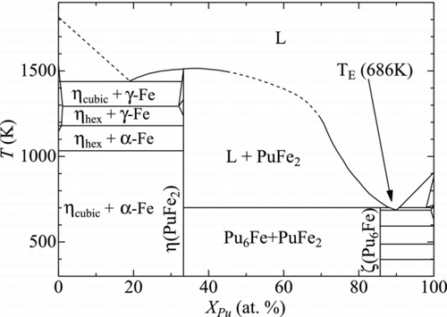
In the present work, we focus on the reaction between Pu and Fe metals, the possible reaction to be undergone in CDAs of SFRs. In Pu-Fe system, an eutectic interaction is observed between Pu-metal and Pu6Fe as shown in [Citation15, Citation16]. The eutectic temperature is reported to be 686 K, which is lower than the melting temperatures of two terminate materials, such as Pu (913 K) and Fe (1811 K). There are two intermetallic compounds in the Pu-Fe system, PuFe2 and Pu6Fe. PuFe2 melts congruently at 1513 K. Pu6Fe decomposes peritectically. Between PuFe2 and Fe-metal, there is another eutectic interaction and the eutectic temperature is reported to be 1440 K.
The objective of this study is to provide the potential parameters of MEAM for Pu-Fe system and to discuss the mutual diffusion and liquefaction on the Pu-Fe interface. In Section 2, the formalism of MEAM is briefly described. In Section 3, the determination of the potential parameters for the interaction between Pu and Fe atoms is mentioned. The calculational results on the material properties of PuFe2 and Pu6Fe are presented in Section 4.1. Section 4.2 introduces the analysis results on the atomic diffusion on the interface between Pu and Fe, and in Section 4.3, the evaluation of the liquefaction at the interface between PuFe2 and Fe is made. Section 5 gives a summary of this paper.
2. Formalism of MEAM
The analyses in this study are carried out by using the Modified Embedded Atom Method (MEAM) [Citation2]. In the MEAM, the total energy of atoms is described, similar to the original Embedded Atom Method [Citation1], as,
The atomic electron density is given as
The density ![]() is related with ρ(h)
i
(h = 0, 1, 2, 3) by the following expressions,
is related with ρ(h)
i
(h = 0, 1, 2, 3) by the following expressions,
Angular screening is used to limit the interaction range between atoms, as well as the radial cut off often used in MD calculations. With this screening, the interaction between atoms is screened by atoms which are located near the line segment connecting the two concerned atoms. Details of this technique are found in the reference [Citation3].
In this study, Pu was simulated by using the model parameters proposed by Baskes [Citation5]. Plutonium has six allotropes depending on the temperature. This model reproduces the energies and the lattice constants for all the observed solid phases in the experiments. The melting temperature obtained by the model, which is the most important property for the present study, also shows quite good agreement with the experimental value of 913 K.
For Fe, we employed the potential model developed by Lee et al. [Citation6]. This model takes into account the contribution of the second nearest neighbor (2NN) atoms, which is not considered in the original MEAM by Baskes. The form of φ is slightly changed from Equation (Equation6) as
The electron density is expressed as,
3. Development of interatomic potential parameters
The interatomic potential parameters between unlike (Pu and Fe) atoms were determined so as to reproduce the material properties of the two intermetallic compounds in Pu-Fe systems, i.e., PuFe2 and Pu6Fe.
The referred experimental parameters were the formation enthalpy ΔHf , the lattice constants a 0 (and c 0 for Pu6Fe), and the melting temperature Tm , which are given in Table . The values with asterisks are those referred as the target value for the determination of the parameters in this study.
Table 1 Material properties of PuFe2 and Pu6Fe
Along with the above parameters, the value of the bulk modulus B is essential for the determination of the potential parameters in MEAM formalism. In this study, the first principle calculations with VASP [Citation20] and WIEN2k [Citation21] codes were performed to obtain the value of B for PuFe2.
VASP code was used with the spin-polarized generalized gradient approximation (SGGA+U). WIEN2k is based on Full-potential Linearized Augmented Plane Wave Method (FLAPW), and SGGA is also applied in this code. More details for these codes are available in the references shown at the end of this paper.
The basic cell consists of one lattice of PuFe2 crystal, and 8 × 8×8 and 10 × 10 × 10 of k points were used for VASP and WIEN2k calculations, respectively. The cutoff wave number is set on the basis of kmax = 7/Rmt where Rmt is the smallest atomic sphere radius.
The obtained results of EU by VASP and WIEN2k are shown in . The results obtained with the two codes show trends similar with each other. The value of B was calculated by using Equation (Equation8) with the constants obtained by fitting Equation (Equation7) to the calculation data. The obtained values of B were 216 GPa for VASP and 193 GPa for WIEN2k.
Figure 2 Relation between total energy Eu and lattice size a 0 of PuFe2 obtained with VASP and WIEN2k
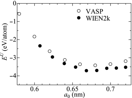
The lattice constant and the cohesive energy were also available from the calculation data through similar procedures. The obtained lattice constant (0.670 or 0.681 nm), however, was smaller than the experimental value (0.7189 nm). The calculated cohesive energy (−3.68 or −3.93 eV) results in negative formation enthalpy, which is inconsistent with the experimental observation. In this study, only the value of B is then referred as the target value. The deviations of these calculated values of the lattice constant and the cohesive energy from the experimental ones should indicate the error involved in the estimation of B. However the obtained values of B are close to the experimentally obtained value for UFe2 (239 GPa) [Citation22], which takes the same lattice structure with PuFe2 and has a similar lattice constant (0.706 nm) [Citation22] and formation energy (0.080 eV/atom) [Citation18]. These similarities imply the value of B for PuFe2 to be close to that of UFe2. It can be then concluded that the obtained values of B would not include essential errors and have enough accuracy for the present study.
Although several attempts were made, no parameter sets have simultaneously reproduced the target properties of PuFe2 and Pu6Fe with the conventional model of MEAM for binary system. Furthermore in the case the parameter sets were determined based on the conventional MEAM model, glass-like solidification of Pu-Fe mixture was observed especially at the temperature below 1700 K. To cope with these problems, modification was made on the equation form of the atomic electron density. The pre-exponential factor ρ 0i appearing in Equation (Equation3) was replaced by h-dependent coefficient, namely,
As the reference structure, L12 structure of the fictitious Pu3Fe compound was adopted, although the structure of the intermetallic compound is generally taken as the reference structure. In the present case, the test calculation with the reference structure of C15/cF24 structure, which is the structure for PuFe2, was not succeeded by negative value for the root square calculation appearing in the electron density term. From this result, L12 structure, often used for alloy system [Citation12], was then applied. The total energy for one atom in the L12 reference structure, ![]() is written as follows,
is written as follows,
In Equation (Equation11) only the first nearest neighbor atoms are taken into account, then the φFeFe
term does not appear. Note that Equation (Equation12) differs from the original model of MEAM by the change corresponding to Equation (Equation3′), that is, ![]() is used for the denominator in the root sign instead of ρ0i
.
is used for the denominator in the root sign instead of ρ0i
.
The weighting parameter t (h) ave for the interaction with unlike atoms is calculated with the same equation of the original MEAM as
The obtained values of the potential parameters for Pu-Fe interaction are listed in Table . In the third column of the table, the tangible target parameters or phenomena for the determination of each parameter are also described. The above-described glass-like solidification of Pu-Fe mixture liquid was well suppressed by applying large value (∼3) for ρ(3) 0Pu /ρ(3) 0Fe . Although this application results in degeneration of the miscibility of Pu and Fe in liquid phase, it can be avoided by lowering ρ(0) 0Pu /ρ(0) 0Fe .
Table 2 Potential parameters for Pu-Fe interaction
4. Results
4.1. Material properties of PuFe2 and Pu6Fe
The material properties of PuFe2 and Pu6Fe predicted with the present potential model are given in Table in comparison with the referenced ones (experiments or first principle calculations). The deviation of the predicted and reference values of ΔHf , B and a 0 (and c 0 for Pu6Fe) are not more than 11%, except ΔHf for Pu6Fe, indicating good agreement between the predicted and reference values. Although the deviation in ΔHf for Pu6Fe was 21%, the fact that magnitude of ΔHf is considerably small as compared to that of PuFe2 is reproduced with the present model.
The melting temperature Tm was estimated by investigating the advance of melting at the interface between the solid compound and the liquid of the same concentration. The calculation was performed at constant temperatures with zero pressure. The interval of the examined temperature was 100 K. Nosè thermostat [Citation23] was used to keep the temperature at the target value and zero pressure was maintained with Berendsen method [Citation24]. The velocity Verlet algorithm was used with the time step of 1 fs.
The estimated value was approximately 1700 K for PuFe2 and 800 K for Pu6Fe, as shown in the table. Both of these values were higher than the experimental ones. One of the reasons for this discrepancy would be that the applied MEAM model for Fe estimates Tm of Fe as 2000 K, which is higher than the experimental value of 1813 K by approximately 200 K.
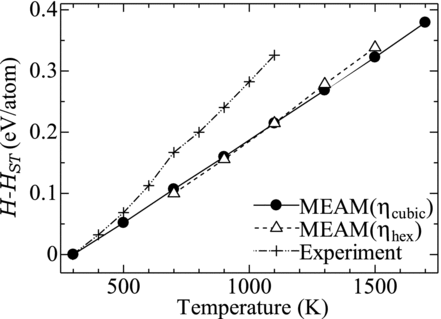
shows the predicted value of the enthalpy H−Hst where Hst is that at 298.15 K, compared with the experimental one [17]. The present MEAM model reproduces the experimental values for T < 500 K, however, it underestimates for the temperature higher than 500 K. For the temperature between 500 K and 700 K, the experimental result exhibits rapid increase (that is, large specific heat) as compared with those for the other temperatures. This is due to the increase in the specific heat around the Curie temperature of PuFe2, 633 K, which is not taken into account in the MEAM calculation. This underestimation of the enthalpy in the present MEAM model would be also responsible for the too high melting temperature of PuFe2 as described above.
In the same figure, the calculated enthalpy for η hex phase of PuFe2 is also plotted. Although η hex phase is observed in the temperature range between 1013–1293 K, the calculation was made for the broader temperature range, 700–1500 K. The values of H−Hst were calculated with Hst for the cubic phase. For T ≤ 1100 K the enthalpy for η hex is slightly lower than that of η cubic. Since the difference of the enthalpy of the two phases ΔH ≡ Hhex −Hcubic at the transition temperature (1013 K) is associated with the latent heat, ΔH should be positive. It is then known that the present model underestimates Hhex relative to Hcubic at T of 1100 K.
4.2. Simulation of contact of Pu and Fe
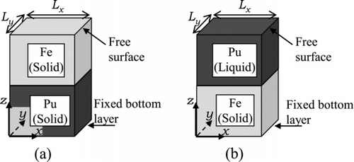
In order to explore the atomic diffusion on the interface between Pu and Fe, the simulations were performed by using a system illustrated in , in which pure, semi-infinite Fe slab and Pu slab (or liquid layer) were contacted with each other through an interface parallel to x-y plane.
Figure 4 System geometry for the simulation of contact of two materials. (a) Case 1 and (b) Case 2A–Case 4
The simulation conditions are summarized in Table . The simulation temperatures were set at 800 K, 1100 K, 1400 K and 1700 K. The surface orientation of the contacting surface of the solid was (110) or (100). For T = 1100 K (Case 2A and Case 2B), simulations were made for both (100) and (110) orientations of the contact surface of Fe. Periodic boundary condition was imposed on x and y directions for all the conditions.
Table 3 Simulation conditions for the simulation of contact
Case 1, in which the Pu atoms are also in solid phase, was performed to explore the eutectic point of Pu-Fe alloy observed for XPu = 90%. This eutectic reaction could be simulated by contacting Pu6Fe with Pu; however the contact of pure Pu and Fe is more relevant to the analyses for CDAs then examined. The system temperature in this case was below the melting point of Pu only by 113 K. The bottom atoms of the Pu slab put below the Fe slab (i.e. the atoms on the opposite surface to the Pu-Fe interface) were then constrained to the fixed points in order to avoid unexpected melting of the Pu slab.
For Case 2A–Case 4, the Fe slab was put below the liquid layer of Pu, and the bottom layer atoms of the Fe slab were fixed at constant positions to avoid deformation of the slab.
The cell sizes in x and y directions were kept constant throughout each simulation. The cell sizes for all the cases, except Case 1, were determined based on the equilibrated lattice size of Fe. For Case 1, it was done based on the lattice size of Pu. That is, the cell size Lx and Ly were determined as the lengths corresponding to 10 and 6 lattices of Pu crystal (a 0 = 0.3663 nm), respectively. The value of Lx does not match the longer side of the equilibrated lattice size of Fe (0.414 nm for (110) surface of body-centered cubic lattice), the Fe lattice was then distributed with reduced length of the longer side to 0.407 nm (98.2% of equilibrium size), which leads to the alignment of 9 lattices of Fe in the x direction of the cell.
The Fe slab and liquid layer (or slab) of Pu were separately equilibrated at the target temperature with zero pressure in the preliminary calculations. The simulations were then initiated by contacting the surfaces of the equilibrated Pu layer (or slab) and Fe slab.
Shown in are the instantaneous distributions of the atoms projected onto x-z plane at t = 2000 ps or 4000 ps. As shown in the figure, the Pu and Fe atoms penetrate into the bulk of the other metal. This indicates that the atomic diffusion with dissolution or melting progressed at the interface.
Figure 5 Distribution of atoms in the simulation of contact. Black and gray particles represent Pu and Fe atoms, respectively. (a) Case 1 (T = 800 K, t = 8000 ps), (b) Case 2A (T = 1100 K, t = 8000 ps), (c) Case 2B (T = 1100 K, t = 2000 ps), (d) Case 3 (T = 1400 K, t = 4000 ps) and (e) Case 4 (T = 1700 K, t = 2000 ps)
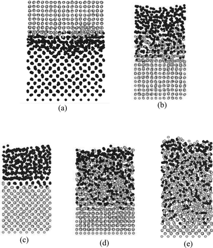
For Case 1, in which both the metals are in solid phase, the distributions of the atoms near the interface are disturbed, as seen in surface melting phenomena [Citation25], which is the phenomena wherein the melting occurred in the region molecularly close to the surface (or interface) even below the melting point. In the corresponding temperature (800 K), no surface melting was observed both for the Pu and Fe surfaces on their free surfaces before the contact. It can be thus concluded that the contact enhances the surface melting on the interface between them. This should have served as promotion of the mutual diffusion (namely, mutual dissolution) at the interface as if they are contacted in the liquid phases. Such surface melting is the essential mechanism for the initiation of the eutectic melting in which the two contacted metals melt below either of their melting temperatures [Citation10].
For Case 2A, Case 3 and Case 4, the Fe atoms diffused (dissolved) into the liquid Pu layer more prominently than the Pu atoms did into the solid Fe. The thickness of the mixing region, in which both Pu and Fe atoms coexist, spreads more rapidly than in Case 1. In the highest temperature case, Case 4, almost all the Pu and Fe atoms mixed with each other by 2000 ps.
In Case 2B, the Pu atoms adjacent to the interface formed clear coherent crystalline structure with Fe. Such ‘epitaxial’ crystallization can be seen when the lattice size in the solid state of the corresponding material [Citation26] or the number density of atoms [Citation27] is close to that of the other material. For the present case, epitaxial crystallization was developed for only one layer. Thus by taking into account only the distance between the neighboring atoms on the interface, the distance of the nearest neighbor atoms of Pu in β phase (0.297 nm) is close to the interval of the Fe atoms (equal to the lattice size of 0.290 nm). Then such solidification by the epitaxial crystallization is likely to be developed. This solidification of Pu at the interface prevented the diffusion across the interface. As a result, the Fe atoms diffused into Pu bulk only in early period (∼100 ps) before this epitaxial layer of Pu was developed. Such epitaxial crystallization was seen even when the potential parameters for Pu-Fe interaction were widely varied. No experimental observations, however, have been reported on such crystallization, thus further investigation should be performed for the clarification of this phenomenon.
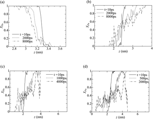
depicts the profiles of the atomic concentration of Pu, XPu , along z axis for all the cases except Case 2B. The distribution of XPu was calculated as the number density concentration of Pu atoms, in each layer with a thickness of 0.025 nm parallel to x-y plane over the whole cross section of the simulation cell. The values presented in the figure are those averaged for 10 ps around the corresponding time. The magnitude of the gradient of XPu in the mixing region (0 < XPu < 1) decreases with time. This indicates that the diffusion progresses with time. The decreasing rate of the gradient apparently depends on the temperature. That is, the gradient of XPu in Case 4 (T = 1700 K, the highest temperature case) decays more prominently than those for the lower temperatures.
Figure 6 Profiles of the atomic concentration of Pu (XPu ). (a) Case 1, (b) Case 2A, (c) Case 3 and (d) Case 4
The time evolution of the diffusion can be clearly represented by the thickness of the mixing region, η 10-90, where 0.1 < XPu < 0.9. The values of η 10-90, as shown in , increased with time. The values of η 10-90 for higher temperatures increase more rapidly than those for the lower temperatures. For all the cases the increasing rate of η 10-90 (i.e. dη 10-90/dt) gradually declined with increase in time; however for t > 2000 ps in Case 3 and t > 1000 ps in Case 4, dη 10-90/dt fell rapidly to zero. These rapid falls should be caused as the result that the concentration of Fe atoms reached the saturation concentration in liquid Pu for Case 3 and that all the Fe atoms dissolved and diffused over the whole region of liquid Pu for Case 4.
Figure 7 The time evolution of η 10-90. Dashed lines represent fitting by Equation (Equation16)
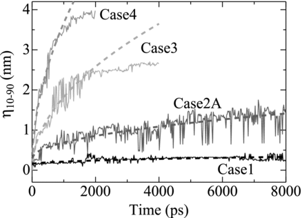
For the other period, the processes which contribute to the variation in η 10-90 with time should be (1) the dissolution process of the Fe atoms into Pu and (2) the diffusive motion of the atoms. By assuming that the diffusive motion is more responsible to η 10-90 than the dissolution process, the evolution of η 10-90 is expected to follow the parabolic rule [Citation28], that is,
Equation (Equation16) was fitted to all the data of η 10-90 for each case shown in Figure , except t > 2000 ps for Case 3 and t > 1000 ps for Case 4. As shown in the figure by dashed lines, the evolution of η 10-90 was well fitted by Equation (Equation16) for all the cases. This indicates that the rates of the dissolution or melting at the solid-liquid interface were dominated by the diffusive motion of the Pu and Fe atoms. This result also implies that the decrease in the increment rate of η 10-90 with time was primarily owing to the decrease in the magnitude of the spatial gradient of XPu , that is, ∂XPu /∂z.
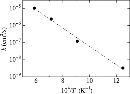
In , the obtained values of k are plotted versus inverse of the temperature. As shown in the figure, the logarithm of k linearly decreases with T −1, indicating that k obeys the Arrhenius form. It is worth noting that k for Case 1 (104/T = 12.5 K−1) also meets the fitting line drawn in the figure, though the initial configuration in Case 1 is the coalescence of two solid phases. This indicates that, in Case 1, the melting on the solid-solid interface was also dominated by the diffusion in the liquid phase. For this indication it is required that the region of the surface melting should have expanded before the atoms of the other metal diffused to the point where liquefaction took place. This is consistent with the observation in Figure that the surface melting occurred and the diffusion takes place in the melting region. However for this case the evolution rate of surface melting and diffusion is quite low, so further simulation should be needed to estimate the phenomenon in the macroscopic practical system.
Figure 8 Temperature dependence of k in Equation (Equation16). Black circles are MD results, and dashed line is the best fit
4.3. Simulation of contact of PuFe2 and Fe
Pu-Fe system has the other eutectic temperature around XPu ≈ 0.2 as shown in Figure . This eutectic point was examined by the simulation of the contact of PuFe2 compound and pure Fe slabs. The simulation procedures were similar to that described in Section 4.2. The slab of PuFe2 was put above the Fe slab with the bottom atoms constrained at the fixed positions. The top surface of PuFe2 slab was free surface. The surface of Fe slab was (100) of face-centered cubic (f.c.c.) lattice.
The simulations were performed for two temperature cases of 1500 K and 1600 K, both of which were lower than the melting temperature of PuFe2 simulated by the present model (approx 1700 K). The lengths of the cell, Lx and Ly , are 2.9128 nm and 2.9128 nm for T = 1500 K and 2.9232 nm and 2.9232 nm for T = 1600 K, both of them corresponding to 4 lattices of PuFe2 crystal in x and y directions, respectively. The consequent deviation of the length of the distributed Fe lattice in the corresponding cell sizes from that of equilibrated Fe lattice was below 0.8%. The slabs of Fe and PuFe2 were separately equilibrated in the preliminary calculations with the positions of the atoms in the top layer of PuFe2 slab and in the bottom layer of Fe being fixed.
depicts the instantaneous distributions of the atoms projected onto x-z plane at t = 0 ps and 3000 ps. As seen in Figure (T = 1600 K), surface melting was observed at the surface of Fe, which occurred before the contact with the PuFe2 slab. On the other hand the surface of PuFe2 did not melt at t = 0 ps. The distribution of ρN for 1500 K was quite similar to Figure .
Figure 9 Distribution of atoms projected onto x-z plane in the simulation of contact of PuFe2 and Fe. Black and gray particles represent Pu and Fe atoms, respectively. (a) 0 ps (T = 1600 K), (b1) 3000 ps (T = 1500 K) and (b2) 3000 ps (T = 1600 K)
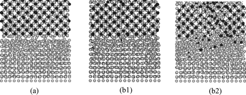
At t = 3000 ps, for T = 1500 K (Figure ), a few Pu atoms which were contained in PuFe2 at the initial distribution moved into the Fe slab, however the crystalline structure of Fe slab was still maintained. On the other hand, for T = 1600 K (Figure ), the crystalline structure of Fe near the interface became unclear and more Pu atoms diffused into the Fe slabs. This indicates that the present model reproduced the existence of the eutectic melting point between Fe and PuFe2 around 1600 K.
In the profiles of the number density ρN at 100 ps (Figure for T = 1600 K) and at 3000 ps (Figures for T = 1500 K and 1600 K, respectively) are shown. The initial position of the interface between the Fe and PuFe2 slabs was z ≈ 2 nm. In all the figures, periodic changes in ρN can be seen, which represent the layered distribution of the atoms. This layer structure should be mainly associated with the crystalline structure of Fe and PuFe2. For t = 100 ps (Figure ), although surface melting of Fe should advance near the interface, the clear layered distribution of the Fe atoms is maintained.
Figure 10 Distribution of the number density of the atoms, ρN . (a)t = 100 ps (T = 1600 K), (b1) t = 3000 ps (T = 1500 K) and (b2) t = 3000 ps (T = 1600 K)
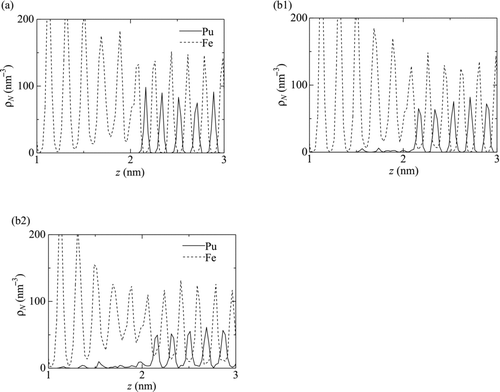
At t = 3000 ps, the distribution was almost unchanged from that at t = 100 ps for T = 1500 K (Figure ) except for a few Pu atoms which moved to z ≈ 1.5 nm in the Fe slab. While, for T = 1600 K (Figure ), ρNPu in 1.1 nm < z < 2.2 nm increases up to 10 nm−3, indicating the diffusion of the Pu atoms into the Fe slab. More importantly, for 1.3 nm < z < 3 nm the amplitude of the variation of ρNFe in this area is remarkably decreased from that in the other area. This moderation of the layered distribution indicates that the slabs in this area were melted into liquid phase and the crystalline structure was disintegrated.
Such disintegration of the structure can be also quantified with the S factor defined as [Citation29]
Figure 11 Distribution of S factor 〈Sm 2〉 for Fe defined in Equation (Equation17). (a) T = 1500 K and (b) T = 1600 K
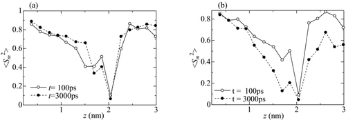
For T = 1500 K, as shown in Figure , the distribution of 〈Sm 2〉 is almost unchanged from t = 100 ps until 3000 ps. This means that the crystalline structure was maintained except in the vicinity of the interface (1.7 nm < z < 2.1 nm) where surface melting on the surface of the Fe slab occurred before the their contact. For T = 1600 K, as shown in Figure , 〈Sm 2〉 in 1.3 nm < z < 3 nm at t = 3000 ps remarkably decreased from that at t = 100 ps, indicating that the lattices in this region disintegrated (melted) and the atoms behaved as liquid phase. This estimated range of the melting region agrees with that in which the layered structure presented in Figure is moderated.
5. Conclusion
Atomic diffusion across the interface between Pu and Fe was investigated in the framework of MEAM. The applied potential parameters for Pu and Fe were those proposed by Baskes [Citation5] and Lee et al. [Citation6], respectively. The potential parameters for Pu-Fe interaction were developed so as to reproduce the material properties of the two compounds, PuFe2 and Pu6Fe, measured in the experiments or calculated with the first principle calculations by using VASP and WIEN2k codes. The material properties of the compounds predicted by the developed potential are in good agreement with the experimental data.
The dissolution or melting at the interface between pure Pu and Fe was simulated by contacting semi-infinite slab of Fe with liquid layer of Pu or slab of Pu. Dissolution was observed for all the tested temperature conditions from 800 K up to 1700 K. For the simulation with T = 800 K, in which solid Pu and Fe slabs were contacted with each other, the surface melting occurred at the interface, which enhanced the diffusion at the interface. The time evolution of the thickness of the mixing region, in which 0.1 < XPu < 0.9, strongly depended on the temperature, and was found to be dominated by the atomic diffusion in the liquid phase even in the simulation for the contact of the two solids.
The melting at the interface was also observed on the interface between Fe and PuFe2 in solid phase at the temperature approximately 100 K below the melting temperature of PuFe2 obtained based on the present model. This indicates that the model reproduces the existence of the eutectic point between Fe and PuFe2.
Acknowledgements
A part of this study was carried out within the task ‘R&D of the Next Generation Safety Analysis Methods for Fast Reactors with New Computational Science and Technology’ entrusted from the Ministry of Education, Culture, Sports, Science and Technology of Japan.
Notes
b.c.c: body-centered cubic, f.c.c.: face-centered cubic.
References
- Daw , M S and Baskes , M I . 1984 . Embedded-atom method: derivation and application to impurities, surfaces, and other defects in metals . Phys Rev B , 29 : 6443 – 6453 . doi: 10.1103/PhysRevB.29.6443
- Baskes , M I . 1992 . Modified embedded-atom potentials for cubic materials and impurities . Phys Rev B , 46 : 2727 – 2742 . doi: 10.1103/PhysRevB.46.2727
- Baskes , M I . 1997 . Determination of modified embedded atom method parameters for nickel . Mater Chem Phys. , 50 : 152 – 158 . doi: 10.1016/S0254-0584(97)80252-0
- Baskes , M I , Chen , S P and Cherne , F J . 2002 . Atomistic model of gallium . Phys Rev B , 66 104107-1-104107-9 doi: 10.1103/PhysRevB.66.104107
- Baskes , M I . 2000 . Atomistic model of plutonium . Phys Rev B. , 62 : 15532 – 15537 . doi: 10.1103/PhysRevB.62.15532
- Lee , B-J , Baskes , M I , Kim , H and Cho , Y K . 2001 . Second nearest-neighbor modified embedded atom method potentials for bcc transition metals . Phys Rev B. , 64 : 184102-1-184102-11 doi: 10.1103/PhysRevB.64.184102
- Lee , B-J . 2007 . A modified embedded atom method interatomic potential for silicon . Comp Coupl Phase Diagrams Thermochem , 31 : 95 – 104 . doi: 10.1016/j.calphad.2006.10.002
- Webb , E B III , Grest , G S , Heine , D R and Hoyt , J J . 2005 . Dissolutive wetting of Ag on Cu: a molecular dynamics simulation study . Acta Meter. , 53 : 3163 – 3177 . doi: 10.1016/j.actamat.2005.03.021
- Chen , S D , Soh , A K and Ke , F J . 2005 . Molecular dynamics modeling of diffusion bonding . Scripta Mater , 52 : 1135 – 1140 . doi: 10.1016/j.scriptamat.2005.02.004
- Ito , T . 2009 . Molecular dynamics study on melting phenomena in Cu-Ag eutectic system . J Power Energy Syst. , 3 : 261 – 271 . doi: 10.1299/jpes.3.261
- Lee , B J . 2006 . A modified embedded-atom method interatomic potential for the Fe-C system . Acta Mater. , 54 : 701 – 711 . doi: 10.1016/j.actamat.2005.09.034
- Lee , B J , Wirth , B D , Shim , J-H , Kwon , J , Kwon , S C and Hong , J-H . 2005 . Modified embedded-atom method interatomic potential for the Fe-Cu alloy systems and cascade simulations on pure Fe and Fe-Cu alloys . Phys Rev B. , 71 : 184205-1-184205-15 doi: 10.1103/PhysRevB.71.184205
- Baskes , M I , Lawson , A C and Valone , S M . 2005 . Lattice vibrations in δ-plutonium: molecular dynamics calculation . Phys Rev B. , 72 014129-1-014129-7 doi: 10.1103/PhysRevB.72.014129
- Baskes , M I , Muralidharan , K , Stan , M , Valone , S M and Cherne , F J . 2003 . Using the modified embedded-atom method to calculate the properties of Pu-Ga alloys . JOM the Member J TMS , 55 : 41 – 50 . doi: 10.1007/s11837-003-0029-7
- 1992 . ASM handbook volume 3 - alloy phase diagrams , 200 USA : The Materials Information Society .
- Hecker , S S . 2000 . Plutonium and its alloys-from atoms to microstructure . Los Alamos Science , 26 : 291 – 335 .
- Campbell , G M . 1971 . The thermodynamic properties of PuFe2 from EMF measurements . Los Alamos Sci Lab Report , LA-4638 : 1 – 4 .
- Akhachinkii , V V . 1963 . Symposium on the thermodynamics of nuclear materials . Atom Energy , 15 : 1082 – 1089 . doi: 10.1007/BF01119559
- Mardon , P G , Haines , H R , Pearce , J H and Waldron , M B . 1957 . The plutonium-iron system . J Inst Metals , 86 : 166 – 171 .
- http://cms.mpi.univie.ac.at/vasp/
- http://www.wien2k.at/
- Itié , J P , Staun Olsen , J , Gerward , L , Benedict , U and Spirlet , J C . 1986 . High pressure X-ray diffraction on UX2 compounds . Physica , 139 & 140B : 330 – 332 .
- Nosé , S . 1984 . A unified formulation of the constant temperature molecular dynamics methods . J Chem Phys. , 81 : 511 – 519 . doi: 10.1063/1.447334
- Berendsen , H JC , Postma , J PM , van Gunsteren , W F , DiNola , A and Haak , J R . 1984 . Molecular dynamics with coupling to an external bath . J Chem Phys , 81 : 3684 – 3690 . doi: 10.1063/1.448118
- Tartaglino , U and Tosatti , E . 2003 . Strain effects at solid surfaces near the melting point . Surf Sci. , 532–535 : 623 – 627 . doi: 10.1016/S0039-6028(03)00470-9
- Thompson , P A and Robbins , M O . 1990 . Shear flow near solids: epitaxial order and flow boundary conditions . Phys Rev A. , 41 : 6830 – 6837 . doi: 10.1103/PhysRevA.41.6830
- Ounadjela , K , Vennegues , P , Henry , Y , Michel , A , Pierronbohnes , V and Arabski , J . 1994 . Structural-changes in metastable epitaxial Co/Mn superlattices . Phys Rev B. , 49 : 8561 – 8573 . doi: 10.1103/PhysRevB.49.8561
- Oberhauser , S , Strobl , C h , Schreiber , G , Wuestefeld , C h and Rafaja , D . 2010 . Formation of periodic patterns in the (Ni,W)/Al diffusion couples . Surf Coat Tech. , 204 : 2307 – 2315 . doi: 10.1016/j.surfcoat.2009.12.027
- Thomas , J A and McGaugheya , A JH . 2007 . Effect of surface wettability on liquid density, structure, and diffusion near a solid surface . J Chem Phys. , 126 : 034707-1-034707-9 doi: 10.1063/1.2424934
