Abstract
A countercurrent centrifugal extractor with an inner rotor and a stationary outer wall has been developed in which aqueous and organic phases flow countercurrently between two walls. The formation of stable Taylor vortices in the gap makes multistage extraction possible. Understanding the relation between flow state and percent extraction is important for achieving a greater number of theoretical stages in a single extractor. Hence, oil–water countercurrent flow is measured by ultrasonic velocity profiling, without disturbing the flow, under different feed rates of solutions and rotating speeds of the inner rotor. In continuous extraction tests, Zn2+ in nitric acid and di-(2-ethylhexyl)-phosphoric acid diluted by n-dodecane are used. Measurement results are verified by numerical simulation. Finally, a correlation chart of flow patterns and operating conditions is prepared.
1. Introduction
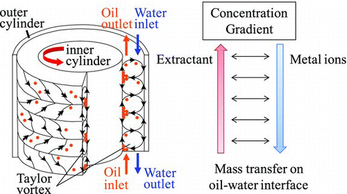
Many types of extraction reactors have been developed. Practical reactors such as mixer-settlers and pulsed column reactors are suitable for mass production, each with its own set of advantages and disadvantages [Citation1]. Such reactors are used in diverse areas, such as the mineral industry and spent nuclear fuel reprocessing [Citation2]. The extraction and separation of nuclei are becoming increasingly important. For example, separation of long-lived and poisonous nuclides from high-level liquid waste (HLLW) is effective in reducing the environmental load. Removing heat-emitting nuclei such as Cs-137 or Sr-90 from HLLW significantly reduces the amount of glass needed for final disposal. Verification tests using actual HLLW with continuously connected small centrifugal extractors have been performed [Citation3, Citation4]. The recovery of precious metals and reusable materials such as lanthanides and actinides from nuclear waste is also important, owing to their scarcity in natural ores. Ozawa et al. have proposed a strategic nuclear fuel cycle called the ORIENT cycle for production of useful nuclei from nuclear waste and nuclear rare metals (NRMs) [Citation5, Citation6]. The fission products of U-235 include more than 40 elements and 400 nuclides, and are especially rich in Ru, Rh, Pd, Tc, Mo, Cs, Sr, and lanthanides. However, conventional mixer-settlers and pulsed column reactors are not suitable for extracting these products because the ratio of NRMs in spent nuclear fuel is low, and a considerable amount of secondary radioactive waste is produced. Therefore, a small but high-performance centrifugal extractor is necessary for this particular task. Countercurrent centrifugal extractors that form the Taylor–Couette flow allow for effective dispersion of oil, formation of axial concentration gradients, and an adequate amount of oil holdup, thus improving extraction ratios as compared with single extractors, making multistage extraction possible. A series of Taylor vortices is formed ().
Mathematicians, physicists, chemists, and biologists have been studying Taylor–Couette flows for years, and have performed numerous experimental and computational studies. For example, Sandesh et al. studied the phenomenon both experimentally and computationally [Citation7, Citation8], analyzing the formation and stability of Taylor vortices in single-phase water flow and comparing the results of various measurement techniques.
Various methods have been applied in studying Taylor–Couette flows, such as particle image velocimetry (PIV), particle tracking velocimetry (PTV), laser-induced fluorescence (LIF), and laser Doppler velocimetry (LDV). When applying PIV, velocity distributions are measured by detecting differences in tracer particle positions between two images at different times. PTV is similar to PIV, measuring streamlines by tracking tracer particles, usually with LIF. Tracer particles are not suited to measuring oil–water flow, however, because the particles may affect the oil–water interface, changing the dispersion behavior.
Compared with single-phase flows, two-phase Taylor–Couette flows have been the target of fewer studies, owing to their complexity. In the case of immiscible two-phase flows, it is important to understand the interfacial behavior, the stability of the two phases, and the mass transport at the interface [Citation9–Citation11]. Mayur et al. attempted to use computational fluid dynamics (CFD) calculations to measure fluid flows by the PIV and PLIF methods [Citation12, Citation13]. In the LIF method, oil holdup can be evaluated by adding a fluorescent material into the organic phase and illuminating the material with a laser to induce flashing of the organic phase. Mayur et al. also changed material properties such as density difference, interfacial tension, and geometric structure to observe the effects of these changes. Monitoring the behavior of the oil–water interface is difficult due to low spatial resolution. In LDV, the flow state can be examined in detail by applying a strong laser beam, but the spatial resolution is still too low.
Currently, ultrasonic velocity profiling (UVP) is used for examining the velocity distribution of flows without disturbing the flow itself. Takeda et al. developed an application for measuring flows by using an ultrasonic Doppler shift detector [Citation14–Citation16]. The frequency of sound changes due to the Doppler shift, and the size of the vortices and their residence times are calculated from the axial velocity (in fact, the Doppler frequency is calculated using a certain correlation equation). The measurement setup consists of a transducer, PC, and pulse generator. The transducer emits ultrasonic waves and receives their reflections, allowing for flow measurements of regions reachable by the ultrasound waves, even if the fluid is completely opaque. Researchers have applied the UVP method to clarify the flow of single-phase structures of not only water flows, but also magnetic flows [Citation17–Citation19]. There has also been research on two-phase flow measurement using UVP, but most studies have examined bubbly flows [Citation20–Citation25], and there are few measurement studies on oil–water multiphase flows [Citation26]. Although UVP measurements are applicable in many cases, certain difficulties and problems with this method are yet to be overcome. For example, ultrasound attenuates rapidly, and as a result, measuring velocities far from the transducer is difficult, especially for a narrow fluid region. In this study, numerical simulation is applied to confirm the validity of UVP measurements in the narrow fluid region of our extractor, and the relation between flow patterns obtained by UVP measurement and percent extraction is examined for the purpose of achieving extraction with a greater number of stages.
2. Experimental setup and conditions
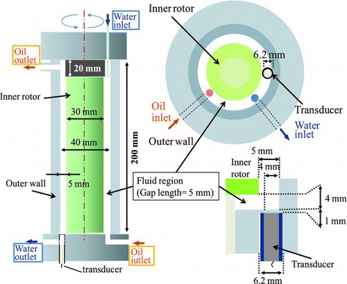
shows the experimental setup. An aqueous phase is injected from above through an SUS pipe with a diameter of 1 mm, and an organic phase is injected from below through a hole with a diameter of 3 mm. The values of geometric and dimensionless parameters are listed in . The organic phase rises and the aqueous phase settles according to the difference in their respective specific gravities. The rotating inner rotor is made of Teflon, and its radius D i is 15 mm. The stationary outer wall is made of acrylic, and its radius D o is 20 mm. Thus, the gap d between the inner rotor and the outer wall is 5 mm. A stationary cylinder (referred to as the skirt) is installed at the top of the inner rotor to promote the settling of oil and water. A transducer that emits ultrasonic waves and receives reflected waves is installed beneath the gap between the rotors. The transducer is installed closer to the outer wall than to the inner rotor in order to measure the velocity of the outer half of the vortices in the gap (Figure ). In the experiments, the feed rates of aqueous and organic phases are varied between 3 mL/min and 20 mL/min, and the rotating speed of the inner rotor is varied between 400 rpm and 1500 rpm. The parameters of the experimental conditions are converted to dimensionless parameters to make a comparison with the values obtained in other studies and to clarify the flow states or patterns. The values of the axial Reynolds number Rez , azimuthal Reynolds number Reθ , and capillary number Ca are calculated and listed in Table . Here, Rez and Reθ are calculated using the properties of the aqueous (continuous) phase, and Ca is calculated using the properties of the organic (dispersed) phase. Such dimensionless numbers enable comparisons between different geometries and operating conditions. To calculate the values of the dimensionless parameters in a liquid–liquid two-phase flow in accordance with chemical extraction, we must consider that the properties of aqueous and organic phases are sensitive to time and position in the extractor. For example, surface tension decreases by increasing the concentration of the metal–DEHPA [di-(2-ethylhexyl) phosphoric acid] complex [Citation27, Citation28]. Therefore, Ca is calculated using rotating speeds of 100–1500 rpm and a surface tension of 5–25 mN/m to account for the surface activation effect. However, the correct evaluation of dimensionless parameters is difficult, and thus more effective ways for their evaluation are sought.
Table 1 Geometric parameters, operating conditions and dimensionless parameters
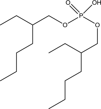
From the long history of research on Taylor vortices, it is currently well known that various types and patterns of vortices are induced in the annular fluid region between two rotating cylinders. The patterns of Taylor vortices depend on factors such as the aspect ratio of the fluid region, the ratio of the radii of the two cylinders, whether there is a free surface or fixed end, geometry, and the properties of the working fluid under the operating conditions. From the viewpoint of a liquid–liquid countercurrent centrifugal extractor, the effects of geometry, axial flow rates [Citation29, Citation30], and the ratio of organic and aqueous phases [Citation13,Citation31] are particularly important. Although the effect of the edge is considered to be substantial regardless of the aspect ratio, a number of studies have been conducted with aspect ratios higher than 20 to minimize the edge effect. In contrast, aspect ratios lower than about 15 are chosen when investigating the edge effect [Citation32]. Based on previous studies, the impact of the operating conditions in our extractor on the mode divarication of induced Taylor vortices in the continuous phase is considered small. The aspect ratio of our extractor is about 40, and the radius ratio is 0.75. Hence, although the continuous aqueous phase in our extractor is classified as a turbulent vortex under these conditions, at the same time, the pattern of the dispersed organic phase may differ depending on the presence of a secondary organic phase. Furthermore, in the region where the flow patterns of the continuous phase are prominent, the dispersion of the organic phase is insufficient, and the interfacial area is too small for multistage theoretical extraction. Mass transport on the oil–water interface is determined by chemical equilibrium, and the formation of a concentration gradient in the extractor is more important than the effect of mode divarication of the continuous phase. During the operation, one solution is mixed (entrained) into the other solution through outlet holes when the flow rate is too high, in which case, the flow resembles a plug flow. Even if the flow undergoes transition to emulsion flow under some operating conditions, smaller droplets congregate in both the oil and the water outlet tubes, which enables proper sampling for quantitative analysis. This must be prevented in order to achieve higher percent extraction and a greater number of extraction stages. The aqueous phase contains 1 mM Zn2+ in nitric acid. The pH is 2.5, and the ion intensity is 0.01 due to added sodium nitrate. The organic phase consists of 10 mM DEHPA in n-dodecane. shows the structure of DEHPA. The concentration of Zn2+ in the aqueous phase is measured with an intensity-coupled plasma atomic emission spectrometer (ICPE-9000; Shimadzu, Kyoto, Japan). The extraction performance is determined by the formation of the following Zn2+–extractant complex:
3. Conditions for UVP measurements
The axial velocity far from the transducer cannot be measured by UVP because of the strong absorbance of ultrasonic waves in the organic and aqueous phases in the narrow fluid region. To measure the velocity in positions farther from the transducer by UVP, the transducer was optimized in terms of the diameter and the material of the piezoelectric element for emitting and receiving ultrasound and the measurement conditions such as sound frequency and sampling frequency for calculation of the velocity profile. The conditions for UVP measurement are listed in . Generally, a lower frequency of emitted sound results in greater penetration depth, but this also results in lower spatial resolution. Ultrasound is readily absorbed by the fluid, which makes it difficult to obtain measurements from farther locations. Therefore, a transducer with a different diameter was specially developed to obtain measurements from locations farther from the bottom. Initially, a transducer with a smaller diameter was installed, but the ultrasonic waves it emitted could not reach locations far from the bottom. Subsequently, a transducer with an outer radius of 6 mm and an effective diameter of the microphone and the receiver of 4 mm was specially developed, and the frequency of ultrasonic waves was set to 8 MHz. As a result, we successfully expanded the distance in the narrow gap measurable by UVP to nearly 90 mm.
Table 2 Conditions of UVP measurements
4. Conditions and settings for numerical simulation
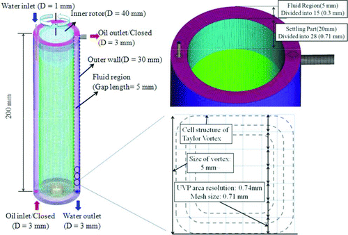
To confirm the validity of the measurement results obtained by UVP, numerical calculations were performed using the commercial CFD software ANSYS FLUENT 13.0. A model with the same geometry as the actual extractor [with inner structures such as the skirt and the water injection pipe (1 mm in diameter)] was created by using 3D-CAD, and a fine hexagonal mesh was generated using the commercial meshing software ANSYS ICEM CFD (). The grid size of the created mesh was nearly the same as the spatial resolution of UVP measurements (0.74 mm), and the quality of the created mesh was enhanced by using a smoothing algorithm available in the meshing software. The calculation conditions and settings are presented in . Sensitivity analysis was conducted as a preliminary calculation to find the optimal calculation conditions and settings, such as the turbulence model, calculation scheme, and discretization methods for each term. Numerous models were prepared with ANSYS FLUENT 13.0 and tested to resolve the Taylor–Cuette flow. Finally, the Reynolds stress model (RSM) was selected as a turbulent model, which has been reported as suitable for resolving Taylor–Cuette flows [Citation7]. The time step for transient calculation was set to 0.001 s, which is considerably shorter than the time resolution of UVP measurements (0.038 s). The Navier–Stokes equations were solved by a pressure-based solver, and unsteady formulation and momentum are discretized by a first-order implicit scheme and a second-order upwind scheme, respectively.
Table 3 Numerical simulation conditions
5. Results and discussion
5.1. Visualization of single-phase water flow
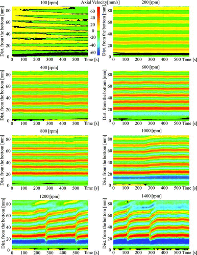
shows the results of using UVP to measure single-phase water flow. Blue regions indicate upward flow, while red and yellow regions indicate downward flow. This figure shows a stripe pattern of the velocity distribution with time variation, indicating stable formation of Taylor vortices. At a rotating speed of 100 rpm, vortices were unstable. Stable vortices arose when the rotating speed was increased to 200 rpm. Furthermore, when the rotating speed exceeded 1000 rpm, an ascending flow pattern was observed. The velocity in vertical direction also increased together with the rotating speed, and when the rotating speed exceeded 1200 rpm, the number of annular vortices decreased and an upward stream was observed. This results from the fact that the input agitating power is too high to be consumed by a series of smaller Taylor vortices. Larger vortices can efficiently consume more agitating power than smaller vortices with higher velocity in vertical direction. At high rotating speeds, the flow became unsteady, and a wavy flow was observed even when the top of the extractor was hermetically sealed. These results suggest that operating conditions are important for stable and effective extraction using this type of small contactor.
5.2. Verification of UVP measurements and numerical simulation
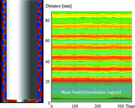
To verify the results of UVP measurements, a 3D transient calculation of single-phase water flow in the centrifugal extractor was conducted. shows the simulation results (2D contours) for single-phase water flow in the extractor. Similarly to Figure , red regions indicate downward flows and blue regions indicate upward flows. In the results, blue and red areas coupled side by side indicate a single annular Taylor vortex. Hence, the results show that the size of each vortex is approximately the same as the gap width (5 mm). This agrees with the fluid dynamics theory and the results obtained in the extraction tests, confirming that the flow of Taylor vortices was successfully simulated under the specified calculation conditions. shows the results of the numerical simulation and the velocity distribution measured by UVP. These data are in agreement, with the exception of data for locations close to the transducer installed at the bottom. This discrepancy is due to the difficulty in measuring flow velocity by UVP in regions close to the transducer, where ultrasound emitted from the transducer is unstable and nonuniform. This region of instability is known as the near field, and its extent can be estimated by using the following equation proposed in a UVP manual [Citation33, Citation34]:
5.3. Visualization of oil–water countercurrent flow by UVP and the relation between flow pattern and percent extraction
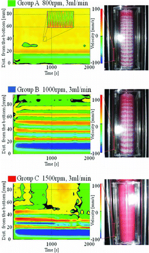
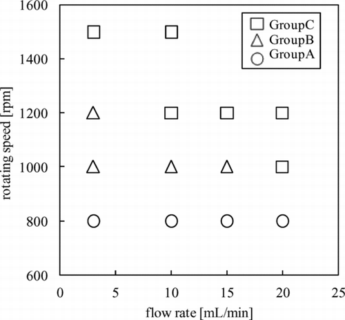
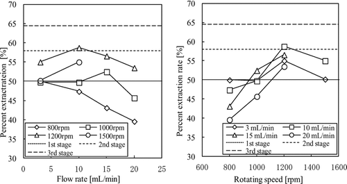
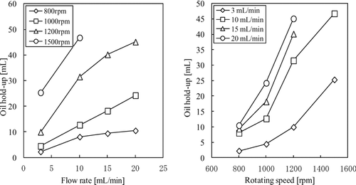
Multiphase oil–water countercurrent flows with different oil–water feed rates (3–20 mL/min) and different rotating speeds of the inner rotor (100–1500 rpm) were measured by UVP, and extraction experiments were performed simultaneously. Owing to the strong absorbability of ultrasonic waves by the dispersed organic phase, measurement and visualization are more difficult than in the case of single-phase water flow. However, even if the flow is opaque, its velocity can be measured by UVP due to the utilization of ultrasound. Based on the dimensionless parameters in the current experimental conditions, the flow pattern of the continuous phase was classified as a turbulent vortex. UVP measurements reveal only the behavior of a dispersed phase (organic phase). presents a map of the relation between the patterns of oil–water flow and percent extraction. To discuss the relation between oil–water countercurrent flow and percent extraction, the flow patterns of the dispersed phase as obtained by UVP measurements are classified as follows: (A) spiral flow, (B) ring flow, and (C) ring flow with emulsion. When the rotating speed is 800 rpm and the feed rate of solution is 3–20 mL/min, stable flow is observed. The organic phase is not completely dispersed, and a certain portion of the organic phase adheres to the rotating inner wall. In this case, the dispersed phase reflects ultrasound, and a regularly ascending pattern is observed. We classify this flow pattern as spiral flow. At a rotating speed of 1200 rpm and a feed rate of organic phase of 3 mL/min, and at a rotating speed of 1000 rpm and a feed rate of 3–15 mL/min, a stripe pattern is acquired in the UVP measurement. This indicates that the continuous aqueous phase is stable and the dispersed organic phase follows the Taylor vortices. We classify this flow pattern as ring flow. In group (C), after 30 min, the flow undergoes transition to emulsion flow in all regions of the fluid in the extractor from the beginning of the extraction operation. Correspondingly, the region where velocity measurements are difficult by the UVP method moves away from the upper region. We classify this pattern of flow as ring flow with emulsion. shows the effects of flow rate and rotating speed on percent extraction. At lower rotating speeds, the percent extraction becomes lower because the dispersion of the organic phase is insufficient. At higher rotating speeds, the percent extraction increases due to the effective dispersion of the organic phase, reaching extremely high values at high speeds. From the viewpoint of higher percent extraction, group (A) is not favorable due to its weak agitation capability. In group (C), the intensity of Taylor vortices is sufficiently strong and the axial flow rate is high, and as a result, it is difficult for droplets of the organic phase to pass through the toroidal structure of each of the vortices in emulsion flow, in which case, stable contact between organic and aqueous phases in the narrow gap becomes impossible. Therefore, the excess amount of the organic phase ascends, resulting in an upward flow near the static outer wall. Consequently, the axial concentration gradient is deformed, and percent extraction decreases. Furthermore, the results shown in Figure suggest that there are optimal operating conditions for higher extraction performance. Generally, higher rotating speeds with higher axial flow rates improve extraction performance, but when the rotating speed exceeds 1200 rpm and the axial flow rate exceeds 10 mL/min, the percent extraction decreases due to the disrupted stability of the oil–water interface. Further, entrainment of the aqueous phase into the organic phase occurs, which presents operational difficulties in commercial applications. Oil holdup is also measured based on the cumulative amount of the organic phase in the extractor after the extraction operation. show the relations between the oil holdup and the rotating speed of the inner rotor (panel on the left), and between the oil holdup and the axial flow rate (panel on the right). Oil holdup increases steadily by increasing the rotating speed and the axial flow rate. The percent extraction increases with increasing rotating speed and feed rate. However, the percent extraction decreases when the rotating speed exceeds 1200 rpm, due to entrainment. A comparison between the flow map and the percent extraction suggests that higher flow rates and rotating speeds (greater agitating power) with a stable series of Taylor vortices in the absence of entrainment results in higher percent extraction and a greater number of theoretical stages. Therefore, applying more effective ways of settling oil and water, even under conditions of high axial flow rates and inner rotor rotating speeds, is expected to improve extraction.
6. Conclusions
The following are the conclusions derived from this study:
| 1. | Oil–water countercurrent flow was visualized by the UVP method with optimized transducer and measurement conditions in an annular and narrow fluid region (5 mm in width), and different flow patterns were observed in both single-phase water flow and multiphase oil–water flow. | ||||
| 2. | UVP measurements in an annular and narrow fluid region (5 mm in width) were verified by comparison with the results of numerical simulations, and the sizes of vortices were found to be consistent. | ||||
| 3. | The relation between flow states of the organic phase and percent extraction was clarified, and correlation charts were prepared. Results suggest that higher flow rates and rotating speeds with a stable series of Taylor vortices (without entrainment) are suitable for achieving higher percent extraction and a greater number of theoretical stages. | ||||
Acknowledgements
This research was supported by Grants-in-Aid for Scientific Research from the Japan Society for the Promotion of Science. Instruments for UVP measurements were provided by H. Kikura, Associate Professor at the Solution Research Institute, Tokyo Institute of Technology. The three-dimensional mesh was initially created by H. Ohki and M. Tanaka et al. at the Japan Atomic Energy Agency, Oarai, Japan.
References
- Vancas , M F . 2003 . Pulsed column and mixer-settler applications in solvent extraction . JOM-J Min Met Mat S. , 55 : A43 – A45 . doi: 10.1007/s11837-003-0124-9
- Kishbaugh , A A . 2000 . “ Development and performance of centrifugal mixer-settlers in the reprocessing of nuclear fuel ” . In Proceedings of the Symposium May 17, 2000: Savannah River Site 50th Anniversary – 50 Years of Excellence in Science and Engineering at the Savannah River Site (WSRC-MS-2000-00061 , Edited by: Reinig , B , Springer , F , Phillips , A and Damiano , C . Washington , DC : US Department of Energy . May 17; Savannah River Site, Aiken (NC)
- Law , J D , Brewer , K N , Herbst , R S , Todd , T A and Wood , D J . 1999 . Development and demonstration of solvent extraction process for the separation of radionuclides from acidic radioactive waste . Waste Manage. , 19 : 27 – 37 . doi: 10.1016/S0956-053X(98)00120-2
- Law , J D , Herbst , R S and Todd , T A . 1999 . “ Idaho National Engineering and Environmental Laboratory High Level Waste Program ” . In Demonstration of the UNEX process for the simultaneous separation of cesium, strontium, and the actinides from actual INEEL tank waste (INEEL/EXT-99-00954) , Washington , DC : US Department of Energy .
- Ozawa , M , Ohtaki , A and Asakura , T . 2010 . Rare metals in nuclear spent fuels, their separation and utilization strategy . INCS News , 7 : 17 – 26 .
- Koyama , S , Suzuki , T and Ozawa , M . 2010 . From waste to resource, nuclear rare metals as a dream of modern alchemists . Energ Convers Manage , 51 : 1799 – 1805 . doi: 10.1016/j.enconman.2009.11.013
- Deshmukh , S S , Vedantam , S and Joshi , J B . 2007 . Computational flow modeling and visualization in the annular region of annular centrifugal extractor . Ind Eng Chem Res. , 46 : 8343 – 8354 . doi: 10.1021/ie061587e
- Deshmukh , S S , Sathe , M J and Joshi , J B . 2009 . Residence time distribution and flow patterns in the single-phase annular region of annular centrifugal extractor . Ind Eng Chem Res. , 48 : 37 – 46 . doi: 10.1021/ie800231d
- Baier , G , Graham , M D and Lightfoot , E N . 2000 . Mass transport in a novel two-fluid Taylor vortex extractor . AIChE , 46 : 2395 – 2407 . doi: 10.1002/aic.690461208
- Zhu , X , Campero , R J and Vigil , R D . 2000 . Axial mass transport in liquid-liquid Taylor-Couette-Poiseuille flow . Chem Eng Sci. , 55 : 5079 – 5087 . doi: 10.1016/S0009-2509(00)00118-4
- Renardy , Y and Joseph , D D . 1984 . Couette flow of two fluids between concentric cylinders . J Fluid Mech. , 150 : 381 – 394 . doi: 10.1017/S0022112085000179
- Sathe , M J , Deshmukh , S S , Joshi , J B and Koganti , S B . 2010 . Computational fluid dynamics simulation and experimental investigation: study of two-phase liquid-liquid flow in a vertical Taylor-Couette contactor . Ind Eng Chem Res. , 49 : 14 – 28 . doi: 10.1021/ie900185z
- Zhu , X and Vigil , R D . 2001 . Banded liquid-liquid Taylor-Couette-Poiseuille flow . AIChE J. , 47 : 1932 – 1940 . doi: 10.1002/aic.690470905
- Takeda , Y . 1986 . Velocity profile measurement by ultrasonic Doppler shift method . Exp Therm Fluid Sci. , 26 : 221
- Takeda , Y . 1990 . Development of an ultrasound velocity profile monitor . Nucl Eng Des. , 126 : 277 – 284 . doi: 10.1016/0029-5493(91)90117-Z
- Takeda , Y . 1995 . Velocity profile measurement by ultrasonic Doppler method . Exp Therm Fluid Sci. , 10 : 444 – 453 . doi: 10.1016/0894-1777(94)00124-Q
- Franke , S , Büttner , L , Czarske , J , Räbiger , D and Eckert , S . 2010 . Ultrasound Doppler system for two-dimensional flow mapping in liquid metals . Flow Meas Instrum Method , 21 ( 3 ) : 402 – 409 . doi: 10.1016/j.flowmeasinst.2010.05.001
- Kikura , H , Takeda , Y and Durst , F . 1999 . Velocity profile measurement of the Taylor vortex flow of a magnetic fluid using the ultrasonic Doppler method . Exp Fluids , 26 : 208 – 214 . doi: 10.1007/s003480050281
- Kikura , H , Aritomi , M and Takeda , Y . 2005 . Velocity measurement on Taylor-Couette flow of a magnetic fluid with small aspect ratio . J Magn Magn Mater , 289 : 342 – 345 . doi: 10.1016/j.jmmm.2004.11.097
- Aritomi , M , Zhou , S , Nakajima , M , Takeda , Y , Mori , M and Yoshioka , Y . 1996 . Measurement system of bubbly flow using ultrasonic velocity profile monitor and video data processing unit . J Nucl Sci Technol. , 33 : 915 – 923 . doi: 10.1080/18811248.1996.9732033
- Murakawa , H , Kikura , H and Aritomi , M . 2008 . Application of ultrasonic multi-wave method for two-phase bubbly and slug flows . Flow Meas Instrum , 19 : 205 – 213 . doi: 10.1016/j.flowmeasinst.2007.06.010
- Murai , Y , Tasaka , Y , Nambu , Y , Takeda , Y and Gonzalez , S R . 2010 . Ultrasonic detection of moving interfaces in gas–liquid two-phase flow . Flow Meas Instrum , 21 : 356 – 366 . doi: 10.1016/j.flowmeasinst.2010.03.007
- Murai , Y , Fujii , H , Tasaka , Y and Takeda , Y . 2006 . Turbulent bubbly channel flow investigated by ultrasound velocity profiler . JFST , 1 : 12 – 23 . doi: 10.1299/jfst.1.12
- Gonzalez , S R , Muraiand , Y and Takeda , Y . 2009 . Ultrasound-based gas–liquid interface detection in gas–liquid two-phase flows . ACES , 37 : 1 – 27. .
- Kikura , H , Murakawa , H and Aritomi , M . 2010 . Velocity profile measurements in bubbly flow using multi-wave ultrasound technique . Chem Eng Comm. , 197 : 114 – 133 . doi: 10.1080/00986440902935705
- Takahashi , H , Kikura , H , Takeshita , K and Aritomi , M . Flow characteristics of Taylor vortices in a new type liquid-liquid countercurrent centrifugal extractor. NUTHOS-8 44 Paper N8P0304, Book of Abstract
- Vandegrift , G F and Horwitz , E P . 1977 . The mechanism of interfacial mass transport of Calcium in the system: di(2-ethylhexyl)phosphoric acid in dodecane-dilute nitric acid . J Inorg Nucl Chem , 39 : 1425 – 1432 . doi: 10.1016/0022-1902(77)80310-2
- Vandegrift , G F and Horwitz , E P . 1977 . Interfacial activity of liquid-liquid extraction regeants – 1: dialkyl phosphorous based acids . J Inorg Nucl Chem. , 42 : 119 – 125 . doi: 10.1016/0022-1902(80)80056-X
- Lueptow , R M , Docter , A and Min , K . 1992 . Stability of axial flow in an annulus with a rotating inner cylinder . Phys Fluids A , 4 : 2446 doi: 10.1063/1.858485
- Wereley , S T and Lueptow , R M . 1999 . Velocity field for Taylor-Couette flow with an axial flow . Phys Fluids , 11 : 3637 doi: 10.1063/1.870228
- Campero , R J and Vigil , R D . 1999 . Flow patterns in liquid-liquid Taylor-Couette-Poiseuille flow . Ind Eng Chem Res. , 38 : 1094 – 1098 . doi: 10.1021/ie980383y
- Dutcher , C S and Muller , S J . 2009 . Spatio-temporal mode dynamics and higher order transitions in high aspect ratio Newtonian Taylor-Couette flows . J Fluid Mech. , 641 : 85 – 113 . doi: 10.1017/S0022112009991431
- User's guide . 2002 . UVP monitor model UVP-DUO with software version 3 , Lausanne , , Switzerland : Met-Flow .
- Takeda , Y . 2012 . Ultrasonic Doppler velocity profiler for fluid flow, fluid mechanics and its applications , New York : Springer . 101
