Abstract
An unfolding method has been developed to obtain a pin-wise source strength distribution of a 14 × 14 pressurized water reactor (PWR) spent fuel assembly. Sixteen measured gamma dose rates at 16 control rod guide tubes of an assembly are unfolded to 179 pin-wise source strengths of the assembly. The method calculates and optimizes five coefficients of the quadratic fitting function for X–Y source strength distribution, iteratively. The pin-wise source strengths are obtained at the sixth iteration, with a maximum difference between two sequential iterations of about 0.2%. The relative distribution of pin-wise source strength from the unfolding is checked using a comparison with the design code (Westinghouse APA code). The result shows that the relative distribution from the unfolding and design code is consistent within a 5% difference. The absolute value of the pin-wise source strength is also checked by reproducing the dose rates at the measurement points. The result shows that the pin-wise source strengths from the unfolding reproduce the dose rates within a 2% difference.
1. Introduction
Several spent fuel burnup determination methods have been developed based on a gamma measurement such as gamma ray spectroscopy, the nuclide activity ratio, and a gross gamma measurement. Gamma ray spectroscopy and a nuclide activity ratio measurement have been successfully applied to a spent fuel rod burnup determination; however, they have not been widely used in a spent fuel assembly burnup determination until now because of the detector limitations [Citation1–Citation5]. A gross gamma measurement is widely used and applicable to a spent fuel assembly burnup determination as in a fork detector system [Citation6–Citation9]. In the system, the measurement is performed from the outside of an assembly, which has a disadvantage in that it is only sensitive to the fuel pins near the assembly boundary. The improved system measures from the inside of an assembly through the control rod guide tube where the gamma information from the inner pins of the assembly is also obtained. In this paper, the system is applied to a pressurized water reactor (PWR) spent fuel assembly and the measured gamma dose rates are obtained.
The objective of this paper is to develop an unfolding method to obtain a pin-wise source strength distribution from the measured dose rates. If the pin-wise source strengths are obtained, they can be use to determine the pin burnups based on a conversion factor calculated from the ORIGEN-ARP simulation [Citation10]. As a result, the spent fuel assembly burnup can be determined based on a simulation only, thus avoiding the use of a calibration against a geometrically identical assembly with a known burnup from the reactor records. Finally, if the method is feasible, it can be used to verify the declared spent fuel assembly burnup.
In this paper, 16 measured gamma dose rates at 16 control rod guide tubes of an assembly are unfolded to 179 pin-wise source strengths of the assembly. Similar to the unfolding problem is a tomography of a spent fuel assembly to obtain a pin-wise power or activity distribution of an assembly [Citation11, Citation12]. The difference is that the number of known measurement points is less than the number of unknown sources in the unfolding problem of the guide tube measurement, and thus, the method applied in the tomography cannot be used and a unique solution cannot be obtained. However, a solution that approximates the true pin-wise source strength distribution must exist and is obtained using the unfolding method developed herein.
2. Unfolding methodology
The relationship between the spent fuel burnup and gross gamma source strength can be expressed with a linear function, as shown in the following equation, as most of the gamma rays are coming from 137Cs, although there are other gamma sources that have an exponential or power relation with burnup:
The source strength has a relationship with measured dose rate, as shown in the following equation:
The number of measured dose rates should be larger than or equal to the number of source strengths so that Equation (3) has a unique solution. This condition does not exist in the unfolding problem of 16 measured gamma dose rates at 16 control rod guide tubes. To solve this problem, we look for a solution that agrees with a reference solution and satisfies Equation (3).
The reference solution for this problem is the pin-wise source strength distribution of a PWR spent fuel assembly. It is assumed that the distribution can be approximated by a polynomial function such as a quadratic function, as shown in the following equation:
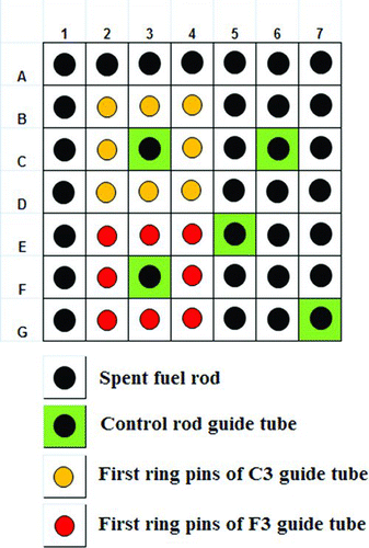
The unfolding method that we propose is as follows. First, a flat pin-wise source strength distribution is set as an initial source distribution. From this distribution, the first ring contribution, which is the ratio of the dose rate from the first ring pins to all existing pins, is calculated, as shown in the following equation. The example of the first ring pins is shown in Figure .
Second, the first ring source strength is calculated based on the measured dose rates using the following equation, which is derived from Equation (7):
Third, the 179 pin-wise source strengths are calculated by fitting the 16 first ring average source strengths with a quadratic function, as shown in the following equation. An assumption is also made that the value at the guide tube position is the average of source strength in the first ring.
The least-square method is used to fit, with the five coefficients of the quadratic function as the unknown parameters, and the 16 average source strengths and their positions as the known parameters. The source strengths of all pins are obtained by applying each pin position to the fitting function. In the next iteration, the new pin-wise source strength distribution corrects the previous first ring contribution and the calculation is repeated with the calculation of the new average first ring source strength.
3. Unfolding execution
3.1. Used experimental data
Sixteen axial gamma dose rate distributions from 16 guide tube measurements of a 14 × 14 Kori Unit 1 spent fuel assembly are used as the main data for the unfolding method. The spent fuel assembly ID is a C15, which has an enrichment of 3.2 wt%, a burnup of 32,000 MWd/tU, and cooling time of 10,176 days. The assembly was measured on 2 February 2010 in spent fuel storage area at the Korea Atomic Energy Research Institute (KAERI), Korea. The assembly was scanned for 200 axial points (2 cm/point) with a time interval of 60 seconds/point. The design specification of the ionization chamber used in the measurement is shown in Table . During the measurement, the detector condition for each data point was kept constant, and the statistic error of the gamma ray measurement is less than 1%.
Table 1 Design specification of the ionization chamber
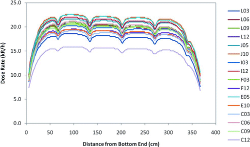
The axial dose rate distributions of the C15 assembly are shown in Figure The axial dose rate distribution represents the relative axial burnup distribution, and the dose rate magnitude represents the relative burnup magnitude. From Figure , it can be seen that there is a large gradient of the dose rate magnitude between the guide tubes, which indicates that there is a large gradient of pin-wise source strength.
3.2. Unfolding procedure
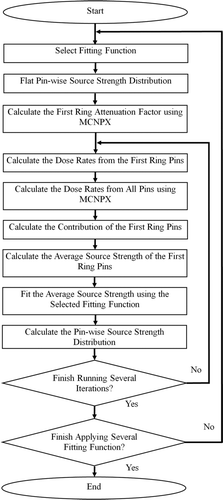
Sixteen gamma dose rates of the C15 assembly are unfolded to 179 pin-wise source strengths. The flowchart of the unfolding procedure is shown in . First, a fitting function is selected, which is used to interpolate or extrapolate the average first ring source strength. Two MCNPX simulations of the measurements at 16 control rod guide tubes are performed with a flat source distribution as input to obtain the attenuation factors from the first ring pins and from all existing pins.
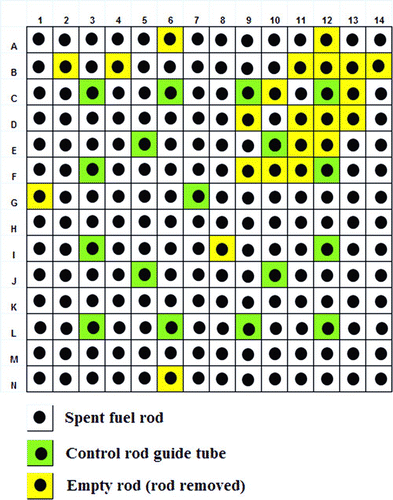
In each MCNPX simulation, the detailed configuration and specification of the measurements are used. The pin-wise configuration of the C15 assembly and the specifications of the fuel assembly are shown in and , respectively. The simulation considers that there are several pins removed from the assembly and only 157 pins exist there. The fuel material and gamma energy information for the simulation is obtained from an ORIGEN-ARP calculation [Citation10]. The library used for the material definition is the ENDF/B-VI. The axial dose rate distribution from the measurement is set as the axial source strength distribution in the simulation. The detectors are located at 181 cm from the bottom end of the assembly where the axial source strength distribution is flat. Even though the simulation is performed at one axial location, the source strength obtained from the simulation is for the total length since the axial source strength distribution is described in the input. The detector tally used in the simulation is the flux averaged over the detector cell in particles/cm2 unit, which is then converted to dose rate using the ICRP-21 1971 dose conversion factor. The NPS (Number of source-Particle historieS) number used is 1 × 10⁹ to achieve tally error within 1%.
Table 2 Specification of the fuel assembly and detector
From the simulations, 16 tallies are obtained at 16 guide tubes. The tallies are the attenuation factors from the source to the detectors since their values are normalized by the source strength, and therefore, should be multiplied with the source strength to obtain the dose rates. Sixteen dose rates from the first ring pins and from all existing pins are obtained and used to calculate the 16 first ring contributions. The contributions are calculated using Equation (7). With these contributions, the first ring pin-wise source strength is calculated using Equation (8). For each guide tube, the measured dose rate is multiplied with the contribution and divided by the attenuation factor from the first ring pins. The first ring source strength is then averaged by the number of pins existing in the first ring, and its value is set at the guide tube position. Sixteen first ring average source strengths at 16 guide tubes are obtained and fitted with the selected fitting function. The position of the pin is determined using the rod pitch length. From the fitting function, the source strengths of all pins are obtained. A new iteration starts with the correction of the first ring contribution based on the new source distribution. Several iterations are performed to study the convergence of the unfolding method. After the desired iteration is finished, a new calculation is started using the newly selected fitting function.
In the case of burnup determination from the unfolded pin-wise source strength distribution, a conversion factor needs to be calculated. This factor can be calculated using ORIGEN-ARP, and the information of cooling time and initial enrichment is crucial. The conversion factor is different for different cooling time and initial enrichment.
4. Results and discussion
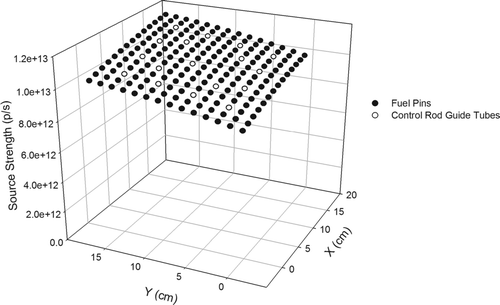
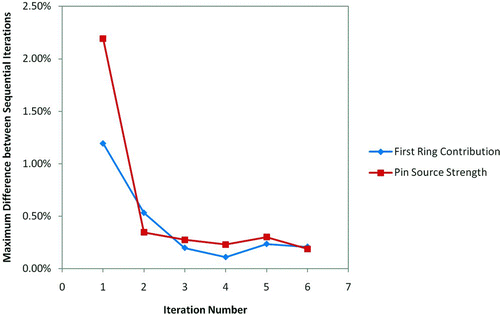
The unfolding method has been applied to the 16 measured dose rates of the C15 assembly. Several fitting functions have been tested and a quadratic fitting function is selected as the best function in terms of the unfolding convergence and the correctness of its solution. The pin-wise source strength distribution obtained from the unfolding is shown in Figure . The distribution is obtained at the sixth iteration, where the maximum difference of the pin-wise source strength between two sequential iterations is about 0.2%. In Figure , the black dots represent the pin-wise source strengths, whereas the white dots represent the guide tube positions only, since there is no source at the guide tube position. As seen from Figure , there is a large gradient of pin-wise source strengths in C15 assembly where the maximum and minimum pin-wise source strength are 1.1220 × 10¹³ and 8.1931 × 10¹² p/s, respectively.
The pin-wise source strength distribution is obtained by iteratively calculating the first ring contribution and average source strength, the quadratic fitting parameters, and the source strengths of all pins. The first ring contribution of each guide tube is shown in Table for the initial and the latest value. As shown in Table , the initial value is close to the latest value, which indicates that the first ring contribution depends weakly on the source distribution. The initial value based on a flat source distribution approximates the latest value very well. The first ring source strength is calculated by multiplying its contribution with the measured dose rate and dividing the result with its attenuation factor. The first ring source strength is then averaged by the number of pins existing in the first ring. The result for each guide tube is shown in Table .
Table 3 First ring contribution
Table 4 First ring average source strength
The average first ring source strength of each guide tube is fitted with a quadratic function, the fitting parameters of which are shown in Table . As shown in Table , there are large differences between the initial and the latest value for c 3 and c 5 coefficients, which indicate that the latest source distribution has more dependency on y in comparison with the initial distribution. This also suggests that several iterations are required to obtain the correct result. The quadratic function fits the average source strengths well with a coefficient of determination (R 2) from the latest fitting of 0.92. The position of each pin is inputted into the quadratic function to calculate the source strength of each pin.
Table 5 Fitting parameters used in the unfolding
In this study, the unfolding method is performed for several iterations without stopping to observe its convergence rate. As shown in Figure , the maximum difference after the first iteration is close to 1%, which indicates that even without an iteration, the calculation of the first ring contribution and the pin source strength approximates the latest calculation well. After the second iteration, the maximum difference is saturated within an error of about 0.2%. This indicates that the unfolding solution is within a 0.2% uncertainty after several iterations. The source of this uncertainty may come from the MCNPX simulation and from the quadratic fitting function.
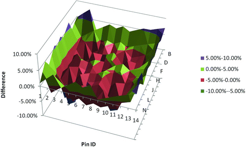
The relative distribution of the pin-wise source strength from the unfolding is checked for its correctness by comparing it with a relative distribution from the design code. To calculate the relative distribution, the source strength of each pin is normalized to the average source strength of all pins. In this paper, the Westinghouse APA code is used as the design code [Citation14, Citation15]. The code consists of the PHOENIX-P and ANC codes, which are 2-D multigroup transport calculation used to generate macroscopic and microscopic parameters of an assembly, and 3-D few-group nodal diffusion calculation used to calculate a pin-wise burnup distribution, respectively. The pin-wise burnup distribution from the design code is converted into a pin-wise source strength distribution using a conversion factor derived from the ORIGEN-ARP calculation.
Figure shows the difference between the relative distribution from the unfolding and the design code. The comparison result shows that the relative distributions from the unfolding and the design code are in a good agreement within 5% difference. Only a few pins have difference above 5%, which are mostly the pins near the boundary of the assembly.
The absolute value of the pin-wise source strength from the unfolding is also checked for its correctness by using it to reproduce the dose rates at 16 control rod guide tubes. The dose rate is calculated using an MCNPX simulation, with the pin-wise source strengths from the unfolding as input. Sixteen dose rates are obtained, as shown in Table , with a comparison with the measured dose rates. The result shows that the dose rates from the unfolding and the measurement are in a good agreement within a 2% difference. This result indicates that the distribution from the unfolding is a good approximate solution of the unfolding problem.
Table 6 Reproduction of dose rates from the unfolding and design code solution
The pin-wise source strengths from the design code are also used to reproduce the dose rates at the measurement points. As previously shown, an MCNPX simulation is used to calculate the dose rates. The dose rates are obtained as shown in Table . It can be seen that the difference between the dose rates from the measurement and the design code is around 10%. One error is around 15% in Table , which seems to originate from a condition where many empty pins are present around the detector.
Since the pin-wise source strengths are obtained, they can be used to calculate the pin burnups. In consideration that the design code has a good ability to predict the burnup distribution, this result indicates that the burnup distribution calculated from the unfolding should be calibrated considering systematic error and efficiency of the detector, and the result has to be verified with the true burnup such as from a chemical assay. The conversion from the pin-wise source strengths to burnups, however, is not within the scope of this paper.
5. Conclusions
An unfolding method has been developed to obtain 179 pin-wise source strengths from 16 measured gamma dose rates at 16 control rod guide tubes of a 14 × 14 PWR spent fuel assembly. The method iteratively calculates and optimizes five coefficients of the quadratic fitting function for X–Y source strength distribution. At the beginning, a flat source distribution is guessed and the first ring contributions are calculated. From the contributions, the first ring average source strengths are calculated and fitted by a quadratic fitting function to obtain all pin-wise source strengths. The 179 pin-wise source strengths are obtained at the sixth iteration, with a maximum difference between sequential iterations of about 0.2%. The convergence rate test shows that the unfolding method converges fast at the first iteration and is saturated within the 0.2% difference, which expectedly comes from the MCNPX and fitting error.
The relative distribution of pin-wise source strength from the unfolding has been checked for its correctness by a comparison with the design code distribution. The result shows that the relative distribution from the unfolding and the design code is consistent within 5% difference. The absolute value of the pin-wise source strengths from the unfolding is also checked by reproducing the dose rates at the measurement points. The result shows that the reproduction of the dose rates from the pin-wise source strength of the unfolding is consistent within a 2% difference.
From the results, the unfolding method is expected to generate a pin-wise source strength distribution, with an error of below 5%, based on the measurements at 16 guide tubes of a 14 × 14 PWR spent fuel assembly. The obtained pin-wise source strengths can be used to determine the pin burnups based on a conversion factor calculated by the ORIGEN-ARP simulation. For future studies, the unfolding method should be tested for other assemblies, and a spent fuel assembly burnup determination using the results from the unfolding should be performed.
References
- Sampson , T E . 1999 . Gamma-ray isotopic analysis development at Los Alamos (LA-13667-MS) , Los Alamos (NM) : National Laboratory .
- Shin , H S , Fo , S G , Seo , K S and Park , S W . 2001 . “ Non-destructive burnup determination of PWR spent fuel using activity ratio Cs-134/Cs-137 ” . In Paper presented at: International Symposium on Radiation Safety Management (ISRSM) Daejeon , Korea 2001 Nov 5–7;
- Berndt , R and Mortreau , P . 2006 . Spent-fuel characterization with small CZT detectors . Nucl Instrum Methods , A 564 : 290 – 294 .
- Park , K J , Ju , J-S , Kim , J-S , Shin , H-S , Chun , Y-B and Kim , H-D . 2009 . Determination of burnup and Pu/U ratio of PWR spent fuels by gamma-ray spectrometry . Nucl Eng Technol , 41 : 1307 – 1314 .
- Willman , C , Håkansson , A , Osifo , O , Bäcklin , A and Svärd , S J . 2006 . Nondestructive assay of spent nuclear fuel with gamma-ray spectroscopy . Ann Nucl Energy , 33 : 427 – 438 .
- Tanskanen , A . 2000 . Assessment of the neutron and gamma sources of the spent BWR fuel , Helsinki , , Finland : STUK . STUK-YTO-TR 170
- Tiitta , A and Hautamäki , J . 2001 . Spent BWR fuel characterisation combining a fork detector with gamma spectrometry , Helsinki , , Finland : STUK . STUK-YTO-TR 175
- Tiitta , A and Hautamäki , J . 2001 . Spent VVER fuel characterisation combining a fork detector with gamma spectrometry , Helsinki , , Finland : STUK . STUK-YTO-TR 181
- Bevard , B B , Wagner , J C and Parks , C V . 2009 . Review of information for spent nuclear fuel burnup confirmation , Washington (DC) : NRC . NUREG/CR-6998
- Bowman , S . 1999 . “ ORIGEN-ARP, A fast and easy-to-use source term generation tool ” . In In: 9th International Conference on Radiation Shielding , Washington , DC : USDOE Office of Science . ICRS-9; 1999 Oct 17–22;
- Chul , G S , Chang , J P and Nam , Z C . 2001 . Pin power reconstruction of HANARO fuel assembly via gamma scanning and tomography method . J Korea Nucl Soc , 13 : 25 – 33 .
- Jacobsson , S . 2002 . Safeguards analysis of tomographic data from a measurements on a PWR nuclear fuel assembly , Helsinki , , Finland : STUK . STUK-YTO-TR 189 – Annex
- Pelowitz , D B . 2005 . MCNPXTM user's manual, Version 2.5.0 (LA-CP-05-0369) , Los Alamos (NM): : National Laboratory .
- Liu , Y S . 1986 . ANC-A Westinghouse advanced nodal computer code , Pittsburgh , PA : Westinghouse .
- Nguyen , T Q , Hoskins , K C , Weber , M M , Srinilta , S , Saji , E , Disney , R K and Durston , C . 1988 . Qualification of the PHOENIX-P/ANC Nuclear Design System for PWR , Pittsburgh , PA : Westinghouse .
