Abstract
A prototype liquid film sensor for high-temperature steam–water experiments has been developed. The sensor shape simulates a boiling water reactor (BWR) fuel rod. The pulse-echo method can be utilized to measure the thickness of the liquid film covering the sensor surface. A piezoelectric element is soldered onto the inside of the sensor casing which consists of two curved casing pieces. After the piezoelectric element is attached, the two casing pieces are laser welded together. It is confirmed that the temperature rise at the time of the laser welding does not influence soldering of the piezoelectric element. The pressure proof test shows that the sensor can be used at a high-pressure condition of 7 MPa. Simple air–water experiments are done at atmospheric pressure to confirm the liquid film thickness can be measured with the sensor. The fluctuation of the liquid film thickness is satisfactorily captured with the sensor. The minimum and maximum thicknesses are 0.084 and 0.180 mm, respectively. The amplitude of the waveform at 286 °C is predicted by the calculation based on the acoustic impedance. It is expected that the sensor is able to measure the liquid film thickness even at BWR operating conditions.
1. Introduction
It is important to clarify the details of two-phase flow phenomena in fuel assemblies for economy and safety improvements of boiling water reactors (BWRs). In some newly developed fuel assemblies, partial length fuel rods and water rods have come to be adopted to improve the fuel performance. As a result, it is necessary to consider the non-symmetries of the fuel assemblies for the thermal–hydraulic performance evaluation. On the other hand, one-dimensional empirical correlations have been used in many conventional performance evaluation programs to predict two-phase flow behavior in fuel assemblies. Therefore, a detailed prediction method to evaluate the performance of non-symmetrical fuel assemblies is desired.
Efforts to develop some models for three-dimensional effects continue to be made for detailed predictions of the two-phase flow behavior in fuel assemblies. Developments of models based on physical phenomena are necessary to handle three-dimensional effects appropriately; in other words, models such as boiling, evaporation, entrainment and deposition in the fuel assemblies are necessary. Regarding the liquid film covering the fuel rods, a mechanistic evaluation model to predict liquid film behavior is also desirable. It is necessary to accumulate various data in high-temperature and high-pressure conditions for these uses. Therefore, it is first necessary to develop some techniques to measure the liquid film behavior in fuel assemblies. The purpose of this study is to develop a liquid film sensor for high-temperature steam–water experiments. The developed sensor should be able to measure the liquid film thickness at BWR operating conditions, i.e. 7 MPa and 286 °C.
Various techniques to measure the liquid film behavior have been developed. Film thickness measurements with a needle contact probe have been done under high-pressure conditions [Citation1]. Annular and tubular test sections were used in these measurements. However, it is not easy to use the needle contact probe in a fuel rod bundle type test section. Recently, the liquid film at 20 °C was visualized as a movie with a high-speed liquid film sensor [Citation2]. The dynamic film behavior around a half cylinder was captured. A flexible multilayer printed circuit board was used to constitute an array of electrode pairs around the half cylinder. Although the sensor is a kind of non-intrusive device, it has not been determined yet whether the sensor can be used under high-temperature conditions. The ultrasonic pulse-echo method was also used for measurements of the liquid film thickness as another non-intrusive measuring technique [Citation3]. The two-dimensional distribution of the liquid film thickness was measured at atmospheric pressure with an ultrasonic device [Citation4]. Because a micro-motor is utilized in the device, it is thought that it is difficult to use the device in a high-temperature steam–water experiment. A final example using an ultrasonic liquid film sensor in steam–water conditions employed polyimide for the liquid film sensor, and the experiment was carried out at 1 MPa [Citation5]. This sensor structure is relatively simple, but it is not clear whether the sensor can be used at 7 MPa.
For the present study, it was decided to apply the ultrasonic pulse-echo method for measurement of the liquid film thickness in high-temperature steam–water two-phase flow tests. A prototype ultrasonic liquid film sensor was developed and a preliminary test was carried out to confirm its performance.
2. Liquid film sensor for steam–water tests
The shape of the prototype liquid film sensor is the same as that of a BWR fuel rod. The sensor structure was designed for use in high-temperature steam–water tests.
2.1. Sensor details
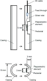
shows a schematic view of the liquid film sensor. The main components of the sensor were two curved casing pieces (10 mm outside diameter) and a piezoelectric element. The casing shape simulated a BWR fuel rod. The piezoelectric element was used to generate an ultrasonic pulse. A pedestal on which the piezoelectric element was fixed was formed inside the casing. Stainless steel (SUS316L) was selected for casing material so that the liquid film sensor could be used in the high-temperature–high-pressure environment.
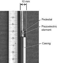
The piezoelectric element was attached to the pedestal with Zn–Al solder (JIS Z 3281). is a photograph of the sensor casing inside which the piezoelectric element was attached. A silver wire was soldered on the piezoelectric element top surface. A mineral-insulated (MI) cable was connected to the silver wire with a feed through (). After having assembled these items inside of the casing, the two curved casing pieces were welded together to form the rod shape. A welding method with a low temperature rise is best suited to prevent the piezoelectric element from coming off or cracking. Instead of the commonly used tungsten inert gas welding, it was judged that laser welding was appropriate.
Lithium niobate (LiNbO3) was selected as the piezoelectric element because its Curie temperature is high (1200 °C). Lithium niobate has been demonstrated to produce a pulse that can be observed at 1000 °C [Citation6]. The single-crystal z-cut was chosen to minimize the thermal expansion coefficient difference between the piezoelectric element and the casing material. The piezoelectric element was 3 mm wide, 5 mm long and 0.7 mm thick. This relatively thick element was used to prevent cracking under the high-temperature conditions. An ultrasonic pulse central frequency of about 5 MHz was generated by the piezoelectric element.
The thickness of the liquid film covering the sensor surface was measured using the ultrasonic pulse-echo method. Two pulses were observed after a pulse was transmitted by the piezoelectric element. One was the reflection at the casing surface and the other was the reflection at the liquid film surface. The liquid film thickness was proportional to the time difference of these pulses.
The pulse was reflected repeatedly in the pedestal. The thickness of the pedestal was designed as 3 mm so that the interval of the multiple reflections became as large as possible. The speed of sound in stainless steel is larger than 5500 m/s when its temperature is lower than 300 °C. Therefore, the interval of the multiple reflections in the pedestal was larger than 1 μs. The overlapping of each pulse did not occur because the pulse width was narrower than 500 ns.
2.2. Applicability of laser welding
Temperature rise at the time of laser welding was examined using a pair of test pieces. The outside diameter of each test piece was the same as the casing diameter. The length of each test piece was 200 mm. Two measurement locations for thermocouples (type K) were used as shown in (a). They were at 30° and 90° positions (P1 and P2) in the circumferential direction from the welding position. The axial position was 75 mm from the edge of the test piece. Sheath diameter of each thermocouple was 1 mm. The laser output and the welding speed were 500 W and 4000 mm/min, respectively. For the 200-mm-long test pieces, laser welding was completed in 3 s. The temperature changes were recorded with a digital recorder (Omniace III RA2300).
Figure 3. Confirmation of temperature rise due to laser welding: (a) measurement point locations; (b) temperature change due to laser welding.
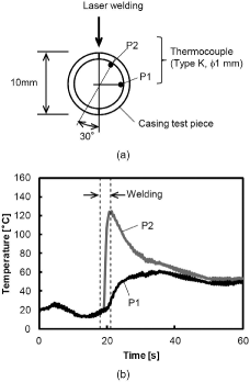
The maximum temperature at the time of the laser welding was 60 °C at P1 ((b)). Even at P2, the maximum temperature was only about 120 °C. Because the melting point of Zn–Al solder is about 380 °C, the temperature rise caused little damage to the soldering of the piezoelectric element.
is a micro photograph of a test piece after laser welding. A casing wall thickness of more than 0.3 mm is necessary so that a circular tube of 10 mm diameter will not rupture for the 7-MPa pressure condition. Since the melting depth of the test piece material was about 0.7 mm, it was judged to be able to use the developed liquid film sensor at the 7-MPa condition.
A pressure proof test was performed to confirm the strength of the laser welded part. End plugs were welded to both axial ends of a test piece. The test piece was exposed to a water pressure of 8.75 MPa for 10 min. After the pressure exposure was stopped, a leak test was performed based on a vacuum method – hood test. The quantity of helium gas leakage was less than 1.6×10⁻¹⁰ Pa·m3/s. It was demonstrated that the liquid film sensor could be used in environments with a pressure of 7 MPa.
3. Liquid film thickness measurements
Simple air–water experiments were performed as the preliminary test to confirm that the liquid film thickness could be measured with the prototype liquid film sensor. Room temperature water was used for the experiments.
3.1. Instrument configuration
Instrument configuration is shown in (a). The MI cable of the prototype liquid film sensor was connected to a pulser-receiver (Panametrics 5800PR). The pulser-receiver transmitted an electrical pulse to generate an acoustic pulse with the piezoelectric element. The reflections of the acoustic pulse were converted to an electrical signal with the piezoelectric element. The signal was received with the pulser-receiver. The output signal of the pulser-receiver was observed as a waveform and recorded with a digital oscilloscope (Tektronix DPO7054). Since the pulse repetition frequency was set to 1 kHz, 1000 waveforms were acquired during 1 s.
Figure 5. Instrument configuration: (a) connection with the instrument; (b) configuration for observing the pulse reflected from the casing surface; (c), (d) configuration for observing the pulse reflected from the liquid film surface.
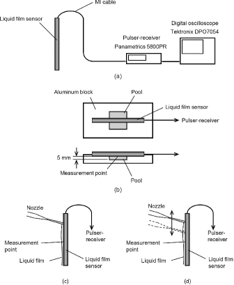
An aluminum block with a small pool was used to simulate a thick liquid film condition ((b)). If the liquid film was thick enough, the pulse reflected at the liquid film surface did not appear on the oscilloscope screen. Then, the displayed waveform accorded with the pulse reflected at the casing surface. This waveform was put into the memory of the oscilloscope as a reference waveform r(t). Although a similar waveform was observed when the casing surface was dry, the amplitude of the waveform was slightly larger than that of the reference waveform r(t). This was because the reflection coefficient at the casing surface became large when the casing surface was dry. The acoustic pulse is strongly reflected when the difference of the acoustic impedance is large. The value of the acoustic impedance becomes smaller in the order of stainless steel > water > air. When the casing surface was dry, the difference between the acoustic impedance inside and outside the casing was large. Then, the amplitude of the reflected acoustic pulse was also large.
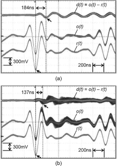
Next, the liquid film sensor was set in the lengthwise direction. A downward flowing liquid film was generated by a small nozzle. In the first case, the nozzle position was fixed ((c)). Then, the nozzle position was slightly moved up and down ((d)). The information about the liquid film thickness was included in the observed waveforms o(t).
3.2. Calculation method of film thickness
According to the pulse-echo method, the liquid film thickness δ is calculated from the time difference Δt between two pulses reflected at the casing surface and the liquid film surface:
(1) where cW is the speed of sound in water.
When the liquid film thickness is very thin, the time difference Δt becomes shorter than the pulse width. Because two pulses arrive at the piezoelectric element with a slight time difference, the observed waveform o(t) shows the summation result of the two pulses. Therefore, the next subtraction,
(2) is necessary to separate the pulse reflected at the liquid film surface [Citation7]. The waveform d(t) provided as the result of the subtraction is referred to as the difference waveform. The difference waveform d(t) can be monitored with the digital oscilloscope.
To determine the time difference Δt between two waveforms r(t) and d(t), the cross-correlation is calculated. The maximum of the cross-correlation indicates the time difference Δt.
3.3. Results of thickness measurements
(a) and (b) is the waveform which was observed when the sensor surface was covered with the liquid film. All waveforms were displayed in the overlay mode of the digital oscilloscope. When the nozzle position was fixed ((a)), every waveform was displayed as a narrow line. The time difference Δt was approximately constant during 1 s. The time difference Δt read with the cursors on the oscilloscope screen is 184 ns. Because the speed of sound in water is 1480 m/s at room temperature, the calculated liquid film thickness was 0.136 mm. When the nozzle position was moved ((b)), wider waveforms were displayed. It was shown that the liquid film thickness changed during 1 s. Because the smallest time difference Δt read with the cursors was 137 ns, the thinnest liquid film thickness was calculated as 0.101 mm. Since the liquid film temperature was not measured in the experiments, the maximum error for the speed of sound was estimated as 1.1%. Further, the reading error of the time difference read with the cursors was 2.8%. Therefore, the error of the liquid film thickness was about 4%.
Figure 6. Waveforms obtained on an oscilloscope: (a) for the fixed nozzle position; (b) for the moving nozzle position.
To examine the liquid film thickness fluctuation, binary waveform files acquired with the digital oscilloscope were analyzed with MATLAB® (MATLAB is a trademark of MathWorks, Inc.). The binary file contained 1000 waveforms in a record. Each waveform was read out sequentially using MATLAB® script. Since the reference waveform r(t) was static, an average waveform (t) was calculated before the thickness calculation. The difference waveform d(t) was calculated sequentially using the average reference waveform
(t) and each observed waveform o(t) which was read from the binary file. Then, the time difference Δt was determined with the cross-correlation between the average reference waveform
(t) and the difference waveform d(t). A MATLAB® function “xcorr” was used to calculate the cross-correlation. The time difference Δt was searched in the range of 1 μs which was equal to the half width of a waveform. In a previous study made by the authors [Citation7], the stable liquid film thickness measured with an ultrasonic transducer was compared with the result of a laser displacement sensor to confirm the suitability of using the difference waveform d(t). The results showed good agreement within the range from 0.06 to 0.22 mm. Furthermore, in the same study, the liquid film thickness of the upward flow in a small square pipe was measured at room temperature. These results showed that the most frequently observed thickness measured with the ultrasonic transducer and a liquid film sensor based on the electrical conductance method was almost the same.
shows the time series liquid film thickness calculated from the waveforms of . In the case when the nozzle position was fixed, the liquid film thickness was almost constant ((a)). The time average thickness was 0.138 mm. On the other hand, fluctuation of the liquid film thickness was captured with the liquid film sensor ((b)). The minimum and maximum thicknesses were 0.084 mm and 0.180 mm, respectively. The time average thickness was 0.126 mm. The minimum liquid film thickness measured with a needle contact probe at 7 MPa was 0.026 mm [Citation1]. Previously, it was confirmed that the liquid film thickness of 0.03 mm could be measured by the ultrasonic measurement technique at room temperature [Citation7]. Furthermore, the speed of sound in water at 286 °C is about two-thirds of the value at room temperature. This means that the travel time in the liquid film becomes long at the high-temperature condition. Therefore, it was expected that the thin liquid film could be measured with the developed liquid film sensor because the resolution of the time difference Δt was not affected by the temperature.
Figure 7. Time series liquid film thickness: (a) for the fixed nozzle position; (b) for the moving nozzle position.
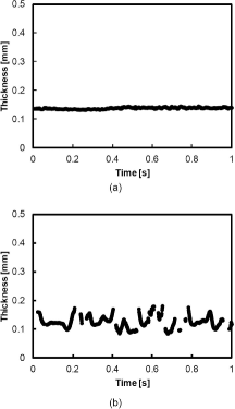
In (b), some discontinuous changes were observed. Serizawa et al. [Citation3] have reported on discontinuous changes. They noted that when the gradient of the liquid film surface was larger than 7°, the reflection pulse could not detect with the ultrasonic transducer of 12.7 mm diameter. The liquid film thickness calculation was skipped when the cross-correlation value was smaller than 0.5; this meant a similar pulse shape was not found in the difference waveform d(t) because the gradient of the liquid film surface was large. When some waves occur on the liquid film surface, the relationship describing the thickness measured with the developed liquid film sensor, the base film thickness and the maximum film thickness is still unclear. In the future, various data to validate the thickness measured with the developed liquid film sensor will be collected.
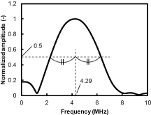
An acoustic frequency characteristic of the liquid film sensor was calculated from the average reference waveform (t). The sampling rate of the average reference waveform
(t) was reduced from 2.5 GS/s to 250 MS/s to examine the frequency characteristic below 10 MHz. A single pulse of 800 ns width around the minimal value of the average reference waveform
(t) was extracted with a rectangular window function. Because the single pulse length had 201 points, zeros were added to increase the pulse length to 4096 points. A discrete Fourier transform was calculated with the MATLAB® function “fft”. shows the acoustic frequency characteristic of the liquid film sensor. It was normalized with the maximum amplitude. Since the central frequency was 4.29 MHz, the half-wavelength in water was 0.172 mm. Because the difference waveform d(t) was utilized to determine the time difference Δt, it was possible to measure the film thickness that was thinner than the half-wavelength.
4. Evaluation of performance in high-temperature condition
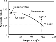
The performance of the liquid film sensor in the high-temperature condition was evaluated. Based on the waveforms which were measured at room temperature, the amplitude of the difference waveform at 286 °C was calculated. For the calculation, transmission and reflection coefficients of the acoustic pressure were utilized. As the liquid film temperature became higher, it was predicted that the transmission coefficient from the sensor to the liquid film decreased. Therefore, it was expected that the thickness measurements would become difficult.
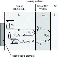
The amplitude of the acoustic pulse generated by the piezoelectric element was assumed to be A0. At the casing surface, the pulse was distributed according to the transmission coefficient T and the reflection coefficient R (). The observed reference waveform r(t) was equivalent to the pulse reflected at the casing surface. Therefore, the amplitude of the reference waveform r(t) was described as RS–WA0. Here, RS–W is the reflection coefficient at the border with stainless steel and water. Similarly, the amplitude of the pulse transmitted to the water was described as TS–WA0. The transmitted pulse was reflected at the liquid film surface and transmitted again into the casing. The amplitude of the transmitted pulse became TS–WRW–ATW–SA0. This value was equal to the amplitude of the difference waveform d(t). Therefore, the amplitude ratio Ar between the difference and reference waveforms could be described as
(3)
The acoustic impedance Z is defined as
(8) where ρ and c are material density and speed of sound, respectively. The material properties of stainless steel, water and air at room temperature are listed in . The amplitude ratio Ar calculated by the acoustic impedances was 0.128 (RS–W = −0.938, TS–WRW–ATW–S = −0.120).
Table 1. Material properties at room temperature (20 °C).
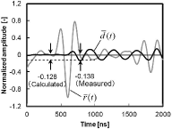
shows the average waveform when the nozzle position was fixed. The gray line is the reference waveform (t) and the black line is the difference waveform
(t). They are normalized with the maximum amplitude of the reference waveform
(t). The broken line indicates the calculated amplitude ratio (Ar)cal of 0.128. It accorded with the measured amplitude ratio (Ar)meas of 0.138. The relative error of the calculated amplitude ratio defined by the next equation,
(9)
The amplitude ratio Ar at 286 °C could be predicted by the same procedure. The material properties at 286 °C are listed in . The speed of sound in stainless steel was the value measured with a stainless steel plate of 25.4 mm thickness. The properties of water and steam were determined with the Japan Society of Mechanical Engineers (JSME) steam tables [Citation8]. shows a predicted curve of the amplitude ratio Ar in the steam–water condition. As the liquid film temperature became higher, the acoustic impedance of the water decreased. Because the transmission coefficient TS−W at 286 °C was 0.033, the amplitude ratio Ar decreased to 0.063. Therefore, the amplitude of the difference waveform at 286 °C was 0.49 times the measured amplitude of the difference waveform at room temperature.
Table 2. Material properties at 286 °C.
The difference waveform d ′(t) at 286 °C was simulated from the measured difference waveform d(t):
(10)
The time series liquid film thicknesses were calculated with the simulated difference waveform d ′(t). As the liquid film thickness was calculated using the cross-correlation function, the results were the same as . Therefore, it was expected that the liquid film thickness could be measured with the developed liquid film sensor even at 286 °C. However, the influence of noise was neglected in this calculation. The sensor performance should be confirmed in a high-temperature steam–water experiment. Although the developed liquid film sensor can be used only in some non-heating steam–water experiment, some useful information to validate a liquid film model will be acquired. It is expected that the liquid film sensor will be used for measurements to expand the database for steam–water two-phase flow.
5. Conclusion
A prototype liquid film sensor for high-temperature steam–water experiments has been developed. The liquid film sensor shape simulated a BWR fuel rod. The sensor diameter was 10 mm. A piezoelectric element was soldered to a pedestal which was formed inside the sensor casing. It was confirmed that the temperature rise at the time of the laser welding did not influence soldering of the piezoelectric element. A pressure proof test was performed to confirm that the liquid film sensor could be used in environments with a pressure of 7 MPa. The thickness of the downward flowing liquid film was measured with the liquid film sensor. The liquid film sensor was able to detect the fluctuation of the liquid film thickness. The relative error of the amplitude ratio between the calculated value using the acoustic impedance and the measured value was 0.08. The amplitude decrease of the difference waveform at 286 °C was predicted by the calculation based on the acoustic impedance. The calculation results showed that the liquid film sensor will be able to measure liquid film thickness even at the BWR operating conditions, i.e. 7 MPa and 286 °C. The effect of amplitude decrease should be confirmed in a high-temperature steam–water experiment.
Nomenclature
| A0: | = | Amplitude of acoustic pulse (Pa) |
| Ar: | = | Amplitude ratio (–) |
| c: | = | Speed of sound (m/s) |
| d(t): | = | Difference waveform (= o(t) − r(t)) (V) |
| d ′(t): | = | Simulated difference waveform (V) |
| o(t): | = | Waveform when the sensor is covered with the liquid film (V) |
| r(t): | = | Reference waveform (V) |
| R: | = | Reflection coefficient (–) |
| t: | = | Time (s) |
| T: | = | Transmission coefficient (–) |
| Z: | = | Acoustic impedance (kg/m2s) |
| Δt: | = | Time difference (s) |
Greek letters
| δ: | = | Thickness (m) |
| ρ: | = | Density (kg/m3) |
Subscripts
| A: | = | Air |
| cal: | = | Calculated value |
| meas: | = | Measured value |
| S: | = | Stainless steel |
| W: | = | Water |
References
- Wurtz J. An experimental and theoretical investigation of annular steam-water flow in tubes and annuli at 30 to 90 bar. Risø report No. 372. Roskilde (Denmark): Risø National Laboratory; 1978.
- Damsohn M, Prasser HM. Experimental studies of the effect of functional spacers to annular flow in subchannels of a BWR fuel element. Nucl Eng Des. 2010;240:3126–3144.
- Serizawa A, Nagane K, Kawara Z, Ebisu T, Torikoshi K. Measurement of liquid film thickness by ultrasonic echo technique. Proceedings of 13th Symposium on Multiphase Flow; 1994 Jul 13–15. Tsukuba (Japan): The Japanese Society for Multiphase Flow; 1994. Japanese.
- Kamei T, Serizawa A. Measurement of 2-dimensional local instantaneous liquid film thickness around simulated nuclear fuel rod by ultrasonic transmission technique. Nucl Eng Des. 1998;184:349–362.
- Sato M, Morooka S, Shirakawa K, Yamamoto Y, Watanabe K, Arai R. Liquid film thickness on fuel rod under high pressure and high temperature steam-water two phase flow. Trans At Energy Soc Jpn. 2006;5(1):14–24. Japanese.
- Baba A, Searfass CT, Tittmann BR. High temperature ultrasonic transducer up to 1000 °C using lithium niobate single crystal. Appl Phys Lett. 2010;97:232901-1-232901-3.
- Aoyama G, Watahiki N, Nagayoshi T, Baba A, Ohtsuka M. Liquid film thickness measurement in small square pipe using ultrasonic pulse-echo method. Proceedings of 19th International Conference on Nuclear Engineering (ICONE19); 2011 Oct 24–25; Osaka (Japan). [CD-ROM].
- The Japan Society of Mechanical Engineers. JSME steam tables. 5th ed. Tokyo: Maruzen; 1999. p. 29–33, 128–131.

