Abstract
As the most promising concept of sodium-cooled fast reactors, the Japan Atomic Energy Agency (JAEA) has selected the advanced loop-type fast reactor, so-called JSFR. The safety design requirements of JSFR for Design Extension Condition (DEC) are the prevention of severe accidents and the mitigation of severe-accident consequences. For the mitigation of severe-accident consequences, in particular, the In-Vessel Retention (IVR) against postulated Core Disruptive Accidents (CDAs) is required. In order to investigate the sufficiency of these safety requirements, a CDA scenario should be constructed, in which the elimination of power excursion and the in-vessel cooling of degraded core materials are evaluated so as to achieve IVR. In the present study, the factors leading to IVR failure were identified by creating phenomenological diagrams, and the effectiveness of design measures against them were evaluated based on experimental data and computer simulations. This is an unprecedented approach to the construction of a CDA scenario, and is an effective method to objectively investigate the factors leading to IVR failure and the design measures against them. It was concluded that mechanical/thermal failures of the reactor vessel due to power-excursion/thermal-load could be avoided by adequate design measures, and a clear vision for achieving IVR was obtained.
1. Introduction
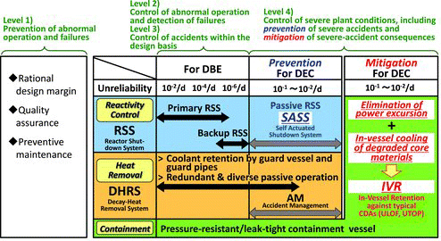
As the most promising concept of sodium-cooled fast reactors (SFRs), the Japan Atomic Energy Agency (JAEA) has selected the advanced loop-type fast reactor, so-called Japan Sodium-cooled Fast Reactor (JSFR) [Citation1]. One of the safety design requirements of JSFR for Design Extension Condition (DEC) is the control of severe plant conditions, including prevention of severe accidents and mitigation of severe-accident consequences. The basic framework of safety design in JSFR is schematically displayed in .
For the prevention of severe accidents, as shown in , passive Reactor Shutdown System (RSS) and redundant/diverse Decay Heat Removal System (DHRS) are introduced to JSFR. As the passive RSS, Self-Actuated Shutdown System (SASS) utilizing a Curie-point magnet is adopted to the JSFR design [Citation2]. As the redundant/diverse DHRSs, one loop of direct reactor auxiliary cooling system (DRACS) and two loops of primary reactor auxiliary cooling system (PRACS) are introduced [Citation3]. These DHRSs can be operated under fully passive conditions, which require only the actuation of the direct-current-power-operated dampers of the air coolers without pumps and blowers.
For the mitigation of severe-accident consequences, on the other hand, the elimination of power excursion due to recriticality and the in-vessel cooling of degraded core materials are required in JSFR. In order to achieve the In-Vessel Retention (IVR) against CDAs, the conceptual design study of JSFR and the development of innovative technologies have been promoted [Citation4]. The design measures to achieve IVR by the elimination of power excursion and in-vessel cooling of degraded core materials constitute the fourth-level of defense-in-depth for the mitigation of severe-accident consequences as shown in .
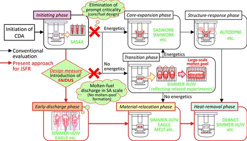
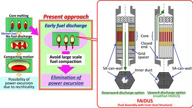
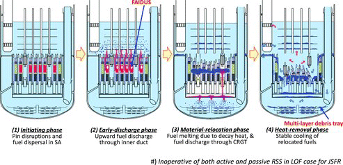
In the conventional approach to mitigate CDA consequences, severe recriticality events have played a major role and the focus has been on how to withstand such events. In the present approach for JSFR, on the other hand, elimination of such severe recriticality events will be achieved by introducing the adequate design measures and by evaluating their effectiveness based on newly obtained experimental data and validated computer simulations. The conventional and present approaches can be compared in , where the related experiments and computational tools are roughly displayed. In the present approach for JSFR, core design and fuel characteristics are intended to eliminate the possibility of prompt criticality leading to mechanistic core expansion. In addition, the fuel assembly, so-called FAIDUS (Fuel Assembly with Inner-Duct Structure) [Citation5], will be introduced as a design measure for realizing early fuel discharge before the formation of a large-scale molten pool, which has recriticality potential due to large-scale fuel compaction. The concept of early fuel discharge and two design options for FAIDUS are shown in . Since the downward-discharge option involves difficulties in fabrication using a grid-type spacer, the feasibility of the upward-discharge option driven by the pressurization of the disrupted core has been investigated by utilizing the phenomenological evidences obtained through well-designed experiments. The EAGLE project, which includes out-of-pile and in-pile tests, was planned for this purpose and has been successfully conducted [Citation6]. Concerning the subsequent phases, i.e. the material-relocation phase and heat-removal phase shown in , the importance of IVR and the method of its demonstration have been also pointed out. For these two phases, however, the phenomena and event progressions were not systematically assessed, and the quantitative evaluations for them were still insufficient.
In the present paper, a CDA scenario for JSFR aiming the elimination of power excursion due to recriticality and the in-vessel cooling of degraded core materials is constructed so as to achieve IVR. In order to evaluate the feasibility of IVR, the factors leading to IVR failure were identified by creating phenomenological diagrams, and the effectiveness of design measures against them were evaluated based on existing experimental data and computer simulations with validated analytical tools. This is an unprecedented approach to the construction of a CDA scenario, and is an effective method to objectively investigate the factors leading to IVR failure and the design measures against them. The phenomenological event progressions, in particular for the material-relocation and heat-removal phases, are quantitatively evaluated for the first time in the world.
2. Approach to in-vessel retention (IVR)
2.1. Selection of representative initiator
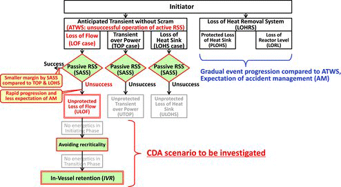
A CDA scenario means the phenomenological event progression up to stable cooling conditions, which can be reasonably estimated/assessed based on theoretical considerations, experimental data basis, and state-of-the-art analyses. In the JSFR design, the passive reactor shutdown system SASS is installed to safely terminate ATWS (Anticipated Transient without Scram), where ATWS is caused by the unsuccessful operation of active reactor shutdown systems in anticipated transients, and has a small expectation of recovery by accident-management measures compared to the LOHRS (Loss of Heat Removal System) case. In general, ATWS consists of LOF (Loss of Flow), TOP (Transient over Power), and LOHS (Loss of Heat Sink) cases as shown in . In all types of ATWS, the LOF case has a smaller safety margin offered by SASS, and has a higher probability of leading to CDA compared with the TOP and LOHS cases [Citation2]. In addition, the LOF case has a comparatively high power-excursion potential due to coherent coolant boiling. Hence, ULOF (unsuccessful operation of both active and passive RSSs in the LOF case) was selected as a representative initiator, and the CDA scenario against ULOF was investigated here.
2.2. Categorization of whole sequence
In the construction of the CDA scenario, at first, a most probable sequence was investigated taking into account the various phenomena appearing in the event progression and the various design measures to be applied to the device designs. According to the core-disruption status, the whole sequence was categorized into the following four phases as shown in : (1) initiating phase, (2) early-discharge phase, (3) material-relocation phase and (4) heat-removal phase. Here, the “early-discharge phase” means a phase in which the molten fuel could be discharged, before the formation of a large-scale molten-core pool, by an adequate design measure such as FAIDUS. This phase was newly defined instead of the so-called “transition phase” which has recriticality potential due to large-scale fuel compaction in the molten-core pool (see ).
2.3. CDA Scenario to be achieved and conditions to be satisfied
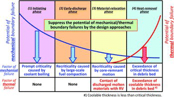
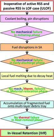
For avoiding IVR failure, both the mechanical boundary failure due to power excursion and the thermal boundary failure due to incomplete stable cooling should be prevented by adequate design measures. The power excursion will challenge the integrity of the core structure and reactor vessel (RV), which are discussed for the core-expansion phase in the conventional evaluation as shown in . The incomplete stable cooling, on the other hand, will result in the heating up of the cooling system and the excess heating of RV caused by the direct contact of molten-core materials.
The potential of mechanical and thermal boundary failures can be schematically depicted as shown in , where the main factors of mechanical/thermal failures will be discussed in Chapter 4. Concerning the potential of mechanical boundary failure, the initiating phase has the possibility of energetics that are severe enough to threaten the integrity of RV, due to the “LOF-driven-TOP” mechanism because of the large void worth. In the subsequent phases, however, the potential of mechanical boundary failure will generally decrease because the degraded fuels in the disrupted core tend to be dispersed toward the reactor vessel (RV) and the possibility of rapid fuel compaction will be reduced. The potential of thermal boundary failure, on the other hand, will generally increase toward the heat removal phase because the discharged fuel from the core region will be close to RV.
In order to avoid IVR failure, therefore, the following conditions should be satisfied by adequate design measures and by proper evaluations:
For the initiating phase:
No mechanical failure due to power excursion.
For the early-discharge phase:
No mechanical failure due to power excursion.
For the material-relocation phase:
No mechanical failure due to power excursion, and
No thermal failure due to unsuccessful stable cooling.
For the heat-removal phase:
No thermal failure due to unsuccessful stable cooling.
Therefore, the CDA scenario to be achieved through the evaluation above can be displayed as shown in .
3. Requirements and Measures to achieve IVR
3.1. Evaluation Procedures
Before the evaluation of the IVR feasibility against ULOF, phenomenological diagrams were created as the first step, in which the factors and elements leading to IVR failure and the relationships among them were exhaustively displayed. In the next step, the design measures against them were considered. This is an unprecedented approach to the construction of a CDA scenario, and is an effective method to objectively investigate the factors leading to IVR failure and the design measures against them. Contrary to the traditional way to construct CDA scenarios, which depend on expert judgments, our methodology can provide objective and persuasive conclusions to the CDA evaluation.
3.2. Construction of Phenomenological Diagram
The higher-level diagrams are presented in , in which “IVR failure” is positioned as the top event and factors leading to mechanical/thermal boundary failures are displayed.
Figure 8. Identification of factors leading to IVR failure by constructing phenomenological diagrams.
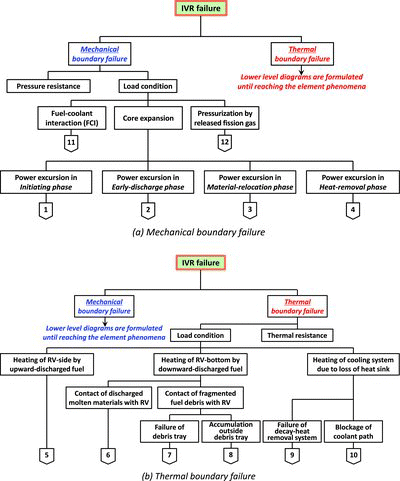
As shown in (a), it is obvious that the mechanical boundary failure can be avoided if the pressure resistance of RV is superior to the load conditions such as “Fuel-coolant interaction (FCI),” “Core expansion,” and “Pressurization by released fission gas.” Among these mechanical load conditions, “FCI” in sodium-cooled reactors will not be significant compared to that in light-water reactors due to the higher thermal conductivity of sodium (see Section 4.3.4). Contrary to the pressurization due to FCI and/or core expansion, “Pressurization by released fission gas” will progress gradually and can be managed by handling the system-relief valves. The “Core expansion,” therefore, will be the dominant factor leading to the mechanical boundary failure, which can be categorized to the power excursions in the initiating, early-discharge, material-relocation, and heat-removal phases.
As shown in (b), it is also obvious that the thermal boundary failure can be avoided if the thermal resistance of RV is superior to the load conditions such as “Heating of RV-side by upward-discharged fuel,” “Heating of RV-bottom by downward-discharged fuel,” and “Heating of cooling system due to loss of heat sink.” Among these thermal load conditions, “Heating of cooling system due to loss of heat sink” should be discussed for gradual event progressions as shown in LOHRS, and will not have a significant effect on the rapid event progression as shown in the ULOF case which is selected as the representative initiator here. The element factors leading to “Heating of RV-side by upward-discharged fuel” are essentially the same as those leading to “Heating of RV-bottom by downward-discharged fuel” except for the discharge direction, where the former has upward discharge by FAIDUS and the latter has downward discharge through CRGT. In addition, the upward-discharged fuel, which has a smaller amount compared to the downward-discharged fuel, will be relatively well cooled in the upper plenum region. The factors leading to “Heating of RV-bottom by downward-discharged fuel,” therefore, are practically investigated here, which consist of “Contact of discharged molten materials with RV” and “Contact of fragmented fuel debris with RV.”
By adopting a similar methodology, lower-level diagrams were also formulated by digging down from the connection numbers 1–12 in until the elemental phenomena were reached as described in Chapter 4.
3.3. Required conditions and design measures
In the next step, the current knowledge of related experiments and analytical data was applied to the phenomenological diagrams, and the required conditions and the design measures to achieve IVR were investigated. The design measures investigated by these procedures are summarized in .
Table 1. Required conditions and design measures for IVR.
As described in Section 2.3, the mechanical boundary failure should be avoided in the initiating, early-discharge and material-relocation phases. To satisfy the mechanical conditions during these three phases, both prompt criticality and recriticality should be prevented by adequate design measures such as core/fuel designs, installation of FAIDUS, and enhancement of fuel discharge through CRGT. Thermal boundary failure, on the other hand, should be avoided in the material-relocation and heat-removal phases. To satisfy the thermal condition during these two phases, the contact of discharged molten materials with RV and the excess of debris-bed thickness should be prevented by adequate design measures such as plenum design for quenching and installation of multi-layer debris tray.
The effectiveness of the design measures above and the feasibility of IVR will be discussed in the next chapter.
4. Evaluations to achieve IVR
The effectiveness of design measures displayed in is evaluated based on the experimental data and computer simulation with validated analytical tools. In this chapter, the identification of main factors leading to IVR failures, the evaluation of design-measure effectiveness, and the feasibility of IVR are discussed. Compared to the past investigation of CDA for JSFR [Citation7], the present paper for the first time provides an evaluation in which the material-relocation and heat-removal phases are quantitatively investigated.
4.1. Initiating phase
4.1.1. Outline of evaluation process
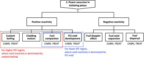
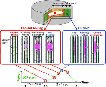
In the initiating phase, the IVR failure is dominated by mechanical boundary failure as described in Section 2.3. The main factor of mechanical boundary failure is the power excursion due to the prompt criticality caused by coolant boiling as shown in . The design measure to avoid the power excursion is the suppression of maximum void worth below 6$. This design measure was assessed and evaluated as described below.
4.1.2. Identification of reactivity-feedback factors
As shown in , the lower-level diagram for the initiating phase was formulated by digging down from the connection number 1 in (a), in which the factors of positive and negative reactivity-feedback were identified. The reactivity-feedback factors identified from this diagram can be summarized as below:
Positive reactivity feedback
Coolant boiling for higher P/F (Power/Flow-rate) region around inner core
FCI-void development, which is caused by the contact of molten fuel with sodium coolant due to cladding rupture in lower P/F region around outer core
Cladding motion
Fuel compaction
Negative reactivity feedback
Fuel Doppler effect
Fuel axial expansion
Fuel dispersal
The condition for avoiding the prompt criticality was determined based on theoretical considerations [Citation7] according to the event progression, in which the negative reactivity feedback due to fuel dispersal should become effective before the prominence of void reactivity due to coolant boiling and/or FCI-void development. The phenomena in the initiating phase, to be expected by taking the suppression of void worth as the design measure, can be illustrated in .
4.1.3. Parametric analyses by SAS4A
The limitation of void worth under which the power excursion due to prompt criticality could be avoided was evaluated by parametric analyses using the SAS4A code [Citation7,8], taking into account the uncertainty of reactivity-worth estimation. The suppression of void worth less than about 6$ as the design measure was obtained from these parametric analyses.
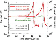
The SAS4A code is validated based on the in-pile/out-of-pile experiments, such as CABRI, etc. [Citation7]. The condition not to exceed the prompt criticality during the initiating phase was investigated through parametric analyses by the validated SAS4A. In some cases for the maximum void worth above 6.5$ within the parametric surveys [Citation8], it was found that a power excursion might take place before the significant fuel dispersal. However, by suppressing maximum void worth to below 6$ including its uncertainty corresponding to twice the standard deviation, power excursion due to prompt criticality could be prevented as shown in the dotted lines of . The core and fuels of JSFR designed with a maximum void worth in 5$, therefore, can avoid the power excursion as shown in the solid lines of .
4.1.4. Evaluation results and future issues
The parametric analyses by SAS4A code showed that the core and fuels of current JSFR design could satisfy the required condition for preventing the power excursion in the initiating phase.
The present evaluation will be updated in accordance with progress in core/fuel designs, but at the current stage there are no major issues to be solved in the future.
4.2. Early-discharge phase
4.2.1. Outline of evaluation process
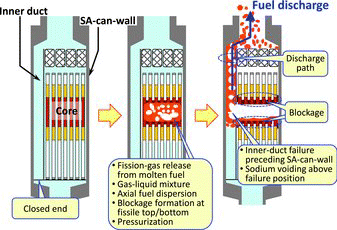
In the early-discharge phase, IVR failure is dominated by mechanical boundary failure. The main factor of mechanical boundary failure is the power excursion due to recriticality caused by large-scale molten-fuel compaction as shown in . The design measure to avoid the power excursion is the installation of FAIDUS (see ) for discharging molten fuel before the formation of a molten-core pool. In this design measure, the inner-duct failure and upward fuel-discharge should precede the subassembly (SA) can-wall failure. The effectiveness of this design measure was assessed and evaluated as described below.
4.2.2. Identification of discharge mechanism based on experiments
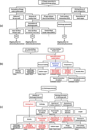
As shown in , the lower-level diagram for the early-discharge phase was formulated by digging down from the connection number 2 in (a). Based on , the factors to be investigated for upward-discharge behavior were clarified by comparison with the current status of related experimental/computational studies. The key factors identified from the diagram can be summarized as below:
Wall deformation and/or failure of inner duct (ID) and SA can-walls
Heat transfer from molten core materials
Cooling of structure by sodium
Driving force for upward discharge
Pressurization inside SA by blockage formation at fissile top/bottom and fission-gas release from fuel pellets
Separation of fission gas from molten fuel
Slip between fission gas and molten fuel in ID
In accordance with the phenomena (see ) to be expected in the early-discharge phase, the feasibility of FAIDUS in upward-discharge option was investigated based on out-of-pile/in-pile experiments. It was confirmed by the WF (wall failure), FD (fuel discharge) and ID (integral demonstration) tests of EAGLE project [Citation6,Citation9] that the inner-duct failure would precede SA-can-wall failure [Citation7], and it was also confirmed by the E13 and TP2 tests of CABRI program [Citation10,11] and PFR experiments of TREAT program [Citation12,13] that a sufficient driving force for upward discharge would be obtained.
4.2.3. Reactivity evaluation by SIMMER-III
The behavior of fuel discharge through the inner duct was evaluated by parametric analyses using the SIMMER-III code, taking into account the uncertainty of wall deformation and/or failure.
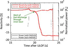
The SIMMER-III code has been validated through many experimental analyses and reactor applications [Citation14,15]. In addition, the experimental knowledge obtained in the EAGLE project, such as the heat flux from molten core material and the wall-failure mechanism, were also reflected [Citation16,17] in the current SIMMER-III evaluation. In order to conservatively evaluate the uncertainty of discharge behavior, it was assumed in the present calculations that the wall-failure due to mechanical load would take place at the onset of wall-deformation. The effect of FAIDUS on the reactivity transient is displayed in , where the first power peak around 19 seconds was caused by the positive reactivity feedback due to the coolant boiling and FCI-void development in the initiating phase, and the fuel melting derived by this power peak would be meaningful to the evaluation of fuel-discharge behavior in the early-discharge phase. shows that, in the case without FAIDUS, recriticality and remarkable power peak would take place due to the fuel compaction in the molten-core pool. In the case with FAIDUS, on the other hand, molten-fuel discharge through the inner duct before the formation of a molten-core pool would bring the significant reduction of reactivity/power. In addition, the mobility of the core remnant after the upward discharge by FAIDUS should be significantly low because the molten fuel would be removed and only solid fuel would be left in the core region [Citation18]. Even including the uncertainty of duct-failure-time estimation, FAIDUS can avoid the power excursion due to recriticality.
4.2.4. Evaluation results and future issues
The parametric analyses by SIMMER-III code showed that the molten fuel can be discharged by FAIDUS before the formation of a molten-core pool, and the power excursion due to recriticality could be avoided.
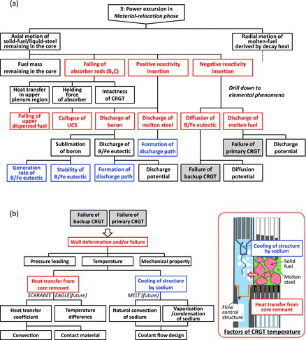
In order to reduce the uncertainty of wall deformation and/or failure, we intend to clarify the mechanical property of inner-duct and SA-can-walls by obtaining the irradiated material-strength data under disrupted core conditions. As shown in the lower-level diagram of (b), the wall deformation and/or failure are dominated by the pressure loading, mechanical property, and temperature of structures. The material strength data to be obtained in the future will reduce the uncertainty in the evaluation of inner-duct and SA-can-wall failures. In addition to these experimental data, the analytical models in SIMMER-III for upward-discharge behavior should be further validated utilizing the results of the EAGLE project. These experimental data and code validation will contribute to improvements in the evaluation method of upward fuel-discharge behavior in the early-discharge phase.
4.3. Material-relocation phase
4.3.1. Outline of evaluation process
In the material-relocation phase, IVR failure is dominated by both mechanical and thermal boundary failures. The main factor of mechanical boundary failure is the power excursion due to recriticality caused by core-remnant motion, where the mobility of fuel remaining in the core region would be significantly low in the early stage but would gradually increase due to the fuel melting by decay heat in the late stage. The design measure to avoid the power excursion is the enhancement of molten-fuel discharge through control rod guide tubes (CRGTs). The main factor of thermal boundary failure, on the other hand, is the excess heating of the reactor vessel (RV) caused by the direct contact of discharged molten materials with RV. The design measure to avoid the excess heating of RV is the design optimization of the inlet/lower plenums with the aim of quenching discharged molten materials. The effectiveness of these design measures was assessed and evaluated as described below.
4.3.2. Identification of reactivity-insertion factors for mechanical boundary failure
As shown in , the lower-level diagram for the mechanical boundary failure in the material-relocation phase was formulated by digging down from the connection number 3 in (a). Based on , the factors to be investigated for positive and negative reactivity-insertion events were clarified by comparison with the current status of related experimental/design studies. The key factors identified from the diagram can be summarized as below:
Falling of absorber rods (B4C)
Positive reactivity-insertion events
Falling of upper dispersed fuel
Collapse of Upper Core Structure (UCS)
Discharge of boron
Discharge of molten steel
Negative reactivity-insertion events
Diffusion of B/Fe eutectic due to failure of backup CRGT
Discharge of molten fuel due to failure of primary CRGT
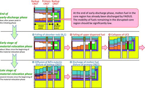
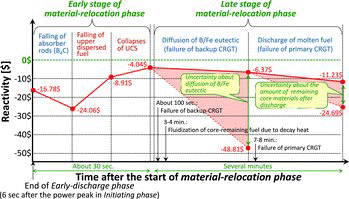
Although ULOF would be initiated by the unsuccessful operation of SASS in the LOF case as explained in , the absorber rods of backup CRGT held by the Curie-point magnet are assumed to have fallen down since no magnetic force to hold absorber rods is available in the beginning of the material-relocation phase. Considering the event progression associated to the reactivity insertion above, the phenomena expected in the material-relocation phase are displayed in . The phenomenological sequence of material/thermal distributions according to the structure failure, which are described later, is schematically reflected to this figure. As shown in , the material-relocation phase can be divided into two stages according to the fuel conditions in the core region. In the early stage of the material-relocation phase, the mobility of fuels in the core region should be significantly low because the molten fuel has already been discharged by FAIDUS, and the axial movement of core materials such as falling of upper dispersed fuel and collapse of UCS would be dominated by the thermal conditions at the end of early-discharge phase. In the late stage of the material-relocation phase, on the other hand, the B/Fe eutectic derived by falling down of absorber rods would be diffused, and the fuels remaining in the core region would gradually melt due to decay heat and be discharged through primary CRGTs.
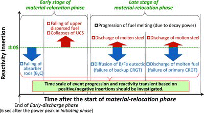
The reactivity insertion due to the expected phenomena in these two stages can be displayed in . In order to assess the phenomenological sequence of material/thermal distributions according to the structure failure, the time of CRGT failures and progress of fuel melting due to decay heat were evaluated using the related experimental data and the adequate computational tools as below. The evaluation results obtained from them were efficiently reflected in and .
Failure of backup CRGT:
Since the absorber rods of backup CRGT held by the Curie-point magnet are assumed to have fallen down, the sodium coolant inside the backup CRGT will be excluded. The backup CRGT, hence, cannot be expected to be the discharge path of the core remnant. The cooling of structure by the sodium inside the backup CRGT would not be remarkable. In the evaluation of breakup behavior for the backup CRGT, the heat transfer from core remnant toward CRGT predicted by the BE+3/BF3 tests in the SCARABEE experiments was reflected to SIMMER-III code, because the flow-regime model of the original SIMMER-III has not completely enveloped the heat transfer condition where the convection of molten steel is limited by the fuel particles remaining in the core region as expected after the end of the early-discharge phase.
Taking into account the heat transfer from core remnant and the cooling of structure by sodium mentioned above, the failure of the backup CRGT was evaluated with SIMMER-III code. SIMMER-III evaluation showed that about 100 seconds would elapse after the beginning of the material-relocation phase before the failure of the backup CRGT. The breakup of the backup CRGT will derive the diffusion of B4C and generation of B/Fe eutectics in the core region.
Failure of primary CRGT:
Since the absorber rods of the primary CRGT, independent of the backup-CRGT system, should not fall down during the entire CDA sequences, the sodium coolant will remain inside the primary CRGT at the beginning of the material-relocation phase. The primary CRGT, hence, can be expected to be the discharge path of core remnant, in particular the molten fuel due to decay heat. The cooling of structure by the sodium would be enhanced by the natural convection inside the primary CRGT (see the right-hand side illustration of (b)). In the evaluation of breakup behavior for the primary CRGT, as well as the backup CRGT, the heat transfer from core remnant toward CRGT predicted by the BE+3/BF3 tests in the SCARABEE experiments was reflected in SIMMER-III code.
Taking into account the heat transfer from core remnant and the cooling of structure by sodium mentioned above, the failure of the primary CRGT was evaluated with SIMMER-III code. SIMMER-III evaluation showed that 7–8 minutes would elapse after the beginning of the material-relocation phase before the failure of the primary CRGT. The breakup of the primary CRGT will derive the discharge of molten core materials, which are gradually fluidized by decay heat.
Progress of fuel melting due to decay heat:
Since the molten fuel has already been discharged by FAIDUS, the solid fuel should remain in the core region at the early stage of the material relocation phase. This solid fuel would gradually melt due to decay heat, and be discharged through the primary CRGT. The power density of decay heat has a distribution in the disrupted core region, which is derived by the material distribution after the early-fuel discharge by FAIDUS. In the evaluation of the melting of the solid fuel remaining in the core region, the heat transfer from core remnant to the surrounding structures predicted by the BE+3/BF3 tests in the SCARABEE experiments was reflected.
Taking into account the decay heat in accordance with the core remnant distribution and the heat transfer from core remnant to the surrounding structures mentioned above, the progress of fuel melting and fluidization due to decay heat was evaluated with TAC-2D code [Citation19]. TAC-2D evaluation showed that 3–4 minutes would elapse after the beginning of the material-relocation phase before the start of fluidization. The fuel melting and fluidization due to decay heat is local, and they will not lead to the formation of a whole-core molten pool.
The evaluations above suggest that the molten fuels due to decay power heat would be discharged through primary CRGT before the formation of a whole-core pool. Since the progress of solid-fuel melting due to decay heat would precede the breakup of primary CRGT, the discharge of molten fuel should accompany the molten steel. In other words, the negative reactivity insertion due to the discharge of molten fuel become effective before the prominence of positive reactivity insertion caused by the discharge of molten steel with B/Fe eutectic. Based on the evaluation above, the enhancement of molten-fuel discharge through primary CRGT was identified as the design measure for avoiding power excursion due to recriticality.
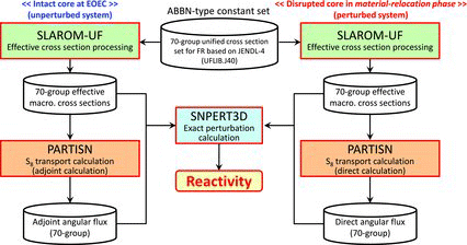
4.3.3. Reactivity evaluation by perturbation calculation for mechanical boundary failure
The reactivity transient in the material-relocation phase was evaluated by a series of exact perturbation calculation based on transport theory, taking into account the expected phenomena and design measures against the power excursion. The concept of exact perturbation calculation is schematically shown in , and the evaluated reactivity transient is displayed in . As shown in , the significant reactivity insertion would be avoided by the enhancement of fuel discharge through primary CRGTs, and the sub-critical state would be ensured during the material–relocation phase including the uncertainty of phenomenological events such as the diffusion of B/Fe eutectic generated by backup-CRGT failure, and the amount of remaining core materials after the fuel discharge through primary CRGTs.
4.3.4. Investigation of jet-breakup behavior in SFR for thermal boundary failure
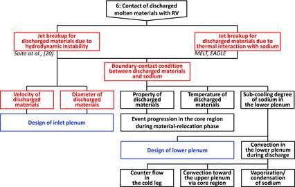
As shown in , the lower-level diagram for the thermal boundary failure in the material-relocation phase was formulated by digging down from the connection number 6 in (b). Based on , the factors to be investigated for avoiding the direct contact of discharged molten materials with RV were clarified by comparison with the current status of related experimental/design studies. The key factors identified from the diagram can be summarized as below:
Jet breakup for discharged materials due to hydraulic instability
Jet breakup for discharged materials due to thermal interaction with sodium
Boundary contact condition between discharged materials and sodium
Velocity of discharged materials
Diameter of discharged materials
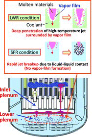
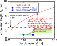
For the LWR (Light Water Reactor) conditions, the jet breakup due to hydraulic instability has been investigated [Citation20]. In SFR (Sodium-cooled Fast Reactor) conditions, in contrast to LWR conditions, the thermal interaction between the discharged molten materials and sodium coolant in the lower plenum will significantly affect the jet-breakup behaviors, which are dominated by the contact condition between discharged materials and sodium, and velocity/diameter of discharged materials. The jet-breakup behaviors in SFR condition was surveyed based on related past experiments [Citation21,22]. The feature of jet breakup in LWR and SFR conditions are schematically illustrated in . The difference between them can be summarized as follows:
Jet-breakup of molten core materials in LWR
Formation of vapor film on the jet surface
Low heat transfer from the discharged/ injected materials to coolant due to the vapor film
Deep penetration
High possibility of direct contact to RV
Jet-breakup of molten core materials in JSFR
No significant vapor film on the jet surface
High heat transfer from the discharged/ injected materials to coolant due to the liquid-liquid contact
Rapid jet breakup
Low possibility of direct contact to RV
The fragmentation of core materials due to the jet breakup would significantly contribute to the effective cooling of discharged materials and the avoidance of thermal boundary failure.
4.3.5. Prediction of jet-breakup length for thermal boundary failure
The fragmentation of core materials could be achieved by controlling the discharge condition from the inlet plenum and by ensuring a sufficient amount of sodium in the lower plenum through the design optimization of these plenums. Although experimental data for the jet-breakup length for UO2 in sodium pool [Citation22] is few and limited, the mechanism of jet breakup under SFR condition has been clarified [Citation23]. Based on these experimental data and related studies, it can be expected that the breakup length would be less than the height of the lower plenum as shown in . The figure suggests that the discharged molten materials would rapidly break up within the lower plenum. In order to assemble a database on the breakup length under SFR conditions and to obtain the empirical correlations to evaluate it, a series of new experiments has been executed by the JAEA. The breakup length in SFR conditions evaluated by these experiments and empirical correlations will be reflected in the detailed design of inlet/lower plenums of JSFR in the future.
4.3.6. Evaluation results and future issues
The reactivity evaluation by exact perturbation calculation suggests that the sub-critical state could be ensured and the power excursion due to recriticality could be avoided by adequate design measures such as enhancement of fuel discharge through primary CRGT. In order to reduce the uncertainty of discharge evaluation through CRGT, we are planning new experiments to obtain the thermal loading and inside coolability on CRGT under conditions corresponding to the material-relocation phase. In addition, the generation rate and diffusion behavior of B/Fe eutectic should be further clarified in the future for supporting the current conclusion.
The investigation of jet-breakup behaviors under SFR conditions, on the other hand, showed that the discharged molten materials would rapidly break up within the lower plenum and the thermal boundary failure due to the direct contact of molten materials with RV could be avoided by the design optimizations of inlet/lower plenums. In order to reflect the experimental knowledge in the detailed design of inlet/lower plenums, such as controlling the jet diameter, the empirical correlations for the breakup length taking the feature of SFR conditions into consideration will be obtained in the future.
4.4. Heat-removal phase
4.4.1. Outline of evaluation process
In the heat-removal phase, IVR failure is dominated by thermal boundary failures. The main factor of thermal boundary failure is the incompleteness of stable cooling due to the thickness of debris bed exceeding the coolable limit. This debris bed would be formed by the accumulation of fragmented core materials. As one of the features of JSFR design, the fuel inventory is comparatively large in respect to RV diameter. Hence, the design measure to avoid the incompleteness of stable cooling is the installation of multi-layer debris tray to enhance debris dispersion and to suppress the debris thickness below the coolable limit.
The effectiveness of this design measure was assessed and evaluated as described below.
4.4.2. Consideration of debris-tray configuration to enhance debris dispersion
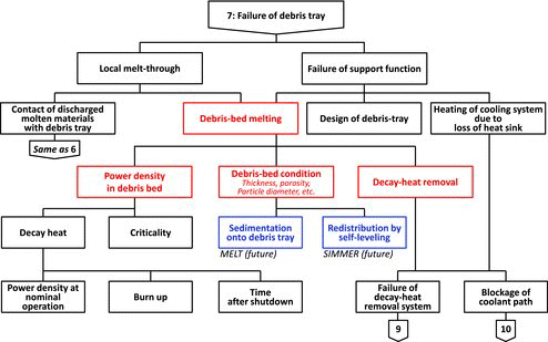
As shown in , the lower-level diagram for the heat-removable phase was formulated by digging down from the connection number 7 in (b). Based on , the factors to be investigated for stable cooling by avoiding debris-bed melting were clarified by comparison with the current status of related experimental/design studies. The key factors identified from the diagram can be summarized as below:
Power density in debris-bed
Debris-bed condition
Thickness
Porosity
Particle diameters
Amount of discharged fuel/steel from core region, etc.
Decay-heat removal
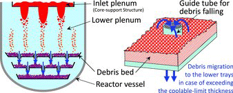
The power density in the debris-bed can be derived from decay heat and criticality. Since the coolable thickness of debris bed evaluated by the Lipinski model [Citation24,25] is less than the critical thickness, only the coolability is considered here as the safety requirement and the criticality is not further discussed. The coolability of the debris bed is strongly affected by its condition such as thickness, porosity, particle diameters and the amount of discharged fuel/steel from core region, etc. In order to achieve the stable/effective cooling of debris bed with decay-heat removal, its thickness should be suppressed below the coolable limit by the enhancement of debris dispersion. For this purpose, the multi-layer debris tray (see ) is introduced to the JSFR design, on which the debris will migrate from the upper-most tray to the lower tray in cases where the coolable-limit thickness is exceeded. The feasibility of this design concept should be further confirmed through performance tests in the future.
4.4.3. Coolability evaluation by DEBNET
The coolability of the debris bed under the typical debris distribution was evaluated by preliminary analyses using the DEBNET code, taking into account the natural circulation of the sodium coolant and the DHRS operation.
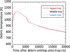
The DEBNET code [Citation26] is validated based on the debris cooling tests in Sandia National Laboratory. In the present analyses, it was assumed that 100% of the fuel inventory would be migrated onto the multi-layer debris tray. This is a conservative assumption because the fuel discharged upward by FAIDUS and the fuel remaining in core will be stably cooled in the upper-plenum and disrupted core regions, respectively. In order to demonstrate the feasibility of multi-layer debris tray to achieve stable cooling, it was assumed that the migrated/fragmented fuel would be shared among the three trays of the multi-layer debris tray in equal thickness. The temperature transient of the debris bed on three trays obtained by DEBNET is shown in . As shown in the figure, the highest debris-bed temperature among the three trays would be ensured to be below the boiling point of the sodium coolant. Even including the uncertainty in the amount of fuel discharged from the core region, stable cooling of debris-bed would be achieved under the assumption of the equitable debris distribution among the three trays derived by the design optimization of multi-layer debris tray.
4.4.4. Evaluation results and future issues
The preliminary evaluation by DEBNET code suggests that the relocated core materials would be stably cooled in the reactor vessel by fragmentation and debris-dispersion on the multi-layer debris tray, and the thermal boundary failure due to the incompleteness of stable cooling could be avoided by the installation of the multi-layer debris tray. In order to specify the detailed design of the multi-layer debris tray and to demonstrate its performance in suppressing the debris thickness below the coolable limit, we are planning a series of confirmation tests in the future. For the design study of the multi-layer debris tray, the sedimentation and accumulation behavior onto debris trays should be further clarified to reduce the uncertainty of feasibility estimation. In addition, the effectiveness of self-leveling behaviors [Citation27] on stable cooling for the debris bed has also been investigated in order to give further robustness to the present CDA scenario from the viewpoint of achieving IVR.
5. Conclusions
The CDA scenario was evaluated against the ULOF case for JSFR. The factors leading to IVR failure were identified by phenomenological diagrams, and the effectiveness of design measures to avoid IVR failure was investigated based on related experiments and analytical simulations. This is an unprecedented approach to the construction of a CDA scenario, and is an effective method to objectively investigate the factors leading to IVR failure and the design measures against them. The event progressions, in particular for the material-relocation and heat-removal phases, were quantitatively evaluated for the first time in the world. It was concluded that mechanical/thermal boundary failures could be avoided by adequate design measures, and a clear vision for achieving IVR was obtained. In addition, the issues for ensuring the further robustness of IVR were identified.
Acknowledgements
The authors would like to express their sincere gratitude to Messrs K. Takahashi, T. Yasumatsu, M. Mizuno, S. Hosono, M. Sugaya and T. Kondo of NESI Inc., for their technical contribution on computational analyses, which played important role in the evaluation of the CDA scenario.
References
- Sagayama Y. Launch of fast reactor cycle technology development project in Japan. Paper presented at: Proc. Global 2007; 2007 Sep 9–13; Boise, ID. [CD-ROM].
- Nakanishi S, Hosoya T, Kubo S, Kotake S, Takamatsu M, Aoyama T, Ikarimoto I, Kato J, Shimakawa Y, Harada K. Development of passive shutdown system for SFR. J Nucl Technol. 2010;170(1):181–188.
- Ichimiya M, Mizuno T, Kotake S. A next generation sodium-cooled fast reactor concept and its R&D program. J Nucl Eng Technol. 2007;39(3):171–186.
- Kotake, S, Sakamoto Y, Mihara T, Kubo S, Uto N, Kamishima Y, Aoto K, Toda M. Development of advanced loop-type fast reactor in Japan. J Nucl Technol. 2010;170(1):133–147.
- Niwa H. Safety implications of the EAGLE experimental results for the FaCT project. Paper presented at: Proc. Int. Conf. Nuclear Power of Republic Kazakhstan; 2007 Sep 3–5; Kurchatov, Kazakhstan. [CD-ROM].
- Konishi K, Kubo S, Sato I, Koyama K, Toyooka J, Kamiyama K, Kotake S, Vurim AD, Gaidaichuk VA, Pakhnits AV, Vassiliev YS. The EAGLE project to eliminate the recriticality issues of fast reactors – progress and results of in-pile tests. Paper presented at: Proc. NTHAS5; 2006 Nov 26–29; Jeju, Korea. [CD-ROM].
- Sato I, Tobita Y, Konishi K, Kamiyama K, Toyooka J, Nakai R, Kubo S, Kotake S, Koyama K, Vassiliev Y, Vurim A, Zuev V, Kolodeshnikov A. Safety strategy of JSFR eliminating severe recriticality events and establishing in-vessel retention in the core disruptive accident. J Nucl Sci Technol. 2011;48(4):556–566.
- Sato I, Yamano H, Tobita Y. Development of severe accident evaluation technology (level 2 PSA) for sodium-cooled fast reactors (2). Identification of dominant factors in initiating phase of unprotected events. Paper presented at: Proc. ICAPP’09; 2009 May 10–14; Tokyo, Japan. [CD-ROM].
- Konishi K, Toyooka J, Kamiyama K, Sato I, Kubo S, Kotake S, Koyama K, Vurim AD, Gaidaichuk VA, Pakhnits AV, Vassiliev YS. The results of a wall failure in-pile experiment under the EAGLE project. Nucl Eng Des. 2007;237(22):2165–2174.
- Sato I, Lemoine F, Struwe D. Transient fuel behavior and failure condition in the CABRI-2 experiments. Nucl Technol. 2004;145(1):115–137.
- Onoda Y, Fukano Y, Sato I, Marquie C, Duc B. Three-pin cluster CABRI tests simulating the unprotected loss-of-flow accident in sodium-cooled fast reactors. J Nucl Sci Technol. 2011;48(2):188–204.
- Rothman AB. TREAT experiments with irradiated fuel simulating hypothetical loss-of-flow accidents in large LMFBRs. Paper presented at: Proc. Int. Mtg. Fast Reactor Safety Technology; 1979 Aug 19–23; Seattle, WA. p. 924.
- Bauer TH, Morman JA, Hill DJ, DeVolpi A, Goldman AJ. Post-failure material movement in the PFR/TREAT experiments. Paper presented at: Proc. Int. Mtg. Fast Reactor Safety and Related Physics; 1986 May 12–16; Guernsey, UK. p. 1647.
- Kondo S, Morita K, Tobita Y, Shirakawa N. SIMMER-III: an advanced computer program for LMFBR severe accident analysis. Paper presented at: Proc. ANP’92; 1992 Oct 25–29; Tokyo, Japan. IV, p. 40.5-1.
- Tobita Y, Kondo S, Yamano H, Morita K, Maschek W, Coste P, Cadiou T. The development of SIMMER-III, an advanced computer program for LMFR safety analysis and its application to sodium experiments. Nucl Technol. 2006;153(3):245–255.
- Toyooka J, Endo H, Tobita Y, Ninikata H. A study on mechanism of early failure of inner duct wall within fuel subassembly with high heat flux from molten core materials based on analysis of an EAGLE experiment simulating core disruptive accidents in an LMFBR. Nihon-Genshiryoku-Gakkai Shi (J At Energy Soc Jpn). 2013;12(1):50–66. Japanese.
- Kamiyama K, Tobita Y, Suzuki T, Matsuba K. Development of an assessment methodology for the molten-fuel discharge behavior in the core disruptive accident of sodium-cooled fast reactors. Paper presented at: Proc. ISSNP2013; 2013 Nov 22–24; Beijing, China.
- Kamiyama K, Konishi K, Sato I, Toyooka J, Matsuba K, Zuyev V, Pakhnits A, Vurim A, Gaidaichuk V, Kolodeshnikov A, Vassiliev Y. Experimental studies on upward fuel discharge during core disruptive accident in sodium-cooled fast reactors. Paper presented at: Proc. NTHAS8; N8P1035; 2012 Dec 9–12; Beppu, Japan.
- Petersen JF. TAC2D, a general purpose two-dimensional heat transfer computer code, user's manual: USAEC Report, GA-8868, Gulf General Atomic. San Francisco (CA): US Atomic Energy Commission; 1969.
- Saito M, Sato K, Imahori S. Experimental study on penetration behaviors of water jet into freon-11 and liquid nitrogen. Paper presented at: Proc. ANS National Heat Trans. Conf.; 1988 Jul 24–27; Houston, TX. pp. 173–183.
- Kondo Sa, Konishi K, Isozaki M, Imahori S, Furutani A, Brear DJ. Experimental study on simulated molten jet-coolant interaction. Nucl Eng Des. 1995;155(1–2):73–84.
- Magallon D, Hohmann H, Schins H. Pouring of 100-kg-scale molten UO2 into sodium. Nucl Technol. 1992;98:79–90.
- Matsuba K, Kamiyama K, Konishi K, Toyooka J, Sato I, Zuev V, Kolodeshnikov A, Vasilyev Y. Experimental study on material relocation during core disruptive accident in sodium-cooled fast reactors – results of a series of fragmentation tests for molten oxide discharged into a sodium pool. Paper presented at: Proc. NTHAS8, N8P1038, 2012 Dec 9–12; Beppu, Japan. [CD- ROM].
- Lipinski RJ. A coolability model for post-accident nuclear reactor debris. Nucl Technol. 1984;65(1):53–66.
- Mitchell GW, Ottinger CA, Meister H. The D10 experiment: coolability of UO2 debris in sodium with downward heat removal (NUREG/CR-4055 SAND84-1144 R7). Washington, DC: Office of Nuclear Regulatory Research, US Nuclear Regulatory Commission; 1984.
- Koyama K, Yamada Y, Hayakawa S, Watanabe M, Watanabe O. Development of severe accident evaluation technology (level 2 PSA) for sodium-cooled fast reactors (4). Identification of dominant factors in core material relocation and heat removal phases. Paper presented at: Proc. ICAPP’09; 2009 May 10–14; Tokyo, Japan. [CD-ROM].
- Cheng S, Yamano H, Suzuki T, Tobita Y, Nakamura Y, Zhang B, Matsumoto T, Morita K. Characteristics of self-leveling behavior of debris beds in a series of experiments. Nucl Eng Technol. 2013;45:323–334.

