Abstract
Severe accident analysis for Small Break (SB), Middle Break (MB), and Large Break (LB) Loss-Of-Coolant Accident (LOCA), Station Black Out (SBO), Total Loss-Of-Feed-Water (TLOFW) was performed and effectiveness of Reactor Coolant System (RCS) depressurization strategies of OPR1000 was analyzed using MELCOR 1.8.6 code. Required injection flow rate has been derived using Core Exit Temperature (CET) information obtained from MELCOR calculation and a simple model and corresponding coolability map have been suggested to assist effective operator action. The depressurization strategies using secondary Atmospheric Dump Valve (ADV) for SBLOCA, pressurizer Safety Depressurization System (SDS) for SBO and TLOFW were introduced in 5 min since the initiation of Severe Accident Management Guidance (SAMG). Respective mitigation strategy employed leads to significant delay of the reactor pressure vessel failure and RCS pressure at Reactor Pressure Vessel (RPV) failure was lower than the SAMG target pressure of 2.86 MPa. Thus, possibility of High Pressure Melt Ejection (HPME) and impair of containment building is expected to avoid effectively. Using CET information obtained from MELCOR calculation, a simple model and a coolability map for the required injection flow rate were developed for recovery of core coolability. It is suggested that the coolability map based on MELCOR calculation results may provide decisive and intuitive information to operators for more effective safety management.
1. Introduction
The Fukushima Daiichi nuclear power plant accident occurred in March 2011 has promoted relevant researches aiming for development of more rigorous prediction methodology and establishment of systematic accident mitigation strategies. Due to the nature of complexity and uncertainty of the severe accident phenomena, however, comprehensive prediction and understanding of the severe accident still open a lot of areas to explore. In the standpoint of successful severe accident mitigation strategies, they necessitate effective operator actions established through validated analysis and practice. In particular, successful operator actions may delay or prevent Reactor Pressure Vessel (RPV) and containment building failures. With the acknowledged defense-in-depth philosophy, concept of severe accident management is to focus on preventing and terminating core damage, maintaining the integrity of containment building, and minimizing release of radionuclides [Citation1]. During the anticipated transient events, the nuclear power plant is operated under the Emergency Operating Procedure (EOP). The operation phase shifts to the Severe Accident Management Guidance (SAMG) when the Core Exit Temperature (CET) reaches a set point. Since the accident features are very specific to the type of nuclear power plant, SAMG is developed by owners group such as Organisation for Economic Co-operation and Development/Nuclear Energy Agency (OECD/NEA), Combustion Engineering Owners Group (CEOG), and Westinghouse Owners Group (WOG). In WOG SAMG, CET = 922 K is set as the SAMG entry point, which indicates the reactor core state is uncovered by 75% [Citation2].
Established method of Probabilistic Safety Analysis (PSA) provides initial basis for assessing the core damage frequency, from which relative importance of respective Design Basis Accident (DBA) and Beyond DBA (BDBA) can be identified. Best estimate codes such as RELAP5, TRACE, and MARS are used for the analysis of detailed progressions of the DBAs. However, these codes are inapplicable for the comprehensive analysis of the severe accident and BDBA scenarios, which are the accidents following the unmitigated DBAs with unavailable engineering safety systems. So the detailed progressions of the nuclear power plant under the severe accident are analyzed as a part of PSA Level 2. For this, it is imperative to utilize different codes dedicated to the analysis of severe accident. Several severe accident analysis codes such as MELCOR, SCDAP/RELAP5, MAAP, ASTEC, and SAMPSON have been used for power plant simulation and development and validation of accident management program [Citation3]. Comparative calculations of thermal-hydraulic models and core degradation for TMLB accident of Zion Nuclear Power Plant (NPP) were performed using MELCOR, MAAP, and SCDAP/RELAP [Citation4]. Besides, Large Break LOCA (LBLOCA) and SBO scenarios were evaluated using the same kind of codes for BWR [Citation5]. In addition, SCDAP/RELAP5 code was introduced to evaluate suitability of SAMG entry condition (CET = 922 K) set for the Optimized Power Reactor (OPR1000) by assuming the high pressure sequences accidents having high probability of transition to severe accident [Citation6]. Using the same code, Reactor Coolant System (RCS) depressurization and coolant injection strategies of SAMG were evaluated for Small Break LOCA (SBLOCA) and TLOFW scenarios [Citation7,8]. Using MELCOR 1.8.5, bleed and feed strategy of SAMG was simulated for Kuosheng BWR [Citation9]. Also cavity flooding strategy of SAMG was closely analyzed through comparison of lower head CHF correlation using MELCOR [Citation10]. Severe accident mitigation strategies such as RCS depressurization and external reactor vessel cooling were assessed for postulated SBO using MELCOR [Citation11]. As such, several severe accident scenarios have been analyzed using the state-of-the-art severe accident codes. However, there is still lack of data for improving SAMG. Especially SAMG is initiated with the reception of CET signals, which are closely monitored by the operators. Therefore, building a database of the required mitigating strategies corresponding to certain CET tendency may help the operators making the most effective decision.
The objective of this study is, therefore, first to validate the effectiveness of the employed severe accident mitigating strategies and second to figure out the required coolant injection with respect to CET tendency for postulated accident scenarios. To fulfill this, severe accident simulations of Korean OPR1000 were performed with SAMG strategy developed in 1998 [Citation12]. According to PSA results for OPR1000, it is evaluated that SB/MB/LBLOCA without Safety Injection (SI), SBO, and TLOFW scenarios bear high possibility of proceeding to a severe accident [Citation7]. Therefore, these scenarios are assessed using MELCOR 1.8.6. SBLOCA, SBO, and TLOFW scenarios are classified as high pressure sequence. Thus, RCS depressurization strategy was introduced to mitigate such high pressure sequence. RCS depressurization is expected to delay RPV failure time; however, in the long run, reliable means of coolant injection into the RCS need to be secured to terminate the accident sequence. Therefore using MELCOR calculation results, a simplified model of required flow rate with respect to CET increase rate is derived for permanent core cooling. The derived model may give the operator the decisive indication for taking further actions.
2. Simulation descriptions
2.1. MELCOR description
MELCOR is a state-of-the-art computer code, which enables to simulate the progression of the severe accidents postulated for light water reactor. Several versions of MELCOR code have been developed by SNL for plant risk assessment and source term analysis since 1982. In this study, MELCOR version 1.8.6 is utilized for fulfillment of addressed objectives. This code is to treat the entire spectrum of severe accident phenomena, including reactor coolant system and containment thermal-hydraulic response, core heat-up, degradation and relocation, and fission product release and transport, in a unified framework for both PWR and BWR [Citation13,14]. MELCOR code is mostly used by regulatory body and academic researchers to evaluate strategies for severe accident mitigation and to simulate detailed features of severe accident sequences [Citation15–20]. In Korea, for a successful severe accident management, an AtomCARE system has been developed for collection of SAMG variables connecting plant monitoring program with MELCOR [Citation21]. In addition, a RISARD system based on risk informed severe accident diagnosis and prognosis utilizes MELCOR code results to build up a database [Citation22].
Computer code of severe accident is classified as fast running integral codes, detailed codes, and special codes depending on the purpose. In general, MELCOR is utilized as fast running integral code, which is used to support PSA Level 2 analyses and for the development and validation of accident management program. Although MELCOR can be considered as detailed codes if the calculation is based on extensive nodalization and detailed model options [Citation1], our simulation results are relevant to integral code.
Regarding the error of MELCOR prediction, MELCOR code implements a lot of correlations and empirical models to simulate the severe accident. Thus, it is challenging to assess the prediction error of the calculation results within the scope of this work. To confirm MELCOR modeling methodology, however, steady state calculation results of OPR1000 were compared with the normal operating condition published in FSAR and the results are reported in the following section. For the sake of error analysis to the reviewer's comment, however, the best way may be to perform a statistical analysis with abundant experimental data or to compare with relevant experimental data, which are unavailable as of now. However, considering the current study has the highest priority for developing an intuitive model useful for accident management, current MELCOR calculation results are expected to be sufficient for supporting our model.
2.2. Features and MELCOR input mode of OPR1000
The reference nuclear power plant at current interest is Korean OPR1000, which consists of 2 loops of nuclear steam supply systems. It is an evolutionary design of Combustion Engineering (CE) PWR, whose nominal electrical output is 1000 MWe. Core power is 2815 MWth and cladding material is ZIRLOTM. shows the comparison of the operating conditions and steady state calculation results of OPR1000. Nominal operating conditions of OPR10000 are available in the Final Safety Analysis Report (FSAR) [Citation23].
Table 1. Design value and steady-state condition of OPR1000.
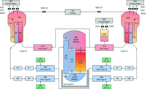
shows MELCOR nodalization for input model of OPR1000. The input model consists of a core (control volume (CV) 170), a downcomer (CV 130), a lower plenum (CV 150), a upper plenum (CV 260), four cold legs (CV 380, 390, 480, 490), two hot legs (CV 310, 410), a pressurizer (CV 500), two steam generators (CV 330, 337, 600, 610, 430, 437, 700, 710), and four safety injection tanks (CV 382, 392, 482, 492). The Safety Injection Tanks (SITs) are identical to the accumulators of Westinghouse type PWR. SITs are activated passively when RCS pressure decreases to 4.3 MPa. The pressurizer is equipped with two Safety Depressurization System (SDS) valves and pressurizer safety relief valve (PSRV). PSRV opening point is the RCS pressure of 17.24 MPa and the closing point is 14.1 MPa. SDS valves and PSRV are directly connected to the containment for conservative simulation. Containment is dived into four volumes of dome, inner shell, annulus, and cavity.
The secondary side of the steam generator includes Main Steam Isolation Valves (MSIVs), Main Steam Safety Valves (MSSVs), 8 Condenser Dump Valves (CDVs) or 4 CDVs/loop, and 4 Atmospheric Dump Valves (ADVs) or 2 ADVs/loop. MSIVs are closed when signal of reactor trip occurs. MSSVs are passively operated above 8.6 MPa of SG pressure. On the other hand, CDVs and ADVS are opened by operator action.
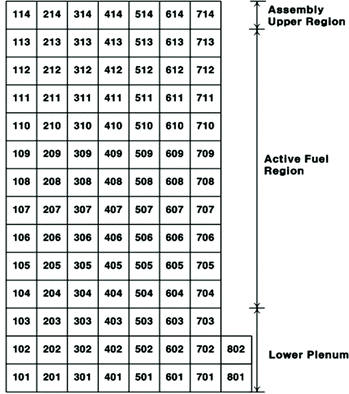
shows the core nodalization for MELCOR calculation. The core is divided into 7 radial rings and 14 axial levels. The lower plenum consisting of eight radial rings is from 1st axial level to 3rd axial level. The active fuel region is from 4th axial level to 13th axial levels. Fourteenth axial level of core cell models upper region of fuel assembly. The lower plenum allows seven penetrations and hemispheric lower head type is optioned.
Unlike the famous best estimate codes such as RELAP, MARS, and TRACE, no specific nodalization of a system is prescribed for the MELCOR. So a recent severe accident study using MELCOR by Song et al. [Citation11] utilized the almost identical nodalization to the current plant nodalization. Rather, the nodalization used in the current study has been improved in terms of dedicated upper plenum (CV190) for simulating the appropriate CET. So that more accurate CET can be calculated during the simulation.
2.3. Severe accident management guidance strategy for accident mitigation
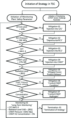
When a reactor trips or DBA occurs, EOP is adopted for recovery of stable reactor state. The shift point from EOP to SAMG states is when CET reaches 922 K. The objectives of SAMG are different from that of EOP. The main goals of SAMG are to prevent RPV failure, containment building failure, and release of radionuclides into environment. SAMG has been developed by owners group such as WOG, CEOG, and OECD/NEA. In Korea, SAMG for OPR1000 has been developed through the individual plant examination, PSA, technical basis report of EPRI, NRC reports, and research results related to SAMG in light of WOG SAMG [Citation24]. Total seven mitigation strategies are suggested for severe accident management and shows the schematic flow chart of the proposed SAMG strategies. Technical Support Center (TSC) is launched in a situation of transition EOP to SAMG. TSC takes an action for accident mitigation using described strategies in SAMG [Citation12]. The strategies are performed using several measurable parameters such as steam generator water level, RCS pressure, CET, and containment water level. Accordingly, operators have to monitor behavior of these parameters very closely. SAMG is terminated if the parameters satisfy the fixed conditions indicating that reactor state is back to the coolable state.
presents the detailed objectives and usable equipment for achieving the addressed objectives of the seven mitigation strategies. Migation-01, 02, and 03 are deemed as in-vessel mitigation strategies, whereas Mitigation-04 is related to in-vessel retention of a molten core through cavity flooding. Mitigation-05, 06, and 07 play a role in preventing the fission product release and hydrogen explosion. It should be noted that there are some differences between strategies of EOP and that of SAMG. Especially, in SAMG, the mitigation strategy for prevention of RPV creep failure and High Pressure Melt Ejection (HPME) can be fulfilled by RCS depressurization strategy, which falls into the category of Mitigation-02. Therefore, Mitigation-02 could be performed without high pressure safety injection (HPSI) or low pressure safety injection (LPSI). On the other hand, RCS depressurization performed during EOP will be feasible only if safety injections of HPSI or LPSI are available. Therefore, this study assumes the unavailable safety injections and thereby effectiveness of Mitigation-02 is analyzed to estimate the delay time, which is the time for securing the safety injection.
Table 2. Severe accident mitigation strategies of SAMG.
3. Results and discussion
Total eight cases were performed using MELCOR 1.8.6. Among these, five cases of SB/MB/LBLOCA, SBO, and TLOFW were simulated as base cases. A cold leg break has been assumed for all LOCA scenarios. The break size of SBLOCA, MBLOCA, and LBLOCA is 1.35, 6, and 10 inches, respectively. Three cases were introduced for RCS depressurization strategies. The depressurization strategies using secondary ADV were performed for SBLOCA case regardless of the available SDS in the pressurizer. In the case of SBO, SDS valve opening is assumed to be taken by DC battery and seal leakage of reactor coolant pump has not been considered. For TLOFW case, main feed water and Auxiliary Feed Water (AFW) are unavailable and opening of 1 SDS valve is considered. As mentioned earlier, safety injection is assumed unavailable for all cases. MELCOR simulations continued till the occurrence of RPV failure.
3.1. Base cases
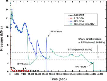
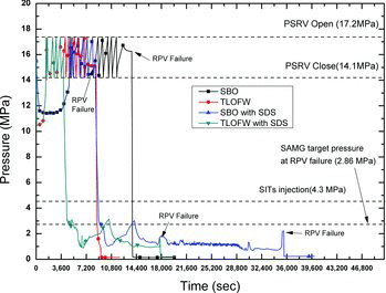
shows MELCOR results for the base cases without any operator actions aiming for accident mitigation. The accidents were initiated at time = 0 by receiving a reactor trip signal from the pressurizer for LOCA, the loss of power signal for SBO, and steam generator signal for TLOFW. SBO and TLOFW scenarios are typically categorized as high pressure sequence, in which PSRV opens passively on account of high RCS set point. With the unavailable emergency core cooling system and secondary side cooling, CET reaches the SAMG entrance point. The reactor core is then degraded due to insufficient core cooling and the molten core is relocated to the lower plenum. RPV failure occurs by penetration or creep-rupture in the cases of SBO and TLOFW. SITs are passive devices of injecting water, which is actuated by RCS pressure set point of 4.3 MPa. Through the simulation results, it is evaluated that SITs are unavailable for SBO and TLOFW cases until occurrence of RPV failure due to high pressure. In the case of SBLOCA, however, SITs are actuated after molten pool formation. In the cases of MBLOCA and LBLOCA, SITs are actuated shortly after the reactor trip and RCS pressures at the RPV failure are estimated as 0.38 and 0.2 MPa, respectively. On the other hand, RCS pressures at the time of RPV failure are estimated as 7.89, 16, and 15 MPa in the cases of SBLOCA, SBO, and TLOFW, respectively. Since the pressure at the time of RPV failure is higher than SAMG target pressure of 2.86 MPa, there exists a possibility of HPME phenomenon. The available time for in-vessel retention strategy of SAMG was averagely 5300 sec except for that of SBLOCA case, which was approximately 9800 sec.
Table 3. Sequences of base accidents.
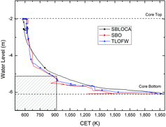
As mentioned earlier, SAMG is initiated when CET reaches 922 K, which is the point where the core uncovery proceeds by about 75% [Citation2]. Thus, it is of importance to ascertain the logic determined for SAMG entry point before proceeding to further calculation. shows core water level with respect to CET for the base cases of SBLOCA, SBO, and TLOFW. It is expected that core water is subject to depletion with accident time evolution, where evaporation of water directly impacts the decrease of water level, generation of oxidation heat, and thereby increase of CET. As observed in , the water level matching with CET = 922 K shows about a quarter of full core height, which confirms that our MELCOR simulations are reliable.
3.2. Effectiveness of RCS depressurization
Aside from the base case results, RCS depressurization strategy was introduced for SBLOCA, SBO, and TLOFW. Operator actions were assumed to be taken in 5 min since SAMG entrance using secondary side ADV and primary side SDS. SBLOCA-ADV represents utilization of secondary AFW and ADV. Similarly, SBO-SDS and TLOFW-SDS indicate utilization of the pressurizer valves for RCS depressurization. shows the calculation results with applied SAMG mitigation actions. It is evaluated that RCS pressure at RPV failure is lower as compared to the base cases and SAMG target. The failure times delayed are estimated as 24,163, 21,845, and 9185 sec for SBLOCA-ADV, SBO-SDS, and TLOFW-SDS, respectively. The delayed failure time is 2.5–6.7 hr, during which finding a mean of safety cooling may be feasible. This result can be attributed to the effective depressurization, which makes feasible for SITs. In addition, some heat could be removed through steam generator in the case of SBLOCA-ADV. Since the pressures at RPV failure are all lower than SAMG target value of 2.86 MPa, direct containment heating by HPME is expected to be mitigated successfully.
Table 4. Sequences of accidents with depressurization strategies.
shows RCS pressures for LOCA scenarios. It makes sense that RCS pressure in the beginning of accident sequence decreases more rapidly for MBLOCA and LBLOCA as compared to SBLOCA. Of interest is the case of SBLOCA-ADV, in which RCS pressure decreases more rapidly at about 9000 sec as compared to SBLOCA. This is due to the operation of secondary feed and bleed, which lowers RCS pressure below SITs actuation set point of 4.3 MPa. In the case of SBLOCA, RCS pressure is reduced below SITs actuation point at about 13,100 sec, at which the accident has been fully progressed and injected cold water quenches the overheated fuels and core structure. Thus, injected water is vaporized very rapidly and RCS is pressurized subsequently. Then the elevated RCS pressure deactivates SITs and RPV failure eventually occurs. In the case of SBLOCA-ADV, however, RCS pressure is maintained in a range of 2 MPa to 5 MPa through SITs actuation. At RPV failure, RCS pressure is estimated below SAMG target pressure, 2.86 MPa.
shows RCS pressure of SBO, SBO-SDS, TLOFW, and TLOFW-SDS. In the cases of SBO and TLOFW, fluctuations of RCS pressure are repeated within a range of PSRV open and close set point until the occurrence of RPV failure. RCS pressures at RPV failure are evaluated as 16 and 15 MPa for SBO and TLOFW, respectively. Therefore, HPME is predicted at RPV failure, which is caused by creep-rupture. On the other hand, sharp pressure declines are achieved for SBO-SDS and TLOFW-SDS with the help of RCS depressurization strategies. RCS pressures are maintained below SAMG target pressure till the occurrence of RPV failure, which suggests that the HPME can be prevented effectively.
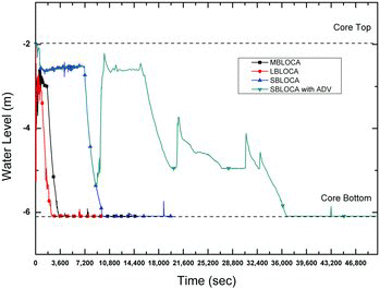
shows the core water levels for all LOCA scenarios. In the cases of MBLOCA and LBLOCA, core inventory is shortly filled with coolant of SITs in the beginning of the accident. As well for SBLOCA, although SITs were actuated before RPV failure, injection of the SITs barely affects recovery of core inventory. Of interest is the prolonged RPV failure sequence with help of ADV for SBLOCA-ADV. It is observed that actuation of ADV lowers RCS pressure and gives a chance for SITs and thereby the core inventory is refilled, which may lead to the effective delay of RPV failure.
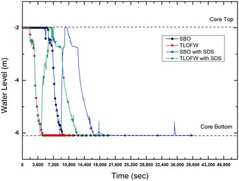
In , SBO and TLOFW base cases show the core dry-out without the recovery due to condition of high pressure. On the other hand, for SBO-SDS and TLOFW-SDS cases, the core inventory was recovered by SITs. Since then core cooling has proceeded by injected water for a while but the core is eventually dried out because of outflow through pressurizer valves.
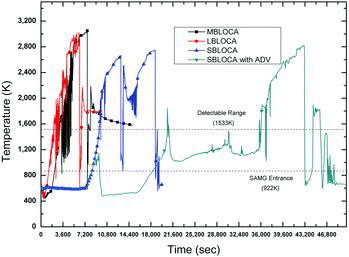
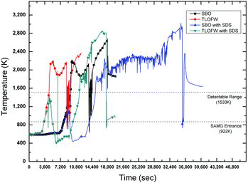
and show CETs for all LOCA scenarios and all SBO and TLOFW scenarios, respectively. In general, the tendency of CET represents state of core heat up. As core inventory decreases by discontinuity of RCS heat removal, CET increases and reaches to SAMG entry point of 922 K. Since then, oxidation heat is increasingly generated by zircaloy cladding-steam reaction. From the calculation results, it is assessed that oxidation reaction is accelerated when CET reaches 1300 K. Beyond CET = 1533 K, which is a maximum detectable range of thermocouple for OPR1000, increasing rate of CET is significantly accelerated. In the cases of SBLOCA-ADV, SBO-SDS, and TLOFW-SDS, increasing tendency of CET is reversed with help of depressurization and CET decreases below 922 K. In the meantime, core heat is removed by steam generator and coolant through SITs actuation for a while but with depletion of SITs and continuous outflow through the cold leg break for SBLOCA and the pressurizer valves for SBO and TLOFW, CET increases again and reaches above 2000 K.
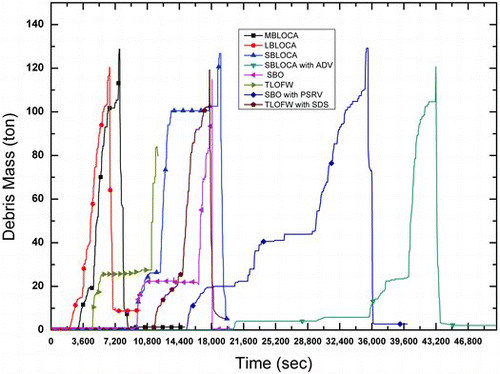
shows the debris mass of the core. The core degradation first initiates near 1150 K to 1400 K of CET. As CET increases above 1533 K, the core degradation becomes accelerated. If RPV failure occurs, debris mass of the core decreases due to ejection into the reactor cavity. The time from SAMG entrance to the detectable range of CET = 1533 K is about 12–16 min for the explored cases. Therefore, proper mitigation of accident sequence should be performed during this time interval to delay or terminate the accident.
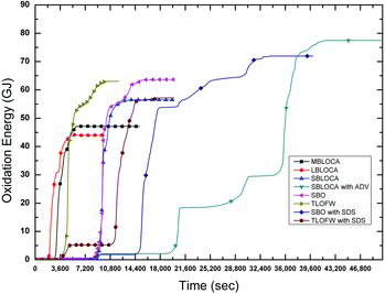
shows the accumulated oxidation energy generated during the core degradation. In SBLOCA-ADV and SBO-SDS cases, generation of oxidation heat is much more than the other cases, which implies that more hydrogen is generated in this specific case. This may be attributed to the fact that there are a plenty of steam available for oxidation reaction because coolant has been injected for a long time. In case of SBO and TLOFW, generation of oxidation heat is quite substantial because of scarce loss of core inventory.
No detailed analysis about the accident progression after the reactor vessel failure has been performed because this study focuses on the in-vessel retention feature by introducing RCS depressurization strategy rather than ex-vessel retention and related accident progress. So the MELCOR simulation has been performed until RPV failure and main interests are behavior of RCS pressure, core water level, and delay of RPV failure. Nonetheless, containment pressures at the time of RPV failure were estimated and they increase up to 0.2 MPa, which is lower than SAMG termination condition of containment pressure.
3.3. Application of MELCOR calculation for effective operator action
The objectives of coolant injection are to prevent and delay RPV failure through removal of accumulated heat and thereby to decrease radionuclides release into containment. Coolant injection into RCS is mightily important action for termination and mitigation of the postulated accidents. To minimize oxidation heat and hydrogen generation, the injection rate needs to be carefully determined using SAMG variables and available safety grade facilities. As shown in the previous results, oxidation heat can be generated substantially in SBLOCA-ADV case. Although calculation with safety injection into RCS is not considered in this study, minimum injection rate may be derived from the calculation results using information of CET with conservative assumptions. CET is generally credited as the most important monitoring parameter for accident management because the increasing trend of CET indicates the core heat-up and insufficient core cooling [Citation2].
3.3.1 Simple model for coolant injection
Core melt is caused by oxidation reaction of zircaloy cladding with high temperature steam. It is reported that oxidation energy of 5.797 × 10⁶ J per unit zircaloy mass is generated for Zircaloy-H2O reaction in reference temperature 298.15 K. In addition, the energy of 1.2065 × 10⁷ J per unit zircaloy mass is generated for Zircaloy-O2 reaction [Citation14]. In order for recovery of coolable core state, decay heat and oxidation heat have to be removed through sufficient safety injection. Therefore, total heat generation in the core is calculated using the following equation considering decay heat and oxidation heat:
(1) where qde is decay heat and qox is oxidation heat. In order to estimate the contribution of oxidation heat to CET increase, it is assumed that CET increase is related to oxidation heat generation given the specific range between oxidation temperature and detectable temperature. Then oxidation heat can be formulated as the following equation:
(2) where Eox is total oxidation energy generable during the entire accident sequence. TR is the range of CET for possibility of oxidation reaction until maximum detectable range. In other words, TR is the difference between maximum detectable CET and CET of oxidation starting point.
is increasing rate of CET. Calculated oxidation heat is considerably conservative because Eox is the oxidation energy occurs during the assumed CET range. Then qtot should be removed for successful core cooling. Required volumetric flow rate for core cooling is obtained as
(3) where hg is specific enthalpy of saturated steam and hinj is specific enthalpy of injected coolant. It is assumed that injection coolant reaches saturation state right away. Vcore is volume of core and tfill is recovery time of core inventory. This term is considered for the purpose of maintaining core water level.
A rationale for choosing CET as a key variable for this simple model can be explained as follows. Due to limited time for operator's action under the postulated severe accident, immediate- and short-term actions are needed and relevant strategies are constructed in the SAMG. In this situation, pre-calculated graphs or simple formulas should be developed to avoid the need to perform complex calculation. This is so-called “Computational Aids (CAs)”. In this way, estimation of injection flow rates needs for removing decay heat and oxidation heat of core with simplified assumptions [Citation1]. Since CET is the most important and reliable parameter for accident management, CET is a key variable and provides crucial information for the flow rate calculation [Citation2]. Increasing tendency of CET is a direct result of the core heatup and insufficient core cooling. Utilization of CET is classified as quantifying subcooling margin, detecting loss of subcooling margin, detecting onset of superheated conditions, quantifying amount of superheat, and determining that core has been successfully re-covered and cooled following an event in which core damage has occurred. In addition, heatup rate of cladding temperature is similar to the rate of the CET increase [Citation2]. For this reason, the CET readings provide crucial information for understanding accident progression and operator's proper mitigation action. In the real accident situation, other variables in the plant should be supplemented for investigation of accident progression and mitigation, for example, Reactor Vessel Level Instrumentation System (RVLIS), Ex-Vessel Neutron Detectors, and steam generator water level, to mention a few. As far as the decision of safety injection flow, however, CET information plays a key role in assisting such decision.
3.3.2 Coolability map for operator action using simple model and MELCOR results
Using EquationEquation (3)(3) , safety injection flow rate for core cooling is calculated using output data from MELCOR calculation. Some conservative assumptions are introduced. Constant decay heat value of 30 MW is used assuming 2 hr since the reactor trip. Specific enthalpy of steam evaluated at 1 MPa and specific enthalpy of injection coolant at 333 K were used for the calculation. Since specific enthalpy of steam is weakly dependent on pressure, the RCS pressure hardly influences calculation results of the mass flow rate. The recovery time (tfill) of core inventory is assumed 45 min, which is the typical time for refilling the core inventory up to the top core of OPR1000. To utilize increasing rate of CET
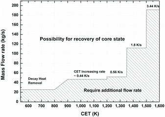
from MELCOR results, the slope of CET increase is obtained in the range from 900 K to 1533 K because oxidation heat starts to generate when CET = 900 K. In addition, the maximum detectable CET measured by K-type thermocouples is 1533 K in OPR1000. TR is difference between the value of 900 K and 1533 K. Several slopes of CET increase are calculated from MELCOR results according to the respective temperature ranges of CET = 900–1200 K, 1200–1350 K, 1350–1500 K, and 1500–1533 K. Corresponding CET increase rates are estimated as 0.44, 0.56, 1.8, and 3.44 K/sec, respectively. Total oxidation energy of 7.7 × 10¹⁰ J is the maximum value calculated by assuming complete oxidation and thus is used for conservativeness.
As a result, required injection mass flow rate with respect to CET, so called coolability map, is evaluated in the five CET intervals. represents a resulting coolability map for safety injection advising operators’ action. If the coolant injection falls into the shaded area, additional injection flow rate will be required to maintain the core coolable. If safety injection flow is more than the step line shown in , stable core coolability is achieved. The calculated mass flow rate is higher than the necessary flow rate of current SAMG for OPR1000. As such, our calculation is regarded more conservative. A complete verification of this simple model is possible with some plant data or experimental data, which are unavailable as of now. So it is beyond scope of this work and left for future work. Nonetheless, this work proposes the initiative work utilizing the intuitive information of CET, which is directly available and deemed as the most reliable data under accident conditions. As such, the map simply and intuitively shows the required injection flow rate using CET information and the methodology introduced in the current study is expected to be helpful for operators. If coolant injection is needed under severe accident, operators only need to secure injection methods such as HPSI and LPSI associated with available inventory of refueling water tank and recirculation tank in light of the coolability map.
4. Conclusion
Severe accident analysis was performed for SBLOCA, MBLOCA, LBLOCA, SBO, and TLOFW base cases. And effectiveness of RCS depressurization strategies of OPR1000 was analyzed for SBLOCA, SBO, and TLOFW cases using MELCOR 1.8.6. Required injection flow rate has been derived using CET information obtained from MELCOR calculation and a simple model and corresponding coolability map have been suggested to assist effective operator action. Major findings can be summarized as follows:
The depressurization strategies using secondary ADV for SBLOCA, pressurizer SDS for SBO and TLOFW were introduced in 5 min since the SAMG entrance. The employed strategies lead to significant delay of the RPV failure time by 24,163 sec, 21,845 sec, and 9188 sec, respectively.
RCS pressure at RPV failure was under 2.45 MPa, 2.2 MPa, and 1.6 MPa, all of which are lower than the SAMG target pressure of 2.86 MPa. Thus, with the employed RCS depressurization strategy, possibility of HPME and impair of containment building may be avoided effectively.
The time from SAMG entrance to the detectable range of CET is estimated about 12–16 min, within which proper mitigation strategies ought to be secured.
Using CET information obtained from MELCOR calculation, a simple model and a coolability map for the required injection flow rate for recovery of core coolability were developed. It is suggested that the coolability map based on MELCOR calculation results may provide effective and intuitive information for operators.
The simple model has been developed in a more conservative way than the existing model currently implemented in OPR1000 SAMG. In the existing model, it is assumed that only partial reaction between zircaloy and steam occurs during recovery. At the best verification of our model, however, complete oxidation reaction is assumed to occur so the more oxidation heat is considered. Therefore, our simple model is more conservative and secures the more margins. A complete verification of this simple model is possible with some plant data or experimental data, which are unavailable as of now. So the complete verification of the model is beyond scope of this work and left for future work.
Finally, it is considered that the coolability map associated with the simple model is intuitive and virtual to the operators’ decision on safety injection. However, more work is needed to improve the accuracy of the MELCOR prediction and coolability map with the simple model. In the future work, although it is not an ultimate solution, a study focusing on reduction of MELCOR error will be feasible through more detailed plant nodalization and uncertainty of the implemented model with user options for various phenomena.
Nomenclature
| E | = | energy [J] |
| h | = | specific enthalpy [J/kg] |
| q | = | heat [W] |
| Q | = | mass flow rate [kg/sec] |
| t | = | time [second] |
| T | = | temperature [K] |
| = | temperature increase rate [K/sec] | |
| V | = | volume [m3] |
Subscript
| CET | = | core exit temperature |
| core | = | core |
| de | = | decay |
| fill | = | filling the reactor core |
| g | = | gas or vapor |
| inj | = | injection |
| R | = | range |
| ox | = | oxidation |
| Tot | = | total |
Greek letters
| ρ | = | density [kg/m3] |
Additional information
Funding
References
- ElBaradei M. Severe accident management programs for nuclear power plants. Vienna (Austria): International Atomic Energy Agency; 2009.
- Organisation for Economic Co-operation and Development/Nuclear Energy Agency. Core exit temperature effectiveness in accident management of nuclear power reactor. NEA/CSI/R(2010)9. Paris (France): Nuclear Energy Agency; 2010.
- International Atomic Energy Agency. Approaches and tools for severe accident analysis for nuclear power plants. Vienna (Austria): International Atomic Energy Agency; 2008.
- Vierow K, Liao Y, Johnson J, Kenton M, Gauntt R. Severe accident analysis of a PWR station blackout with the MELCOR, MAAP4 and SCDAP/RELAP5 codes. Nucl Eng Des. 2004;234:129–145.
- Wang T-C, Wang S-J, Teng J-T. Comparison of severe accident results among SCDAP/RELAP5, MAAP, and MELCOR codes. Nucl Technol. 2005;150:145–152.
- Park R-J, Hong S-W. Effect of SAMG entry condition on operator action time for severe accident mitigation. Nucl Eng Des. 2011;241:1807–1812.
- Park R-J, Kim S-B, Kim H-D. Evaluation of the RCS depressurization strategy for the high pressure sequence by using SCDAP/RELAP5. Nucl Eng Des. 2008;35:150–157.
- Park R-J, Kim S-B, Hong S-W, Kim H-D. Detailed evaluation of coolant injection into the reactor vessel with RCS depressurization for the high pressure sequences. Nucl Eng Des. 2009;239:2484–2490.
- Huang IM, Ferng YM, Wang SJ. Validation of RCS Bleed-And-Feed strategy for the SAMG of the Kuosheng nuclear power plant. Nucl Technol. 2007;160:294–306.
- Martin-Fuertes F, Martin-Valdepenas JM, Mira J, Sanchez MJ. A MELCOR application to two light water reactor nuclear power plant core melt scenarios with assumed cavity flooding action. Nucl Technol. 2003;144:34–48.
- Song JH, Huh CW, Suh N. Improvement of molten core cooling strategy in a severe accident management guideline. Nucl Technol. 2012;178:258–266.
- Korea Atomic Energy Research Institute. Development of accident management guidance for Korean standard nuclear power plant. Daejeon (Republic of Korea): Korea Atomic Energy Research Institute; 1998.
- Boyack BE, Dhir VK, Gieseke JA, Haste TJ, Kenton MA, Khatib-Rahbar M, Leonard MT, Viskanta R. MELCOR peer review. Los Alamos Report, DC92012220. Los Alamos (NM): Los Alamos National Laboratory; 1997.
- Gauntt RO, Cash JE, Cole RK, Erickson CM, Humphries LL, Rodriguez SB, Young MF. MELCOR Computer Code Manual. NUREG/CR-6119, Rev.3, SAND 2005-5713. Albuquerque (NM): Sandia National Laboratories; 2005.
- Huh C, Suh N, Park G-C. Optimum RCS depressurization strategy for effective severe accident management of station black out accident. Nucl Eng Des. 2009;239:2521–2529.
- Wang TC, Wang S-J, Teng J-T. Simulation of a PWR reactor vessel level indicating system during station blackout with MELCOR 1.8.5. Nucl Technol. 2006;156:133–139.
- Haste TJ, Birchley J, Richner M. Accident management following loss-of-coolant accidents during cooldown in a Westing two-loop PWR. Nucl Eng Des. 2010;240:1599–1605.
- Bonelli A, Mazzantini O, Sonnenkalb M, Caputo M, García JM, Zanocco P, Gimenez M. Station black-out analysis with MELCOR 1.8.6 code for Atucha 2 nuclear power plant. Sci Technol Nucl Install. 2012;620298.
- Bixler N, Gauntt R, Jones J, Leonard M. State-of-the-art reactor consequence analyses Project-Volume 1 & 2. Washington (DC): Nuclear Regulatory Research; 2012.
- Birchley J, Haste TJ, Richner M. Accident management following loss of residual heat removal during mid-loop operation in a Westinghouse two-loop PWR. Nucl Eng Des. 2008;238:2173–2181.
- Yong KY, et al. Development of the application scheme for the severe accident diagnosis/assessment code. Daejeon (Republic of Korea): Korea Institute of Nuclear Safety; 2010.
- Ahn K-I, Park S-Y. Development of a risk-informed accident diagnosis and prognosis system to support severe accident management. Nucl Eng Des. 2009;239:2119–2133.
- Korea Hydro & Nuclear Power. Shin kori 1&2 final safety analysis report. Seoul (Republic of Korea): Korea Hydro & Nuclear Power; 2008.
- Kim HC, Lee SH, Kim TH, Kim DS, Kim SC, Ryu YH. Evaluation of the status of the accident management guidelines in Korea and foreign countries. Daejeon (Republic of Korea): Korea Institute of Nuclear Safety; 2013.

