Abstract
The paper presents analytical data obtained by directly measuring samples taken at different levels of a hexagonal fuel assembly duct used in the BN-350 fast reactor. The difference between the length of the deflection arc and the width of an intact duct face displays the accumulated irradiation-creep deformation during the operation period. The deflection of the duct faces induced by the irradiation creep was analyzed, and irradiation-creep rate versus distance from the core center was analyzed for the assembly duct in the BN-350 fast reactor.
1. Introduction
In the core area of reactors, the structural materials operate under severe conditions due to the simultaneous effects of temperature, stress and radiation. Radiation causes a number of effects that reduce the lifetime of parts in the core region of reactors. Irradiation creep and swelling are two major phenomena affecting the durability of structural materials. Irradiation creep is a focus of this study. In spite of much experimental and theoretical research into irradiation creep, some issues remain unresolved. The reasons are of a technical and psychological nature: the expenses are huge, data accumulates slowly, the high radiation background adds to a negative impression and together these make such research unattractive.
Decades-long experience has shown the most informative and reliable experimental data is obtained from in-reactor tests. However, there is a problem caused by the need to run experiments for thousands of hours in reactors. In addition to the technical issues related to ensuring operation of experimental equipment, there is the expense. These factors point to the necessity of studying structural materials [Citation1–3] after their use in nuclear reactors. Attempts are underway to further develop research methods and techniques to study such materials. The challenge is the high radioactivity of materials after long irradiation; only remote methods are applicable. This issue forces one to look for means of evaluating the condition of materials on the basis of a limited set of experimental data. Such an approach reduces both the cost of experiments and health risks to a researcher (a large concern of working under high radiation levels).
One such approach is described in this article. Changes in the dimensions of a fuel assembly duct from a fast-breeder reactor (BN-350) are directly measured. Due to the fact that with time the material of a duct exposed to the high-density neutron flux in the core area itself turns into a source of radiation, any work should be conducted in ‘hot cells’ equipped with special exhaust and drainage systems and other adequate protection against emission of highly radioactive materials. The hot cell stage of study was done in Aktau, Kazakhstan. Then the samples were moved to Almaty and studied at the Institute of Nuclear Physics and the Satpayev National Technical University. The goal of studying irradiation creep of duct materials is to predict their deformation behavior over a wide range of temperature, stress and neutron flux.
2. Experimental procedure
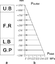
The total length of a BN-350 fuel assembly is about 4 m. The upper part of the assembly is designed for handling by collet clamps in the core area and a storage area. The lower part of the assembly has a bottom nozzle to lock into the core area. The sodium coolant moves through its lower extremity with an excess pressure of 0.55 MPa. In the upper part the output pressure of the coolant is close to 0 MPa. A large pressure gradient creates conditions for the rapid flow of liquid sodium through the core to remove heat. Special technology has been used to make these ducts: a seamless hexagonal tube with 50 mm wide sides and 2 mm thick walls. The studied fuel assembly duct was produced from 12Cr18Ni10Ti stainless steel (US analog is AISI 321) and was exposed to a final thermal–mechanical treatment of 15%–20% cold deformation followed by annealing at 800 °C for 1 hour. shows a chemical composition of the duct material.
Table 1. Chemical composition of austenitic steel 12Cr18Ni10Ti (wt.%).
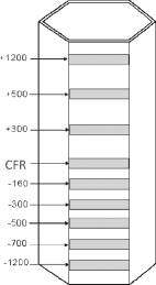
For a comprehensive study, 50×10×2 mm3 samples were cut from the CC-19 fuel assembly duct that had been in operation for a long period of time, ∼13,600 hours. The cutting of samples was carried out using abrasive wheels with intensive cooling to maintain the structure of the material. shows a pattern of sample cutting. The abbreviation CFR stands for the center of fuel region. Below the CFR are marks with a minus sign; above it with plus. The numbers indicate the distance in millimeters from the center of fuel region. shows how deflection of the duct faces was measured. It can be seen that the measurements were performed in two positions: the convex side up (a) and the convex side down (b). This method gives more accurate information on changes in the size of the faces at the height of the reactor core. In addition, measuring in two positions allows for the estimation of one more parameter of the radiation effects on construction materials – swelling. Void swelling of the duct faces was investigated using the techniques discussed, by hydrostatic weighing and by transmission electron microscopy. In this paper, the result of studies on void swelling is not considered. Before measuring the indicator reading was checked by gauge blocks. Three measurements were carried out across the width of the sample. This has improved accuracy and reduced the possibility of error. Dial gauges with a scale of 10 microns and 1 micron were used for measurement.
3. Results and discussion
schematically represents the coolant pressure along the axial length from bottom to top of the assembly. summarizes the distribution of temperature, dose and dose rates from a reactor logbook where operational conditions are recorded.
Table 2. Data on samples cut from CC-19 fuel assembly duct.
The data shows that the duct material experiences significant loads under certain conditions of reactor irradiation; in other words, a fuel assembly duct is deformed through the irradiation-creep process. Irradiation-creep results in deflection of the walls of a duct. This implies that different operational conditions on the length and width of the duct face cause different changes in shape, i.e. they cause different amounts of irradiation-creep deformation. The correctness of this assumption is confirmed by data on changes of the length of the arc made by deflection as well as their correlation with creep rate. The extent of deflection was typically calculated based on the creep deformation. The analytical method is schematically shown in .
The arc of deflection (AMB) – develops through operation in the core region of a reactor. The ACB line is the length of the original duct, and MC = f is its deflection. The following equation is applied to calculate the length of arc (Huygens’ formula) [Citation4]:
(1) where P is length of arc and l = AM = BM, L = AB = 40 mm (original length of the duct). AB and MC are known quantities. We calculate l, using the following equation:
(2) Finally, irradiation-creep strain (ϵ) can be estimated using
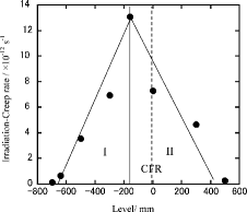
(3) The results of calculations are summarized in and plotted in , where irradiation-creep rate is represented in the dimension of sec−1 at each axial position from CFR.
Table 3. The results of measurements and calculations.
Figure 5. Correlation between the irradiation-creep rate and distance from the center of fuel region.

Two subareas are obvious in : the left side (shown as I) and the right side (shown as II) from the maximum peak. In subarea I, the irradiation-creep rate increases approaching the point of its maximum at the level marked −160 mm. The creep rate in sec−1 is generally affected by the neutron flux and stress [Citation5–7]. The neutron flux is at maximum at CFR, while the stress linearly decreases with increasing axial position. Thus, the peak of irradiation-creep rate in sec−1 shifts to the lower part from CFR.
It has been consistently shown that the irradiation-creep rate is the sum of two terms: one is independent of the swelling and the other is strongly coupled with the swelling rate. The major components of the instantaneous creep rate can be expressed by the following empirical equation [Citation8,9]:
(4) where
is an instantaneous irradiation-creep rate, σ is an effective stress, B0 is the creep compliance, D is the irradiation creep – a swelling coupling coefficient – and
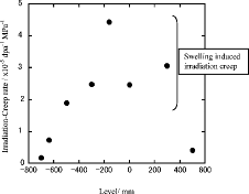
is the instantaneous volumetric swelling rate per dpa. Irradiation creep has been studied by the irradiation of pressurized tubes. Based on the most extensive review by Garner [Citation10], B0 of austenitic stainless steels is typically in the range from 0.5 to 4×10⁻⁶ dpa−1 MPa−1. shows the irradiation-creep rate in the conventional dimension of dpa−1 MPa−1.
The irradiation-creep rate analyzed in this study is one order of magnitude higher than B0 of 0.5–4×10⁻⁶ dpa−1 MPa−1, except for the bottom and top of the fuel column. This result implies that duct swelling induces the irradiation creep by the term of D at the middle of the fuel column region. The data for the fuel assembly duct used in the BN-350 at irradiation temperatures below 400 °C and at lower dose rates provides useful information relevant to irradiation creep.
4. Conclusion
The following conclusions were drawn in this research:
The deflection of the duct face in the BN-350 reactor was directly measured by a specifically designed device which provides data on plastic deformation alone by eliminating the contribution of swelling deformation. The plastic deformation values were calculated from the difference between the length of the deflection arc and the width of the original duct face.
The axial distributions of temperature, stress and damage rate were analyzed on the basis of the BN-350 reactor logbook.
It was estimated that plastic deformation of the duct deflection was affected by the neutron dose and stress, where the neutron dose reaches its peak at the center of the fuel column, while the stress decreases along the axial direction from the bottom. It was shown that maximum deformation occurred at −160 mm from the center of the fuel region.
The deflection deformation of the duct face is caused by irradiation creep under the stress and neutron dose. The irradiation-creep rates were estimated, and it was shown that those values came not only from the swelling independent term, but also swelling coupled term. The data of the fuel assembly duct used in the BN-350 duct provided useful information relevant to irradiation creep at irradiation temperatures below 400 °C.
References
- Cole JI, Allen TR, Ukai S, Mizuta S, Akasaka N, Donomae T, Yoshitake T. Swelling and microstructural evaluation in 316 SS hexagonal ducts following long term irradiation in EBR-II. Effect of irradiation on materials. In: 20th International Symposium on ASTM STP; 2003; West Conshohocken, PA. West Conshohocken (PA): American Society for Testing and Materials; 2003. p. 413–426.
- Kadyrzhanov KK, Romanenko OG, Turkebaev TE, Maksimkin OP, Kislitsin SB, Chumakov EV, Kenzhin EA, Yakovlev IL, Turubarova LG, Gusev MN, Tivanova OV, Tsai KV. Effect of irradiation on stainless steel C0.08Cr16Ni11Mo3 – material for hexagonal duct of spent fuel assembly from the BN-350 fast neutron reactor. Vol. 1. The radiation solid-state physics and materials science problems. In: Proceedings of the 4th International Conference on Nuclear and Radiation Physics; 2003 Sep 15–17; Almaty, Kazakhstan. Almaty (Kazakhstan): Institute of Nuclear Physics NNC RK; 2004. p. 58–84.
- Kadyrzhanov KK, Romanenko OG, Turkebaev TE, Maksimkin OP, Kislitsin SB, Chumaskov EV. Structure and mechanical properties of stainless steel C0.08Cr16Ni11Mo3 irradiated in fast neutron nuclear reactor BN-350. In: Proceedings of the 5th International Conference on Interaction of Radiation with Solids; 2003 Oct 6–9; Minsk, Belarus. Minsk (Belarus): Belarus State University; 2003. p. 157–159.
- Vygodsky M. Mathematical handbook: elementary mathematics. Yankovsky G, translator. Moscow: Mir Publishers; 1984. p. 282–283.
- Chumakov EV. Reactor and thermal creep of metals and alloys. Theory and experiment. Volume 2, Radiation physics. In: Proceedings of the 3rd International Conference on Nuclear and Radiation Physics; 2001 Jun 4–7; Almaty, Kazakhstan. Almaty (Kazakhstan): Institute of Nuclear Physics NNC RK; 2001. p. 510–522.
- Aitkhozhin ES, Chumakov EV. Radiation-induced creep of copper, aluminium and their alloys. J Nucl Mater. 1996;233–237:537–541.
- Aitkhozhin ES, Ibragimov Sh, Chumakov EV. Temperature dependence of the reactor creep of copper and aluminum. At Energy. 1990;69:142–145.
- Ehrlich K. Irradiation creep and interrelation with swelling in austenitic stainless steels. J Nucl Mater. 1981; 100:149–166.
- Foster JP, Wolfer WG, Biancheria A, Boltax A. Analysis of irradiation-induced creep of stainless steel in fast spectrum reactors. In: Proceedings of the European Conference on Irradiation Embrittlement and Creep in Fuel Cladding and Core Components; 1973 Nov 9–10; London, UK. London: British Nuclear Energy Society; 1973. p. 273.
- Garner FA. Irradiation performance of cladding and structural steels in liquid metal reactors. In: Frost BRT, editor. Materials science and technology: a comprehensive treatment. Vol. 10A. Weinhem: Wiley-VCH; 1994. Chapter 6, p. 419–543.


