Abstract
The Korea Atomic Energy Research Institute has developed the SMART integral reactor, and SCOPS and SCOMS were also newly developed as advanced real-time core protection and monitoring systems for SMART. SCOPS calculates the minimum DNBR and maximum LPD based on several on-line measured core state parameters, and SCOMS calculates the limiting conditions for operation variables and assists the operator in implementing the technical specification requirements for monitoring. The design features and characteristics of SCOPS and SCOMS were described. The performance of the SCOMS power distribution synthesis method was evaluated and shows negligible power distribution synthesis errors. A technically reliable uncertainty analysis method was developed, and a preliminary uncertainty analysis was evaluated. The overall analysis results are similar or more improved compared to those of cycle 1 for Younggwang units 3&4 of Korea. In particular, uncertainty factors of SCOMS are much improved because of an improvement in the power distribution synthesis and DNBR calculation algorithm. Finally, thermal margins were estimated, and the DNB overpower margin of SCOMS is large enough to accommodate a 40% required overpower margin and 15% top-tier requirement thermal margin.
1. Introduction
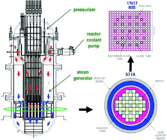
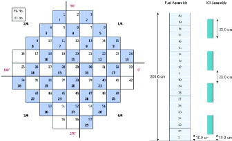
The Korea Atomic Energy Research Institute (KAERI) has developed a system-integrated modular advanced reactor (SMART) for seawater desalination and electricity generation with 330 MW thermal power. As shown in , primary reactor components, i.e. four reactor coolant pumps, a pressurizer and eight steam generators are installed inside the reactor pressure vessel, and the reactor core is composed of 57 fuel assemblies with a 17×17 fuel rod array. SMART enhances the inherent safety features by adopting such design features. SMART is operated with a low linear heat rate. Low power density reduces the fuel and clad temperatures during accidents. SMART has a large reactor coolant system volume. The large coolant volume of the reactor allows more time for safety system response in the event of accidents and more coolant is available during a small break loss of coolant accident by providing continuous cooling to protect the core. Also, SMART is designed with small penetrations at high elevation. High location of penetration increases the amount of coolant left in the reactor vessel after a small break of coolant accident. and show the core configuration and major design parameters of SMART.
Table 1. Primary design parameters of SMART.
Accordingly, the design of an advanced core protection and monitoring system was needed for the newly developed integral reactor, and SCOPS and SCOMS were developed as an on-line digital core protection and monitoring system [Citation1,2]. SCOPS calculates the minimum DNBR and maximum LPD based on several on-line measured core state parameters, such as excore neutron detector fluxes, control rod positions, pump rotational speeds, system pressure, and core inlet and outlet temperatures. The calculated value of DNBR, LPD and auxiliary trip variables is compared with the predetermined safety limited value, and a trip signal is generated, if necessary. SCOMS calculates LCO variables using measurable system parameters and assists the operator in implementing the technical specification requirements for monitoring.
Currently operated PWRs in South Korea were mostly designed by Westinghouse and ABB-CE. Each type adopts a different protection and monitoring method, i.e. an analog system and a digital system. Westinghouse plants employ an analog protection and monitoring system for Kori units 1–4 and Younggwang units 1 and 2 (YGN1&2). The thermal overpower and overtemperature delta-T protection system (OP△T and OT△T, respectively) are used to provide an analog protection against a fuel centerline melting and DNBR [Citation3]. ABB-CE developed digital computer based reactor protection and monitoring systems that have been used in YGN3&4 and Ulchin units 3&4. The CPCS provides reactor protection functions by calculating the real-time values of the DNBR and LPD based on live sensor signals [Citation4]. These calculated DNBR and LPD values are continuously compared to plant-specific trip limits. Complementing the CPCS is a digital computer based monitoring system, COLSS [Citation5]. COLSS resides on the plant computer and monitors selected technical specification related limits and alerts the operators to impending violations. As noted, these protection and monitoring methods (or codes) were developed for the conventional PWRs. So, the necessity for the development of unique core protection and monitoring systems for the integral reactor arose. SCOPS and SCOMS were developed based on conventional CPCS and COLSS; however, SCOPS and SCOMS adopted new design features and algorithms to meet the design requirement of the integral reactor SMART.
This paper describes the design features and characteristics of the newly developed SMART core protection and monitoring systems. The newly introduced 3D power distribution synthesis methodology of SCOMS is described and the performance of the algorithm is evaluated. Also, the newly developed uncertainty analysis methodology and uncertainty analysis results are explained. Finally, thermal margins for the SCOPS and SCOMS are estimated, respectively.
2. Design features and characteristics
2.1. Algorithm improvements
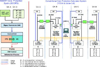
SCOPS simplifies the protection system by directly connecting the four RSPT signals to each core protection and signal transfer system between protection channels [Citation6]. The elimination of CEAC hardware was achieved by developing a new control rod assembly position indicator which has 4-RSPT instead of 2-RSPT per control rod assembly. This functional structure (4-CPC and 2-CEAC) of conventional CE-type plants, until now, has caused lots of abnormal trip generations by a transmission of improper penalty factors and by a failure of control element assembly related hardware. depicts the simplified SCOPS hardware configuration against a conventional core protection system.
A 3D power distribution synthesis method was developed using measured incore detector data and a neutronics code library [Citation7]. SCOMS adopts the method DPCM3D instead of the Fourier expansion method used in a conventional core monitoring system. The DPCM3D method produces a synthetic 3D power distribution by coupling a neutronics code and measured incore detector signals. In this method, instrumented node powers are determined from the detector powers using power-sharing factors and the uninstrumented node powers are determined using power connection factors. A coefficient library for the 3D power synthesis is functionalized as a function of burnup, core power, and control rod position. By employing a DPCM3D method, a core power distribution can be synthesized more accurately by eliminating the fitting error.
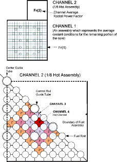
A fast-running DNBR calculation code, FAST, was developed for determining the core thermal margins of SMART [Citation8]. FAST satisfies the CPU time limit and computational robustness as a requirement of the DNBR calculation modules of SCOPS and SCOMS. FAST shows conservative results compared with the subchannel analysis thermohydraulic code. FAST reduces the computation time by reducing the number of subchannels needed in the model and by using a simplified non-iterative scheme called the prediction–correction method. The DNBR calculation algorithm of FAST was implanted in SCOPS and SCOMS without any algorithm change. shows the DNBR channel model used in SCOPS and SCOMS. In this model, the core is modeled as one fuel assembly and a 1/8 hot assembly, and a hot channel and surrounded channels are depicted as channels 4 and 3, respectively. Other channels are adopted to calculate the enthalpy transport coefficient which compensates the enthalpy distribution between a lumped channel and subchannel.
A new CHF correlation, SF-1, was developed for SMART [Citation9]. The developed correlation was applied to the DNBR calculation of SCOPS and SCOMS. Water and Freon experimental data were used in the correlation development and the SF-1 CHF correlation is expressed as
1 where q′′CHF = critical heat flux, q′′CHF, HG = critical heat flux at a high flow rate condition, q′′CHF, LG = critical heat flux at a low flow rate condition, FG = correction factor for a low flow rate condition, andFNU = correction factor for a non-uniform axial power distribution.
The SF-1 correlation was fitted by a regression technique and validated by statistical tests. The tolerance limit of the correlation can be calculated by Equation (2) and corresponds to a CHF correlation (SF-1) limit DNBR:
2 where DNBRCL is the SF-1 CHF correlation limit DNBR,
is the ratio of the measured to predicted value, k95/95 is a one-sided tolerance limit with a 95/95% confidence/probability, and sM/P is the standard deviation. The SMART top-tier requirement requires a 15% additional thermal margin, and therefore the limited DNBR was calculated as
3
4
2.2. SCOPS/SCOMS module configuration
The SCOPS design base requires that the system calculates conservative but relatively accurate values of DNBR and LPD. However, the algorithms that require sufficiently detailed calculations cannot be executed rapidly enough to provide protection for those design basis events with the most rapid approach to the specified acceptable fuel design limit. To achieve a system time response sufficient to accommodate the limiting design basis events, additional dynamic calculations of DNBR and LPD are required. The dynamic calculations must provide conservative estimates of DNBR and LPD based on the changes in the process variables between successive detailed calculations. The detailed calculations of DNBR and LPD must be separated into different programs. The SCOMS design is a little different from that of SCOPS. Because SCOMS is a non-safety system, a less restrictive time response is acceptable. SCOMS uses measured signals of the secondary system, including the turbine differential pressure as well as those of the primary system. For this reason, SCOMS can calculate LCO variables (DNBR margin, LPD margin, azimuthal tilt, and axial offset) more accurately with sufficient time and assist the reactor in maintaining plant operation within the desired operating boundary with the joining of the protection system and technical specifications.
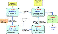
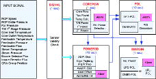
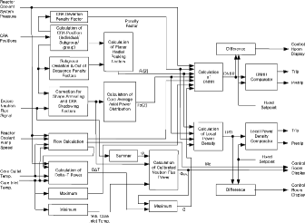
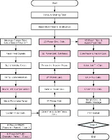
From these design bases, SCOPS and SCOMS functional modules were designed and optimized by considering the algorithm characteristics and execution time requirements. As shown in and , each module performs a unique protection or monitoring algorithm, and transmits (or receives) calculated variables to (from) each other within the allowed execution period. SCOPS and SCOMS consist of five interdependent modules. In , CRAPOS calculates penalty factors and representative control rod group positions. CORAPD synthesizes the core average and pseudo-hot-pin power distribution with the control rod position and excore detector signals. STDNBR calculates static DNBR accurately every 2 seconds. CORVAR calculates trip variables with real-time measurement signals. These trip variables are compared with the predetermined safety limit and trip signals are generated in the TRPGEN module. In , SIGVAL checks signal validity and COREPOW calculates core powers (e.g. primary, secondary, and turbine power). POWER3D synthesizes core power distribution with three dimensions and POL calculates the power operation limit related to DNBR and LPD. Finally, MARGIN computes the operating margin and initiates an alarm signal to the operator. These module structures of SCOPS and SCOMS enhance the safety and reliability of the core protection and monitoring system of SMART. and show the functional diagram and flowchart of the SCOPS and SCOMS algorithms, respectively.
3. SCOMS power distribution synthesis
As noted, the DPCM3D power distribution synthesis method is implemented in SCOMS. The DPCM3D method has been developed to synthesize core power distributions more effectively and is used as a main algorithm in on-line core supporting systems for incore management of SMART as well as SCOMS. The method produces a synthetic 3D power distribution by coupling a neutronics code and measured incore detector signals. In this section, DPCM3D is explained briefly, and the SCOMS 3D power synthesis performance for the SMART initial core is evaluated. Also, the results of a sensitivity test as a function of the number of failed detectors are presented.
3.1. DPCM3D method
In DPCM3D, each node power is determined from the power coupling coefficients (i.e. power sharing factor and power connection factor). The detected node power is determined using a power sharing factor and an incore detector power. Generally, the axial size of a detector is greater than that of an axial node, and a detector includes a few neutronics nodes. The detected node power can be reproduced from the detector power by using a power-sharing factor as Equation (5). k′ and k are axial indices for the detector and the neutronics node, and l is the radial index for the neutronics node. In addition, the superscript “d ” means the detected power.
5 where Pdl, k = detected node power of node (l, k),
= detector power of unit k′ from the incore detector signal, and
= power-sharing factor from detector k′ to node k.
The exact power-sharing factor cannot be determined if all the neutronics power of is not directly detected by using incore detectors. Therefore, an approximated power-sharing factor is introduced in the 3D power calculation based on neutronics solutions as Equation (6).
6 where
= approximated power-sharing factor, PCl, k = node power calculated by the neutronics code,
= detector power calculated by the neutronics code,
= ratio of the included size of neutronics node k to detector k′ to the whole size of detector k′ (=
),
= height of detector unit k′, and
= height of plane k included in detector unit k′.
The superscript “c” means the calculated value by the neutronics code. The usefulness of Equation (5) depends on the accuracy of the estimated .
An undetected node power can be determined using the neighboring powers and the 3D power connection factor is defined by the ratio of the power of a node (l, k) to the power average of the neighboring nodes as Equation (7).
7 where Cl, k = power connection factor at node (l, k) and Nl, Nk = number of radially and axially neighboring nodes to node (l, k).
The exact 3D power connection factor cannot be determined for the same reason as the power-sharing factor. Therefore, an approximated 3D power connection factor is introduced based on neutronics solutions as Equation (8). The accuracy of the generated power distribution also depends on the accuracy of the estimated CCl, k.
8
The governing equation for the power of node (l, k) can be written from the definition of the 3D power connection factor of Equation (7).
9
The right-hand side (RHS) of Equation (9) includes determined node powers from Equation (5) as well as undetermined node powers as Pl, k of the hand side (LHS). Equation (9) can be rewritten by moving the undetermined node powers to the LHS as follows:
10
Groups U and I mean the undetermined and detector node groups, respectively. The final governing matrix equation for the undetermined node powers can be established as
11 where A = power vector for undetected nodes, P = vector of undetected node powers, and S = source vector from detected node powers.
This equation is a fixed source problem and can be solved easily by applying an iterative scheme. The final 3D power distribution is generated by applying a normalization procedure to the solution of Equation (11).
Power coupling coefficients are prepared in advance for many different core conditions and these coefficients are functionalized as a function of the burnup, core power, and control rod position. SCOMS finds out appropriate power coupling coefficients from the library table using burnup and power control rod position data.
3.2. 3D power distribution synthesis
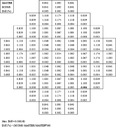
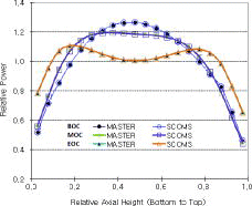
The 3D power distribution was synthesized for the SMART initial core using the coefficient library and incore detector signals. The library constants of , CCl, k, and detector signals of the rhodium self-powered neutron detector were generated from the reference power distribution of the MASTER neutronics code [Citation10]. In this calculation, it was assumed that MASTER provides reference solutions even though MASTER solutions include calculation uncertainty associated with the nuclear design methodology. – show the simulated incore detector configuration and synthesis results of the radial and axial power distributions. As can be seen, a radial power distribution error (axially integrated 2D power) shows a maximum of 0.006% at a BOC condition, which is a negligible value. Also, the synthesized axial power shapes match well with the reference shapes throughout the core lifetime. These trivial errors of radial power distribution are less than the truncation error of about 0.02%, caused by the number of digits for the power distribution and detector signals.
Also, a sensitivity test for the number of failed detectors was performed. Detector signals are made to be 0.0 (zero) compulsorily to simulate a failed detector condition, and the 3D power distribution was then synthesized with available detectors. The number of failed detectors was increased to almost a 100% failed condition. shows the computational results for 3D power synthesis errors as a function of the number of failed detectors and shows the position of the failed incore detector. Failed detectors are accumulated as the number of test cases is increased. For the most severe case (only one detector available for the source term), the maximum 3D error is less than 0.3% compared with the reference result. This demonstrates that the SCOMS 3D power synthesis algorithm is robust and less sensitive to the number of available detectors compared with the conventional COLSS algorithm. Also, SCOMS can synthesize a 3D power distribution exactly with a minimum available number of detectors. Special consideration for generating power coupling coefficients, i.e. axial neutronics node assignment versus axial detector size and position and heterogeneity of the core, helps improve the synthesis accuracy. In conventional PWRs, COLSS adopts the Fourier expansion method to generate core power distribution. COLSS generates level-averaged detector responses from available detector signals and fits the core average axial power shape. Thus, COLSS inevitably includes considerable fitting error in itself. Even though DPCM3D shows good performance in power distribution synthesis, SCOMS uses lots of incore detectors (29×4) and stops synthesizing power distribution if the number of available incore detectors is less than 75% of the total number of detectors.
Table 2. 3D power distribution synthesis errors as a function of the number of failed detectors.
Table 3. Failed detector information for 3D power synthesis error calculation.
With regard to the robustness of DPCM3D, the uncertainty of the algorithm was estimated for the various core conditions [Citation11]. The sensitivity study showed that coupling coefficients varied severely with the control rod position but smoothly with the core burnup and the core power. From the results of the study, a coupling coefficient is expressed as a function of these parameters and the data library containing the power sharing and power connection factors is generated from the neutronics code calculation. Also, it was concluded that the 3D power distribution method should consider about a 1.5% node power uncertainty, including the core burnup and the control rod position and the core power variation effects if the core power is greater than 30%, and about a 3.5% uncertainty if the core power is less than 30%.
4. Development of the uncertainty analysis method
The technically reliable overall uncertainty analysis methodology was developed. The method statistically combines all the uncertainty components used in the SCOPS and SCOMS algorithms. The calculated overall uncertainty factors are applied to the on-line DNBR and LPD calculations, which assures that calculated results of SCOPS and SCOMS are conservative throughout the core cycle with respect to actual core conditions.
4.1. General strategy
The MASTER code used as a reactor core simulator generates typical 3D core power distributions. The uncertainty analyses are performed by comparing the 3D peak factor (Fq) and DNB-OPM obtained from the MASTER code to those calculated by the off-line SCOPS and SCOMS. The Fq and DNB-OPM modeling uncertainties are statistically combined with other uncertainties. Approximately 1000 cases of axial power distributions at each of three burnup points (BOC, MOC, and EOC) are used in the determination of the overall uncertainty factors. These cases are chosen to encompass steady-state and quasi-steady-state plant-operating conditions throughout the cycle lifetime. Axial power distributions are manually generated by changing the power levels, CRA configurations, and xenon and iodine concentrations in the MASTER code. For each test case, five axial power distributions of the hot-pin are selected by MASTER and these shapes are used in uncertainty analysis.
4.2. LPD statistical method
The SCOPS or SCOMS synthesized Fq is compared with that of a reactor core simulator. The Fq modeling error, EIF, between SCOPS or SCOMS synthesized Fq and MASTER calculated actual Fq, is defined by Equation (12):
12 where (FSYNq)I and (FACTq)I indicate the synthesized Fq and simulator-calculated Fq for the Ith case, respectively. The Fq error is analyzed for each case at each burnup. The mean Fq error,
, and standard deviation of the Fq error, SF, can be calculated from the following equations:
13
14
Since the mean and standard deviation are estimated from the data, the one-sided tolerance limit can be constructed from the tolerance factor which is provided by the function of the degree of freedom. A normality test of the error distribution is performed using a D-prime statistic value to justify the assumption of a normal distribution. If the error is not normally distributed, one-sided 95/95 tolerance limits are calculated using a non-parametric technique based on the order statistics and the binomial probability distribution.
4.3. DNBR statistical method
The 3D reactor core simulator provides a hot-pin power distribution for DNB-OPM calculation and the corresponding incore and excore detector signals for a power distribution algorithm. A reference DNB-OPM is performed with the fast running DNBR calculation code FAST. The system temperature, pressure, and flow rate are randomly sampled for both the reactor core simulator and SCOPS or SCOMS. Also, the measurement error of each of these state parameters is randomly sampled within the range and then added to the selected parameters. The DNB-OPM modeling error for each case can be obtained from Equation (12). Each error distribution is tested for normality, and the mean DNB-OPM error, standard deviation, and one-sided 95/95 tolerance limit are computed.
4.4. Uncertainty components combining method
The uncertainties involved in the statistical combination of the uncertainty method are divided into two categories. The first category, referred to as “system parameter” uncertainties, includes fuel rod/clad geometric uncertainties, a CHF correlation uncertainty, and thermohydraulic code modeling uncertainty. These uncertainties are statistically combined to determine a limit DNBR, which ensures that DNBR in the limiting channel will be maintained such that there is at least a 95% probability, with a 95% confidence, that the DNB is avoided.
The second category, referred to as “state parameter” uncertainties, includes measured state parameters, radial peaking factor measurement, simulator model, and computer processing uncertainties. Radial peaking factor measurement uncertainty is induced from neutronics code calculation. Actual values are verified during a startup test. Simulator model uncertainty resulted from a two-step procedure of neutronics code calculation in the past. An additional simplified editing code was used for providing core data in uncertainty analysis besides the 3D neutronics code. In this analysis, simulator model uncertainty was not applied, because MASTER provides all data for uncertainty analysis.
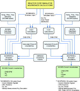
The state parameters, algorithm, and measurement uncertainties are stochastically simulated to generate a state parameter probability density function. The 95/95 probability/confidence level of this function is then root-sum-squared with the other uncertainties to determine the SCOPS or SCOMS overall uncertainty factors. The resultant uncertainties of the two groups are then effectively combined in a deterministic manner. A systematic diagram and uncertainty components for an uncertainty analysis to determine these overall uncertainty factors are presented in and .
Table 4. Uncertainty components used in uncertainty analysis.
SCOPS or SCOMS overall uncertainty factors are calculated by comparing the results between a simulator model and a SCOPS or SCOMS model. The simulator model provides a reference solution with the coupling of neutronics and thermohydraulic code calculation. The MASTER code provides the reference axial power distribution of the hot-pin and Fq and the FAST code calculates DNB-OPM with given axial power shapes and randomly sampled operating variables (i.e. temperature, flow, and pressure) within the SCOPS operating range. The sampled individual variable includes random error. On the other hand, SCOPS synthesizes axial power distribution of the hot-pin with MASTER providing the excore detector signal and control rod position which include random error. In addition, SCOPS calculates Fq and DNB-OPM with synthesized axial shape and sampled operating variables. These independently calculated parameters are compared to each other as expressed in Equation (12). The uncertainty analysis procedure of SCOMS is the same except that an incore detector signal is used instead of an excore detector signal.
5. Preliminary uncertainty analysis
The newly developed statistical combination of the uncertainties method is applied to the calculation of SCOPS and SCOMS overall uncertainty factors. The overall uncertainty analysis established that the adjusted LPD and DNBR are conservative at a 95/95 probability confidence level throughout the core cycle with respect to the actual core conditions. The probability distribution functions associated with the algorithm and sensor uncertainties are analyzed to obtain the LPD and DNBR overall uncertainty factors based on a 95/95 probability/confidence tolerance limit.
5.1. Neutronics and thermohydraulics analysis
The MASTER code generates more than 1000 axial power shapes at each time-in-life. A MASTER data file includes various core parameters representing the core condition, such as the system pressure, temperature, boron concentration, peaking factors, control rod group position, incore and excore detector signals, and core axial power (average and five-hot-pin) distributions. A MASTER data file is used as the basic data in Fq and DNBR calculations. FAST calculates the DNB-OPM per axial shape and provides a data file to be used in the uncertainty analysis of SCOPS and SCOMS.
5.2. Uncertainty factors analysis
The overall uncertainty analysis requires input uncertainties for the input parameters. Individual uncertainties for the SMART initial core are assumed and summarized in and . Individual uncertainties of all variables (pressure, temperature, and flow rate) are randomly sampled within the range and then added to the original value. Since most of the uncertainty values are not available (or suitable) for the SMART core, YGN 3&4 uncertainty data are used [Citation12,13]. However, a 10% additional uncertainty is added to the original YGN 3&4 uncertainty data by engineering judgment. Additional uncertainty may not appropriate value, but it is certain that this approach will induce conservative results. If actual uncertainty data are available for SMART, then supplementary analysis should be performed. Uncertainties of individual variables of and are 110% uncertainties of YGN 3&4 of Refs. [Citation12] and [Citation13]. SAM is a 3×3 shape annealing matrix and used in converting 3-level of axial excore detector signals into 3-level of core peripheral powers. Each element of SAM is a weighting function between the core power and detected power at the excore detector position. SAM is statistically treated with a probability density function file. RSF and BPPCC uncertainties are also considered. These parameters are used in synthesizing the core average axial power distribution with the excore detector signal and control rod position.
Table 5. Individual uncertainties for overall uncertainty factors of SCOPS.
Table 6. Individual uncertainties for overall uncertainty factors of SCOMS.
Uncertainty analysis codes (SCOPSIM and SCOMSIM) were developed to calculate the overall uncertainty factors of SCOPS and SCOMS. These codes are similar to the CPCSIM and COLSIM codes currently used in CE-type PWRs [Citation14,15]. These codes consist of several functional components, i.e. input routines, certain parts of SCOPS and SCOMS related to the power distribution synthesis and DNBR calculation algorithm, statistics routines, and a plotting package. SCOPSIM and SCOMSIM input files require additional uncertainties, Fxy measurement, POL-derivatives, computer processing uncertainties, engineering factor, etc. These uncertainties are combined in a deterministic manner. Fxy is multiplied to the core average axial power distribution to generate the hot-pin power shape and provided with a pre-calculated table and verified during startup testing. A POL-derivative is defined as ∂POL/∂Fr and used in the calculation of uncertainty factor for DNBR calculation
shows the SCOPS overall uncertainty factors. The overall results are similar to those of YGN 3&4 cycle 1. The Fq uncertainty factor (BERR3) increases as burnup continues. The reason is expected to be from the fact that the SAM and BPPCC used in the synthesis of axial power shape are not sufficiently optimized to represent the overall core condition. Also, the values RSF and Fxy provided by a function of burnup are preliminary values. Generally, the values of SAM and BPPCC are calculated throughout the startup test. Incore snapshot data are collected during the ascension from low power to an intermediate power level. In addition, RSF and Fxy are also calculated with measured data during startup test. Therefore, if verified final data are used in SCOPS uncertainty analysis, more improved results are expected. shows the calculated SCOMS overall uncertainty factors, and overall results are similar or more improved compared to those of YGN 3&4 cycle 1. The reason for this is that SCOMS adopts the DPCM3D method in the power distribution synthesis and the FAST algorithm in the DNBR calculation. As mentioned above, SCOMS synthesizes the 3D core power distribution. Thus, more realistic core conditions such as hot-pin power distributions as well as core peaking factors are provided in the uncertainty analysis. In addition, by adopting the FAST algorithm without any change, modeling uncertainty between the simulator and SCOMS is basically ruled out. The overall uncertainty factors shown in and are applied in DNBR and LPD calculation. BERR1 and EPOL2 are used in DNBR calculation and BERR3 and UNCERT are used in LPD calculation as multiplicative or additive terms. That assures, at least with a 95% probability, at a 95% confidence level, that calculated DNBR and LPD are more conservative than those of actual values.
Table 7. SCOPS overall uncertainty factors of the SMART initial core.
Table 8. SCOMS overall uncertainty factors of the SMART initial core.
6. Thermal margin assessment
The thermal margins for SCOPS and SCOMS are estimated based on the available overpower margin (AOPM) and the overall uncertainties (process uncertainty and instrumentation uncertainty). The overpower means the power at which a fuel design limit (i.e. DNB or fuel centerline melting) is reached for a given set of operating conditions. Axial power shapes are at a steady-state 100% power with equilibrium xenon and all control rod withdrawal condition. All other plant conditions are assumed to be in nominal conditions, including the core inlet temperature, system pressure, and flow. The minimum measured core flow rate (105% of the designed flow) was conservatively used to calculate the DNB AOPM.
SCOPS and SCOMS net DNB and LPD overpower margins were calculated following the standard procedure [Citation16]. – show evaluated margins. The minimum DNB and LPD overpower margin were calculated at the BOC condition. The DNB overpower margin is less than the LPD overpower margin owing to the low linear power density of the SMART core and 125.50% of SCOMS DNB-OPM is large enough to accommodate 15% additional thermal margin of SMART. 40% ROPM was used in DNB-OPM calculation and it was evaluated through safety analysis for the SMART core.
Table 9. SCOPS LPD overpower margin of the SMART initial core.
Table 10. SCOPS DNBR overpower margin of the SMART initial core.
Table 11. SCOMS LPD overpower margin of the SMART initial core.
Table 12. SCOMS DNBR overpower margin of the SMART initial core.
7. Conclusions
KAERI has developed a system-integrated modular advanced reactor, SMART, for seawater desalination and electricity generation with a 330 MW thermal power capacity. Standard Design Approval (SDA) for SMART was granted on 4 July 2012 by the Korea Nuclear Safety and Security Commission (NSSC). This marks the first license for an integral-type reactor in the world. Also, SCOPS and SCOMS were developed as an advanced real-time core protection and monitoring system for SMART. In this paper, the design features and characteristics of SMART were described. Also, the overall uncertainties and thermal margin of SCOPS and SCOMS were evaluated.
As described, SCOPS and SCOMS have the following design features and characteristics:
SCOPS simplifies the protection system by directly connecting the four RSPT signals to each core protection channel.
CEAC hardware is no longer used.
SCOMS adopts a 3D power distribution synthesis method, and a power distribution synthesis error is therefore basically ruled out.
SF-1 CHF correlation was newly developed for the SMART fuel assembly.
SCOPS/SCOMS functional modules were optimized by considering the algorithm characteristics and execution time requirements.
A fast-running DNBR calculation code, FAST, was developed, and the DNBR algorithm of FAST was embedded in SCOPS and SCOMS.
The performance of the SCOMS 3D power distribution synthesis method was evaluated, and SCOMS shows negligible power distribution errors and is less sensitive to the number of available detectors. A technically reliable uncertainty analysis method was developed and the overall preliminary uncertainty analysis was evaluated for SCOPS and SCOMS. The overall results are similar or more improved compared to those of YGN 3&4 cycle 1. The overall uncertainty factors of SCOMS are particularly improved as SCOMS adopts the DPCM3D method and FAST algorithm for the power distribution and DNBR calculation. In addition, the thermal margins were estimated based on the available overpower margin. The DNB overpower margin is less than the LPD overpower margin, and SCOMS DNB-OPM is sufficient to accommodate the ROPM and top-tier requirement.
From the above results, SCOPS and SCOMS are judged to be appropriate and well designed for the SMART integral reactor as a digital protection and monitoring system.
Nomenclature
| AOPM | = | Available overpower margin |
| AO | = | Axial offset = |
| BERR0 | = | Thermal power uncertainty bias used in DNBR calculation |
| BERR1 | = | Power adjustment factor used in DNBR calculation |
| BERR2 | = | Neutron flux power bias used in DNBR calculation |
| BERR3 | = | Power adjustment factor used in LPD calculation |
| BERR4 | = | Power bias used in LPD calculation, additive |
| BOC | = | Beginning of cycle |
| BPPCC | = | Boundary power point correlation coefficient |
| CEAC | = | Control element assembly calculator |
| CHF | = | Critical heat flux |
| COLSS | = | Core operating limit supervisory system |
| CPC | = | Core protection calculator |
| CPCS | = | Core protection calculator system |
| CRA | = | Control rod assembly |
| DNB | = | Departure from nucleate boiling |
| DNBR | = | DNB ratio |
| DNB-OPM | = | DNB overpower margin |
| DPCM3D | = | Direct 3D power connection method |
| EOC | = | End of cycle |
| EPOL2 | = | Adjustment factor used in DNB–POL calculation |
| FAST | = | Fast running DNBR calculation code |
| Fq | = | 3D power peaking factor |
| Fr | = | Axially integrated 2D power peaking factor |
| Fxy | = | Planar radial peaking factor |
| ICI | = | Incore instrumentation |
| LCO | = | Limiting conditions for operation |
| LPD | = | Local power density |
| LPD-OPM | = | LPD overpower margin |
| MASTER | = | Multipurpose analyzer for static and transient effects of reactors |
| MOC | = | Middle of cycle |
| POL | = | Power operating limit |
| OP△T | = | Overpower delta temperature |
| OPM | = | Overpower margin |
| OT△T | = | Overtemperature delta temperature |
| ROPM | = | Required overpower margin |
| RSF | = | Rod shadowing factor |
| RSPT | = | Reed-switch position transmitter |
| SAM | = | Shape annealing matrix, Sij, i = 1, 3, j = 1, 3 |
| SCOMS | = | SMART core monitoring system |
| SCOPS | = | SMART core protection system |
| SCU | = | Statistical combination of uncertainties |
| SMART | = | System-integrated modular advanced reactor |
| UNCERT | = | Adjustment factor used in LPD–POL calculation |
| YGN | = | Younggwang nuclear plant |
Acknowledgements
This work was supported by the National Research Foundation of Korea (NRF) grant funded by the Korea government (MEST) (No. 2013M2B9A1024408).
References
- Koo BS, Hwang DH, In WK. SMART core protection system design report. Daejeon (Korea): Korea Atomic Energy Research Institute; 2012.
- Koo BS, Hwang DH, In WK. SMART core monitoring system design report. Daejeon (Korea): Korea Atomic Energy Research Institute; 2012.
- Han KI. OPΔT and OTΔT trip setpoint generation methodology. J Korean Nucl Soc. 1984;16(2):106–115.
- Kim YB. Functional design requirements for a core protection calculator system. Daejeon (Korea): Korea Nuclear Fuel Co. Ltd.; 2004.
- Kim YB. Functional design requirements for a core operating limit supervisory system for Korean standard nuclear power plant. Daejeon (Korea): Korea Nuclear Fuel Co. Ltd.; 2005.
- Koo BS, Lee CC, Kim KK. An on-line core protection system using 4 channel CEA position signals and the method thereof. Korea Patent, Appl . No. 2006-0083504.
- Cho JY, Lee KB, Koo BS. 3D power synthesis methodology for SMART core monitoring system. Daejeon (Korea): Korea Atomic Energy Research Institute; 2007.
- Kwon H, Seo KW, Kim SJ, Hwang DH. Development of fast running DNBR calculation code [CD-ROM]. Paper presented at: Trans Korean Nucl Soc.; 2010 Oct 21–22; Jeju, Korea.
- Hwang DH. Development of SF-1 CHF correlation. Daejeon (Korea): Korea Atomic Energy Research Institute; 2010.
- Cho JY, Zee SQ, Lee CC, Song JS, Joo HG, Park SY, Kim KS, Lee KB, Kim HY, Koo BS. MASTER 3.0 user's manual. Daejeon (Korea): Korea Atomic Energy Research Institute; 2004.
- Cho JY, Song JS, Lee KB, Lee CC. On-line power distribution generation for SMART core [CD-ROM]. Paper presented at: Trans Korean Nucl Soc.; 2007 Oct 25–26; Pyeongchang, Korea.
- Auh GS. YGN 3&4 cycle 1 CPC overall uncertainty analysis. Daejeon (Korea): Korea Atomic Energy Research Institute; 1988.
- In WK. Preliminary COLSS overall uncertainty analysis for YGN 3&4 cycle 1. Daejeon (Korea): Korea Atomic Energy Research Institute; 1988.
- CPCSIM user's manual. Monroeville (PA): Westinghouse Electric Company; 2004.
- COLSIM user's manual. Monroeville (PA): Westinghouse Electric Company; 2004.
- In WK, Hwang DH, Yoo YJ, Zee SQ. Assessment of core protection and monitoring systems for an advanced reactor SMART. Annal Nucl Energy. 2002;29(5):609–621.

