Abstract
Flood barriers are important defenses which will reduce the internal flood-induced failure risk of safety-related equipment in the turbine building. Contrarily, the degradation of flood barriers will increase the risk of internal flood-induced common cause failure (CCF). Two layouts of auxiliary feedwater pumps system are compared to demonstrate the quantitative risk assessment of the possible degradation of flood barriers. The alpha decomposition method has been developed by the authors in order to quantitatively evaluate the CCF parameters based on the causal inference. Occurrence frequency and CCF triggering ability are two important elements which will decide the CCF risk significance of potential common causes. The seismic-induced internal flood combining with the degradation of flood barriers is analyzed. The degradation of flood barriers is treated as a stochastic process and a Markov model is applied to consider the time-dependent states. The failure time of three auxiliary feedwater pumps is calculated based on the water flow rate through flood barriers. CCF triggering abilities of internal floods are calculated which are represented as decomposed alpha factors. This article shows the updating process of CCF parameters according to Bayesian inference and hypothetical databases. It is concluded that the issue of CCF modeling is not only decided by the number of redundant components but also decided by causes and plant-specific design.
1. Introduction
In response to the lessons learned from the Fukushima Daiichi nuclear power station accident, the safety margins evaluation and safety enforcement of the nuclear power plants (NPPs) should be performed immediately [Citation1]. The defense strategies against the common cause failure (CCF) are of great importance, especially against the CCFs which are initiated by external events. Whether defense strategies are successful or not is an important factor to estimate parameters in the procedure of probabilistic risk assessment (PRA). Defense strategies are a set of operational, maintenance and design measures that are taken to diminish the frequency and/or the consequence of CCF events. Physical barriers, monitoring and awareness, and diversity are examples of defense strategies [Citation2]. Therefore, the probability of CCF would be reduced after the application of defense strategies, and on the other side, the probability of CCF would be increased after the degradation of defense strategies.
Research found that there was inadequate design control to ensure that safety-related equipment was protected against damage from the rupture of a pipe or tank resulting in serious internal flooding or excessive steam release [Citation3]. The turbine building is where a lot of water sources are located. The design without flood barriers did not ensure that the auxiliary feedwater (AFW) pumps would be protected from random or seismic-induced internal flood in the turbine building. The internal flood is one potential cause of CCF events, and flood barriers are one defense strategy to protect the AFW pump system from internal flood. Research shows that the seismic-induced secondary events should be considered and the PRA standards for coupled phenomena of earthquake should be established [Citation1]. Therefore, the CCF parameters vary from the systems before the construction of flood barriers to the systems after the construction of flood barriers. Furthermore, the seismic-induced degradation of flood barriers will increase the risk of CCF.
The alpha factor model has been widely applied in the quantitative assessment of CCF risk. The alpha factors are determined by the respective failure events occurred in a targeted system and the amount of redundant components. Because the CCF risk of redundant system with flood barriers is different from that of the system without flood barriers, the alpha factor model based on generic databases is unable to reflect the specific design [Citation4,5]. The alpha decomposition method had been developed by the authors to evaluate the CCF parameters (alpha factors) according to causal inference [Citation6]. By the alpha decomposition method, the update of CCF parameters is conducted through Bayesian inference with Markov chain Monte Carlo (MCMC). Previous work by the authors demonstrates the estimating process of CCF parameters after the application of defense strategies [Citation7,8]. In the current article, the change of CCF parameters after the seismic-induced degradation of flood barriers is analyzed. Since the process of seismic-induced degradation is probably unknown in the real analysis, a Markov model is applied to simulate the transition between states of flood barriers. Two layouts of AFW pump system are compared to emphasize the importance of plant-specific design in the process of CCF parameter estimation. Finally, it is demonstrated how to apply the result of flood analysis to estimate CCF parameters.
2. Two layouts of auxiliary feedwater pumps system with flood barriers
The estimates of CCF risk should reflect issues including failures, causes and system-specific design. Defense strategy will reduce the occurrence probability or mitigate the consequence of CCF events. Flood barriers can prevent flood water from the safeguards alley, where safety-related components are located. When a seismic-induced flood happens, the flood barriers are probable to fail because of the occurrence of seismic shock. Two layouts of flood barriers are considered: parallel flood barriers and sequential flood barriers. For the purpose of easy understanding, an AFW pump system of three redundant pumps is taken into consideration. The authors would like to caution that in the current article, the example of the three-component system, with flood barriers and related hypothetical databases elsewhere, is for illustration only. The purpose of this article is to demonstrate the application of the alpha decomposition method to quantitative CCF risk assessment involving plant-specific design and causal inference, which can be extrapolated to all safety-related redundant systems with multiple components and potential causes.
2.1. Flood sources and flood propagation
Failures of non-safety-related water system will flood the turbine building and subsequently impact the safety-related AFW pump system. According to safety-significance evaluation of Kewaunee Power Station on the subject of internal flood, only the service water (SW), circulating water (CW) and fire protection water (FPW) contain sufficient volume or lines large enough to release fluid to the point that equipment in safeguards alley would be threatened [Citation3]. Therefore, three most hazardous flood water sources are considered in this article: CW, SW and FPW. Hence, the fault tree for the occurrence of internal flood can be obtained in . To simplify the current problem, initiating events of internal flood is assumed as three independent failures of water systems (CW, SW and FPW) and one CCF of all water systems. Pumps without the protection of barriers will fail as a result of severe flood water.
The randomly occurred flood water will be obstructed by intact barriers so that AFW pumps can be protected. According to the seismic classification of structures, systems and components in NPPs, the water systems in the turbine building and flood barriers are non-safety-related but the AFW pumps are safety-related. Thus, it is probable that water system and flood barriers fail dependently for a severe earthquake, so the flood water will propagate through degraded flood barriers to where the AFW pumps are located. Even if the AFW pumps survive a severe earthquake, they might fail as a result of flood propagation in the safeguards alley thereafter.
2.2. Parallel flood barriers (Layout 1)
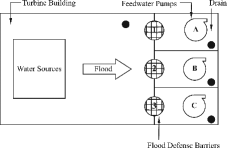
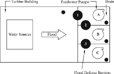
As shown in , all three flood barriers in Layout 1 directly contact the flood water. All successful flood barriers are well sealed at the seam. If flood occurs, seismically flawed barriers will start to degrade, and flood water will leak to safeguards alley. Since all the three flood barriers are identical from the perspective of locations, there are three possible scenarios of failure:
Seismic-induced one-barrier failure;
Seismic-induced two-barrier failure;
Seismic-induced three-barrier failure.
If the flood is severe enough, failed barriers will result in failed pumps. Three scenarios will finally correspond to three different types of CCF events. Under the condition of a severe earthquake, the occurrence frequency fractions of three scenarios are subjectively assumed as 0.2, 0.2 and 0.6, respectively. This set of occurrence probability fraction is taken as an example for demonstration, and the actual failure occurrence probability fraction should be referred to specific plant design.
2.3. Sequential flood barriers (Layout 2)
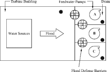
As shown in , all three flood barriers are designed sequentially. Only Barrier 1 directly contacts the flood water. The CCF events are determined by which flood barrier is failed. As introduced earlier, there are three different scenarios.
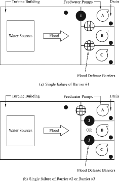
2.3.1. Seismic-induced one-barrier failure
As shown in (a), if Barrier 1 is failed, severe flood water will result in a single failure. The black circle means the failed flood barrier in the figure. Otherwise, as shown in (b), if Barrier 2 or Barrier 3 is failed, severe flood water will not propagate into where AFW pumps are located. No failure occurs under this situation.
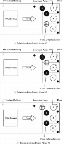
2.3.2. Seismic-induced two-barrier failure
Three possible CCF events are demonstrated in . It is different from Layout 1 that inside barriers are protected by outside barriers. (a) describes the possible situation that Barriers 1 and 2 are failed but Barrier 3 is successful. If the flood water is severe enough, pumps A and B will fail, so a partial CCF event happens. (b) describes the possible situation that Barriers 1 and 3 are failed but Barrier 2 is successful. Only pump A will fail as a result of severe flood water, which means a single failure. (c) describes the possible situation that Barriers 2 and 3 are failed but Barrier 1 is successful, so there is no pump failure even if a severe flood occurs.
2.3.3. Seismic-induced three-barrier failure
When all the three barriers are failed as a result of an earthquake, all redundant pumps will be affected by the flood water. This scenario is shown in .
All the three scenarios represent that Layout 2 will reduce the potential CCF risk caused by the internal flood comparing with Layout 1. Under the condition of severe flood, failed water-contacted barriers will result in failed pumps, so the three scenarios refer to different types of CCF events. Possible failure events for Layouts 1 and 2 are listed in . Similar to the assumption of Layout 1, the occurrence probabilities of three scenarios for Layout 2 are assumed as 0.2, 0.2 and 0.6, respectively. The specific layout of the AFW pump system will affect CCF parameters (alpha factors). In the following contents of the current article, it is demonstrated how to do the quantitative calculation of updated CCF parameters (alpha factors).
Table 1. Possible failure types for two layouts.
3. Markov model for the degradation of flood barriers
The failure process of flood barriers is treated as a stochastic process in this article. Markov model is applied for a quantitative degradation modeling and is used to set up a set of linear coupled differential equations whose solution provides the time-dependent probabilities of occupying states of the model [Citation9,10]. The input evidence to quantify the Markov model includes the occurrence frequency of necessary states with hypothetical experiments.
The schematic diagram of four-state Markov model is described in . The Markov model shows the degradation process of flood barriers under the situation of seismic shock and flood water. After the occurrence of a seismic shock, flood barriers will probably be intact, flawed, deformed or failed. The differences of all initiating states are water leak rates through barriers. Flood water will cause the transition of barrier states downwardly in . For instance, if a barrier is flawed by an initiating shock, the subsequent flood will gradually lead the flaw to more serious states (deformed or failed). The description of four Markov states is shown in , in which critical water flow rates are 0 (for leakage judgment), drainage ability (for deformation judgment) and maximum (for failure judgment). The transition parameters between Markov states are assumed as constant with uncertainty. The investigation of physics-based barrier degradation is not provided in the current article, and it should be confirmed that transition parameters in the actual process are not only time-dependent but also physics- and scenario-dependent. There are four discrete and mutually exclusive states (S, L, D and F) in the current Markov model. The definition of four transition parameters is provided in .
Table 2. Description of four Markov states.
Table 3. Description of four transition parameters.
The Markov model can be described by four ordinary differential equations (ODEs). Initiating states are decided by the severity of seismic shock which will initiate the occurrence of both the internal flood and barrier degradation. The summary of prior distributions and likelihood functions for initiating states and transition parameters is provided in .
Table 4. Uncertainty distribution assumption for Markov parameters.
The initiating states are written as
(1)
The ODEs are given by
(2)
(3)
(4)
(5)
The sum of probabilities of four states remains 1 at the same time t:
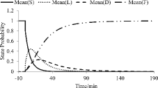
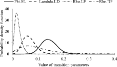
(6) Therefore, with the assumption of all transition parameters and suitable data record, the numerical solution of Markov states and transition parameters can be obtained by Bayesian inference with MCMC. The hypothetical database of Markov state is assumed in . The data of seismic shock is used to update the initiating states and the data of flood propagation is used to estimate the transition parameters. Based on and assumed likelihood functions as well as prior distributions, time-dependent probabilities (mean value) of Makrov states are shown in . The results for transition parameters are shown in in the form of posterior distributions with the demonstration of uncertainties. Transition rates determine how fast the flood barrier can transform from leakage state to final failure.
Table 5. Assumed water flow rate through barriers for Markov states.
4. Water flow rate and water height in each AFW pump room
The flood water flow rate through one barrier is decided by the volume of flood water source and the leakage of the barrier. The leakage of a barrier is determined by its state, which is assumed in . Therefore, the expected water flow rate through a barrier is given by
(7)
Table 6. Calculation assumption for water flow rate through a barrier.
Assumptions of the calculation are listed in . The minimal time to reach the critical water height (CWH) can be calculated by Equation (8), and all the parameters in the equation can be referred in .
(8)
Table 7. Hypothetical experiments with states account for the estimation of transition parameters.
4.1. Water flow rate and water height of Layout 1
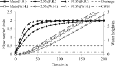
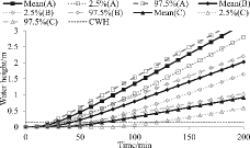
Scenario 3 introduced in Section 2.2 is chosen to show the change of water flow rate with time through barriers. The results of the other two scenarios can be obtained accordingly. shows the estimation of water flow rate and water height in each room. Based on the mean value, it takes 29 min for the water to be accumulated in a room until it reaches the CWH. Compared with the minimal time to reach CWH (without flood barrier), the time is postponed as much as 21 min because the existence flood barrier extends the propagation of flood temporarily, while the barrier degrades as a result of seismic shock and flood hazard. Finally, the leakage rate is larger than the drainage ability and the accumulated water will affect the functional availability of pumps.
4.2. Water flow rate and water height of Layout 2
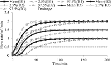
The calculation assumption is the same as Layout 1 which is shown in . The water flow rate through each barrier in Layout 2 is different from Layout 1 except Barrier 1. It is also important to recognize which barrier is failed by possible seismic shocks. Scenario 3 introduced in Section 2.3 is chosen to demonstrate the process of calculation. Other scenarios can be analyzed accordingly. Moreover, it is difficult to distinguish whether the water is accumulated or flows to the next room, so it is conservatively assumed that the possible accumulated rate and flow rate (to next room) are the most credible maximum values.
The water flow rate via Barrier 1 in Layout 2 is the same as that of barriers in Layout 1, which is written as
(9)
The degradation process is physically assumed to be the same as that of Barrier 1. Thus, the maximum water source through Barrier 2 from Room A is given by
(10)
Here, at(Barrier 2) is the maximum value of possible water flow to Barrier 2 at time t; Flow ratet(Barrier 1) is the water flow rate though Barrier 1 at time t; Drainage is defined in . If at time t1 + 1, it means that the water starts to accumulate and the accumulated water will cause Barrier 2 starting to degrade. It is mathematically written as
(11)
Here, bt(Barrier 2) is the water flow rate through Barrier 2 at time t. The water flow rate through Barrier 2 can be given by
(12)
Therefore, the water flow rate through Barrier 3 can be calculated similarly, based on the accumulated water in Room B, which is given by
(13)
Here, ct(Barrier 3) is the maximum value of possible water flow to Barrier 3 at time t; Flowratet(Barrier 2) is the water flow rate through Barrier 2 at time t; dt(Barrier 3) is the water flow rate through Barrier 2 at time t. The water flow rate through each barrier can be calculated and is described in . There is a significant change of flood water leakage rate compared with the result of Layout 1. The flow rates through Barriers 2 and 3 are mitigated. It provides important mitigation time for safety-related measures. Hence, one can calculate the conservative time when water height reaches the CWH and the result refers to . In detail, it is observed that the time for each room reaching the CWH is different from that of Layout 1. The flood environment around each barrier is different from others in Layout 2.
4.3. Common cause failure analysis of Layouts 1 and 2
To continue the analysis conducted in Sections 4.1 and 4.2, Scenario 3 of Layouts 1 and 2 is analyzed to demonstrate the risk of CCF caused by the internal flood. According to the possible water height in each room, the failure state of each pump can be decided. The criteria can be written in a mathematical way:
(14) Here, SC is the acronym of state criteria; Exp(WH) is the expected water height.
4.3.1. Layout 1
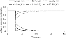
Under Scenario 3, all three flood barriers are flawed by the earthquake, the expected water height in three rooms is treated as identical, which is shown in . It can be judged from that the leak rate at states of Deformation and Failure is larger than the Drainage ability. Therefore, these two states will result in the water accumulated in the room. The probability of complete CCF (3/3) of AFW pumps can be written as
(15) Here, Pt(D) and Pt(F) are probabilities of states Deformation and Failure at time node t; SC is the criterion whether the state of AFW pump is success or failure, which is defined by Equation (14).
The time-dependent probabilities of failures for Layout 1 is shown in . In , the single failure is noted as 1/3 and the complete CCF is noted as 3/3. After the expected water level is higher than the CWH, the complete CCF risk will start to increase significantly. The expected water height can be referred in . Moreover, it reaches the stable value of 1 in a short term. Under this situation, because there is no risk of partial CCF event involving two components, the risk of partial CCF is always 0.
4.3.2. Layout 2
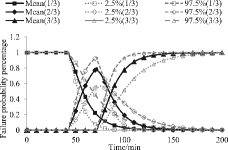
Under Scenario 3, all three barriers are flawed by the earthquake, and then degrade as a result of accumulated water in the adjacent room. The probability of partial CCF (2/3) and complete CCF (3/3) of AFW pumps can be written as
(16)
(17) Here, Pt(D)i and Pt(F)i are probabilities of states Deformation and Failure for Barrier i at time node t; SCj is the criteria for the failure involving j components.
The time-dependent probabilities of failures for Layout 2 are shown in . Compared with , the occurrence of CCF event involving three components is significantly postponed.
4.4. Estimation of flood hazard under different scenarios
There are three flood sources considered in Section 2.1. The fault tree of the occurrence of internal flood is described in . The independent and CCF probabilities of water systems are referred in . The hypothetical failure probabilities are assumed based on [Citation3]. To be cautioned, the flood occurrence frequency should be a plant-specific issue, and the data here is for explanation only.
Table 8. Hypothetical flow rate of flood water sources.
Different layouts of flood barriers mean different flood risks. Based on the quantitative evaluation of flood propagation within two layouts and the data assumed in and , the probability of each failure type can be calculated as shown in . Compared with the results of Layout 1, under the situation of same flood scenario, CCF risk of Layout 2 has been degraded to failures involving less components, and probabilities of partial and complete CCF are reduced. Layout 2 shows advantage over Layout 1 since the successful barrier in Layout 2 tends to protect more components.
Table 9. Failure probability distributions for different scenarios.
5. The estimation of decomposed alpha factors and global alpha factors
The alpha factor model is widely used in the quantitative modeling of CCF. The specific explanation of the alpha factor model can be obtained from [Citation2,Citation11]. The alpha decomposition method has been developed by the authors. Alpha factors in the alpha factor model are denoted as global alpha factors, and alpha factors for each cause are denoted as decomposed alpha factors. In this section, it is demonstrated how to apply the CCF risk analysis in Section 4 to update the estimates of alpha factors in PRA analysis.
5.1. Review of the alpha decomposition method for CCF analysis
Previously published articles have proved that global alpha factors are decomposable based on causal inference [Citation6–8]. For the simplest consideration, a redundant system is considered, which is composed of three components (A, B and C) and affected by three potential common causes (Cause 1, Cause 2 and Cause 3); the regression correlation between global alpha factors and decomposed alpha factors can be given by
(18) Here, αj represents the CCF risk involving j components; αCij represents the CCF risk of Cause i involving j components; ri represents the fraction of occurrence frequency of Cause i. In this article, Cause 1 (C1) can be considered as flood. When defense barriers against flood are applied to redundant systems, the CCF risk of flood will be changed, so it is meaningful to reflect this change in the parameter estimation of global alpha factors [Citation7]. Inversely, when the defense barriers of two layouts are degraded as a result of external events (e.g. earthquake), distributions for global factors should reflect two types of degradation accordingly.
With the operational record of CCF events and cause information, the global alpha factors and decomposed alpha factors can be calculated via Bayesian inference with MCMC. MCMC approaches to sampling directly from the joint posterior distribution of aleatory model parameters have led to tremendous advances in Bayesian inference capability in a wide variety of fields, especially in nuclear PRA [Citation12,13]. Intractable problems of integrations (prior distributions and likelihood functions) have been solved with powerful software packages. Subjective prior distributions (global alpha factors assumed as Dirichlet distributions) and limited operational database (occurrence record of failures and causes) make the estimation of important parameters (posterior distributions for alpha factors) more reasonable. The calculation of previously introduced Markov model and the alpha decomposition method is conducted by OpenBUGS version 3.2.2.
5.2. Calculation of decomposed alpha factors and global alpha factors
The decomposed alpha factors of internal flood represent how serious consequence the internal flood will result in. Based on the result of possible CCF events in , the decomposed alpha factors can be calculated by the following equation:
(19) Here, αC1j represents the CCF risk caused by the internal flood and
is the probability of j components failed.
The calculated decomposed alpha factors for both layouts are shown in . It is possible that no failure of pumps occurs when all barriers in Layout 1 and Barrier 1 in Layout 2 are intact, or when the total water volume is not enough to fail the pump functionally (FPW assumed in ). As shown in (rows 2 and 6), the possibility of no failure is screened out during the calculation of alpha factors. It can be observed from that the ratio of complete CCF is reduced for Layout 2 compared with that of Layout 1. The estimates of decomposed alpha factors can be used to update the global alpha factors. Moreover, the updated alpha factors will reflect the specific design, for instance, the difference between Layouts 1 and 2.
Table 10. The estimated decomposed alpha factors for internal flood.
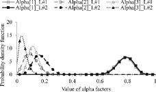
Based on the estimates of decomposed alpha factors of internal flood and the alpha decomposition method (Equation (18)), the update of global alpha factors is demonstrated in . The necessary databases can be referred in previous papers. Gray curves with lined markers represent the CCF risk of Layout 1 and black curves with solid markers represent the CCF risk of Layout 2. The global alpha factors of the AFW pump system of Layout 2 is of less complete CCF than the system of Layout 1. It is useful since the third AFW pump is turbine-driven pump; moreover, the availability of the turbine-driven AFW pump will determine the availability of the AFW pump system. This application shows that the alpha factors are affected by the CCF risk of causes. If more causal information can be used in the evaluation of CCF risk, the results will represent the system-specific design and the innate risk of common causes.
6. Conclusion
Alpha factors in CCF modeling are lumped parameters which are calculated by generic databases. The estimates of alpha factors cannot reflect issues like common causes and specific system design. The alpha decomposition method can be applied to predict CCF parameters. Based on the casual inference and the alpha decomposition method, the updated global alpha factors can reflect the applied defense strategy and specific design.
An AFW pump system with three redundant components is taken as the simplest example to demonstrate how to apply the alpha decomposition method to CCF parameter estimation. Redundant systems with more complicated causal network and components can be analyzed according to the same but more complicated procedure. Following conclusions have been obtained from the current article and supporting references:
The flood barriers are the recommended defense strategies against internal flood. The introduction and degradation of flood barriers will affect the CCF risk. Two layouts of AFW pump system are compared from the perspective of seismic-induced flood risk. The current article quantitatively has analyzed the change of CCF risk according to the introduced flood barriers and difference system design. The introduction of flood barriers will postpone the failure time of AFW pumps. Layout 2 (sequential flood barriers) will reduce the complete CCF risk.
A Markov model has been introduced to model the stochastic failure process of flood barriers. The seismic hazard and failure propagation are quantitatively calculated by Bayesian inference through MCMC method. Time-dependent failure rate and water flow rate through barriers have been calculated, which are pivotal parameters to decide the failure time and states of AFW pumps.
Three failure scenarios of three flood barriers are assumed. The probability distribution of single failure, partial CCF and complete CCF are obtained according to the assumption of the most credible flood scenarios and quantitative flood evaluation. Therefore, the decomposed alpha factors of internal flood are well established. The decomposed alpha factors are used to update the distributions of global alpha factors, which represent the CCF risk of AFW pump system.
Acknowledgements
The authors gratefully acknowledge Professors Takao Nakamura and Eiji Hoashi at Osaka University for discussions and comments. We also wish to thank the anonymous referees for precious comments in preparing the manuscript.
References
- Yamaguchi A, Kirimoto Y, Ebisawa K. Tsunami PRA standard development by Atomic Energy Society Japan (AESJ) (4) unresolved issues and future works. Proceedings of the International Conference on PSAM & ESREL 2012; 2012 June 25–29; Helsinki. Accompanied by: CD-ROM.
- Mosleh A, Rasmuson DM, Marshall F. Guidelines on modeling common-cause failures in probabilistic risk assessment. NUREG/CR-5485. Washington (DC): U.S. Nuclear Regulatory Commission; 1998.
- Dominion Resources Inc. Safety significance evaluation of Kewaunee power station turbine building internal floods, Vols 1 & 2, Revision 1. Innsbrook (VA): Dominion Resources Inc.; 2005.
- Mosleh A, Parry G, Zikria A. An approach to the analysis of common cause failure data for plant-specific application. Nucl Eng Des. 1994;150:25–47.
- Kelly D, Song H, DeMoss G, Coyne K, Marksberry D. Common-cause failure treatment in event assessment: basis for a proposed new model. Proceedings of the International Conference on Probabilistic Safety Assessment and Management (PSAM 10); 2010 June 7–11; Seattle, WA. Accompanied by: CD-ROM.
- Zheng X, Yamaguchi A, Takata T. α-Decomposition for estimating parameters in common cause failure modeling based on causal inference. Reliability Eng Syst Saf. 2013;116:20–27.
- Zheng X, Yamaguchi A, Takata T. Probabilistic common cause failure modeling for auxiliary feedwater system after the introduction of flood barriers. J Nucl Sci Technol. 2013;50:828–836.
- Zheng X, Yamaguchi A, Takata T. Quantitative risk assessment of common cause failure involving the degradation of defense barrier against seismic induced internal flood. Proceedings of Japan-Korea Symposium on Nuclear Thermal Hydraulics and Safety (NTHAS8); 2012 Dec 9–12, Beppu. Accompanied by: CD-ROM.
- Fleming K. Markov model for evaluating risk-informed in-service inspection strategies for nuclear power plant piping systems. Reliability Eng Syst Saf. 2004;83:27–45.
- Fleming K, Unwin S, Kelly D, Lowry P, Toloczko M, Layton R, Youngblood R, Collins D, Huzurbazar A, Williams B, Heasler P. Treatment of passive component reliability in risk-informed safety margin characterization. FY2010 Report. INL/EXT-10-20013. Idaho Falls (ID): Idaho National Laboratory; 2010.
- Rasmuson DM, Kelly D. Common-cause failure analysis in event assessment. Proc Inst Mech Eng. 2008;222:521–532.
- Kelly D, Curtis S. Bayesian inference for probabilistic risk assessment: a practitioner's guidebook. New York (NY): Springer; 2011.
- Kelly D, Curtis S. Bayesian inference in probabilistic risk assessment – the current state of the art. Reliability Eng Syst Saf. 2009;94:628–643.


