Abstract
A simplified fuel handling system design for the demonstration Japan sodium-cooled fast reactor (JSFR) has been proposed. Fast Reactor Cycle Technology Development project phase I results of key technology evaluations on a pantograph fuel handling machine (FHM), a fuel transfer pot with two core component positions, dry spent fuel cleaning and minor actinide-bearing fresh fuel shipping cask are summarized. A full-scale FHM mockup has been fabricated and tested in the air accumulating performance and seismic tolerance data. A mockup fuel transfer pot with fins and chromium carbide coating has been fabricated and tested with sodium accumulating heat transfer performance data. Several sodium cleaning tests using a dummy subassembly has been conducted accumulating cleaning performance data. For fresh fuel shipping cask, a design tool for evaluation of heat transfer capability has been developed and a helium gas cask shows cooling capability of minor actinide-bearing fresh fuel. Those experimental and analytical efforts have shown that key technologies to develop simplified fuel handling system are matured enough to proceed large-scale sodium experiments and conceptual design study for the demonstration JSFR.
1. Introduction
In 1999, the Feasibility Study on Commercialized Fast Reactor Cycle Systems (FS) had been initiated [Citation1]. Surveying various fast reactor concepts like sodium-cooled reactor, gas-cooled reactor, heavy metal-cooled reactor and water-cooled reactor with various fuel like oxide, nitride and metal, the FS concluded to select a mixed oxide fuel sodium-cooled reactor named Japan sodium-cooled fast reactor (JSFR) as a reference concept [Citation2]. Succeeding the FS, the Fast Reactor Cycle Technology Development (FaCT) project is pursuing commercialization of fast reactor cycle system by 2050 under cooperation of MEXT (Ministry of Education, Culture, Sports, Science and Technology), METI (Ministry of Economy, Trade and Industry), utilities, venders and JAEA (Japan Atomic Energy Agency). As results of the FaCT phase I, the key technologies for commercialized JSFR with 1500 MW electric output have been evaluated [Citation3]. The 10 technologies high burn-up core, safety enhancement, compact reactor vessel, two-loop cooling system using high chromium steel, integrated intermediate heat exchanger/pump component, reliable steam generator, natural circulation decay heat removal system, simplified fuel handling system (FHS), containment vessel made of steel plate reinforced concrete, and advanced seismic isolation system have been confirmed to be ready for the phase II development, in which conceptual design of demonstration JSFR with 750 MW electric output and large-scale demonstration experiments are involved.
As for the FHS, the JSFR adopts a simplified FHS with ex-vessel storage tank (EVST) instead of evolutional systems without an EVST based on an FHS survey study [Citation4]. The result of the survey study has indicated that the construction cost of the evolutional systems without EVST do not reduce the construction cost dramatically, which is mainly due to additional safety measures required higher decay heat handling in gas atmosphere and separated fresh and failed fuel storage. From an economical point of view, a longer plant outage of the evolutional systems offsets its advantage of the lower construction cost. On the basis of the results of this comparative study, JSFR has selected the FHS with an EVST. In the FaCT phase I, research and development (R&D) has been conducted to evaluate feasibility of the simplified FHS. This paper provides description of the preliminary conceptual design of the demonstration JSFR FHS and evaluation results on key technologies in the simplified FHS.
2. System design
The preconceptual design of the FHS has been conducted based on the 750 MW demonstration JSFR [Citation5,6]. The design conditions are shown in . The JSFR core is installing minor actinide (MA) and low decontamination fuel considering reduction of environmental burden [Citation7]. For the demonstration JSFR, fuel will be reprocessed from light water reactor (LWR) spent fuel. Various LWR-to-FBR (fast breeder reactor) transition fuels have been investigated, considering various LWR, burn-up, and cooling conditions [Citation8–10]. The FHS design conditions have been identified to cover the wide range of LWR-to-FBR transition fuels. Dimensions of the fuel subassembly (SA) for the demonstration of JSFR are the same of the commercialized JSFR. The batch number of 6 is slightly different from that of FBR multirecycle equilibrium core of 4. Operation cycle is 18 months that is shorter than 26 months of the FBR multirecycle equilibrium core. The maximum decay heat of spent fuel SA after 17 days from reactor shutdown, which means decay heat during refueling is evaluated to be 35 kW with design margin. The spent fuel storage in EVST during one operation cycle and the reduced decay heat is less than 10 kW to handle in the gaseous area. Since JSFR handle MA-bearing fuel, fresh fuel SA also has certain decay heat while conventional fresh fuel does not. In the FaCT design conditions with MA content up to 5% in the homogeneous core, the maximum decay heat of the JSFR fresh fuel is 2.6 kW.
Table 1. Design conditions for JSFR FHS.
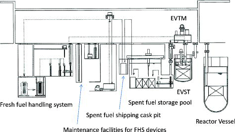
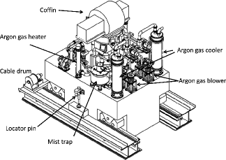
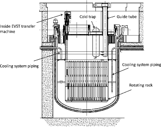
JSFR has adopted a simple FHS with advanced technologies as shown . The JSFR in-vessel FHS consists of a combination of an upper inner structure with a slit (slit UIS) and a flexible arm type pantograph fuel handling machine (FHM) to dramatically reduce the reactor vessel diameter. The FHM is removed during power operation from the reactor vessel. From the reactor vessel to the EVST, a spent SA which is accommodated by a sodium pot is transported by an ex-vessel transfer machine (EVTM) as shown in . A two-position sodium pot has been installed for transportation of SAs from the reactor vessel to the EVST to reduce the refueling time and thereby increase plant availability. Active cooling is not necessary during the transportation from the reactor vessel to the EVST since the sodium pot provides enough heat capacity. Only when the transportation has malfunction and stuck, the sodium pot cooling system that consists with combination of direct and indirect cooling is activated. The EVST has enough capacity for full core evacuation to enhance the plant's in-service inspection and repair capability as shown in . It has 431 SA positions including 84 positions for one refueling campaign, 340 for whole core evacuation and 7 for failed fuel. The diameter of the EVST is 10.5 m with heat removal capacity 9.8 MW. After approximately one-cycle operation, spent fuel SAs are transported to the spent fuel storage pool by EVTM with argon gas cooling. During the transportation to the storage pool, the spent fuel SA is cleaned to remove residual sodium from SA surfaces. The spent fuel cleaning method has changed from the conventional water rinse to argon gas dry cleaning to eliminate a facility for SA cleaning and reduce radioactive liquid waste. After argon gas dry cleaning at the SA guide tube of the EVST, the SA is transported by EVTM and residual sodium is made to be inert using moist argon gas, at the SA lifter at the entrance of the spent fuel storage pool. The storage capacity of the water pool is 227 to maintain the total SA storage capacity of the nuclear building of 658 including storage capacity for 8-year operation, one batch of control rods, a whole core evacuation and failed fuel. A fresh FHS has been designed to accommodate decay heat and radiation from the MA-bearing fuel in accordance with JSFR's core concept, transmuting MAs from LWR and containing trans-uranium elements inside the fast reactor fuel cycle system.
Key technologies for the proposed FHS are listed in . There are four new technologies to be evaluated: flexible arm type pantograph FHM, sodium pot with two core component positions, dry cleaning of spent fuel SA, and fresh fuel shipping cask. JSFR installs the flexible arm type pantograph FHM instead of an offset arm type pantograph FHM in Monju. In the new FHM, positioning of the flexible arm and interaction between the FHM-slit UIS in the seismic conditions are major issues. For the sodium pot for two core components positions, cooling capability for two spent fuel SAs and various conditions is selected as a key issue. For the dry cleaning of spent fuel SA, performance of dry cleaning process, sodium inert process after dry cleaning, and cladding integrity in the spent fuel pool are major issues, since cleaning process is completely different from the conventional wet process with water rinse and the cladding material is changed to the oxide dispersion strengthened (ODS) steel. For the fresh fuel shipping cask, cleaning performance of the shipping cask is selected as a key issue. Since JSFR adopt MA-bearing fuel, cooling and shielding of the fresh fuel cask has to be confirmed, while conventional fresh fuel does not have to take care those points. In the following sections, evaluation results of those key points are summarized.
Table 2. Key technologies in FHS.
3. Flexible arm type pantograph FHM
A full-scale mockup of the pantograph FHM has been manufactured to evaluate basic feasibility [Citation11]. Major requirements on the FHM are as follows:
Slim structure suitable for UIS slit (400 mm width),
Prevention of interact with the UIS,
Positioning accuracy within a few millimeter order,
Stiffness against SA insertion/extraction (25 kN),
Short refueling time (30 min per SA),
Recovery from abnormal events, and
Ease of maintenance and repairing.
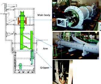
A sketch of the FHM mockup and photographs is shown in . The experiment was conducted in the air with a dummy SA. The gripper mechanism is installed a self-positioning adjustment mechanism which can cover 30-mm offset. However, considering offsets caused by rotating plug motion, FHM rotation, SA deformation due to irradiation/thermal expansion, UIS displacement and offset of UIS/FHM positions, the horizontal positioning accuracy for the mockup FHM in the air is required to be within 3 mm. For the vertical direction, the limit positioning accuracy is set to avoid interaction of the FHM and the SA. Since the gap between the SA top and UIS bottom is 35 mm, the vertical positioning accuracy requirement is evaluated to be 10 mm taking into account FHM/SA offsets and SA swelling. The mockup test showed that the FHM can meet positioning accuracy requirements keeping required speed of 2.3 m/min.
For prevention of interaction between the FHM and UIS, seismic analysis has been carried out using Femap with NX Nastran Ver.9.3.1. Limit of seismic displacement of the FHM is evaluated to be 20 mm in the horizontal direction taking into account UIS displacement, offsets and thermal expansion. And the vertical limit displacement is evaluated to be 15 mm preventing interaction between SA and FHM. The seismic analysis result with solid hexagonal meshes on the design base seismic condition shows that the maximum displacement of 19.6 mm and 5 mm in horizontal and vertical direction, respectively, meeting the requirements. shows stress distribution. The maximum stress is evaluated to be 131 MPa that is lower than the design limit of 304SS yield stress at 200°C of 144 MPa.
Figure 5. Stress with design base seismic conditions [Citation11].
![Figure 5. Stress with design base seismic conditions [Citation11].](/cms/asset/ac8eef98-f9bc-4615-9b8a-04d72eb36709/tnst_a_873360_f0005_oc.jpg)
For recovery from the abnormal events such as FHM arm stuck, comprehensive survey on initiating malfunction has been conducted and proper recovery measures have been listed. The most severe event is gripper malfunction holding SA, since the FHM have to delatch SA before extraction. In those cases, a device to delatch the SA forcedly from the FHM gripper will be inserted from the top of the reactor vessel plug [Citation12].
4. Sodium pot with two core component positions
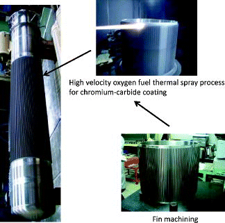
During refueling spent fuel SAs accommodated in the sodium pot are transported from the reactor vessel to the EVST. The JSFR sodium pot has two core component positions to reduce refueling time. In the normal refueling operation, active cooling is not necessary, since the sodium pot has enough heat capacity. When the sodium pot stuck at the reactor vessel guide tube, active cooling system is activated. The cooling capacity of the sodium pot for the demonstration JSFR is 35 kW. To evaluate cooling performance of the sodium pot, a mockup was fabricated and cooling performance was tested [Citation13]. The fabricated mockup pot is shown in . As a result of the fabrication tests, fin machining had no technical issues, and the high velocity oxygen fuel thermal process was selected because it was found to be more suitable for coating on the rather complicated shaped surface such as fin than the detonation process. Properties of the chromium carbide coating such as hardness, thermal conductivity, and thermal expansion coefficient were obtained.
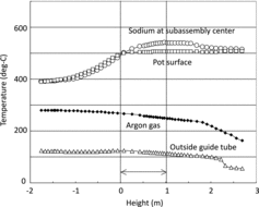
Heat transfer performance tests using the mockup transfer pot have been carried out. The experimental apparatus, simulating the most severe condition of stoppage of the transfer pot in the guide tube on the way from the reactor vessel, is composed of the test pot and guide tube, whose cross section including fin configurations is full-scale to confirm the effect of fin and coating performance in actual condition. The experimental results of emission cooling performance are shown in [Citation13]. Those experimental results are categorized into three groups from the viewpoint of surface conditions of the pot and guide tube as follows:
Figure 7. Experimental results of emission cooling [Citation13].
![Figure 7. Experimental results of emission cooling [Citation13].](/cms/asset/d4a2528c-2d0a-44ad-8ed9-f75df393d91b/tnst_a_873360_f0007_oc.jpg)
Case 1: Dry pot and dry guide tube
Case 2: Sodium immersed pot and dry guide tube
Case 3: Sodium immersed pot and guide tube (hypothetical)
For Case 1, the emissivities of the pot and guide tube are evaluated to be 0.5 and 0.5, respectively. Case 2 shows results after sodium immersion. In Case 2, the cooling performance is as well as Case 1, since sodium on the pot surface is evaporated at first. As the thermal output of the pot grows, the emission from the pot is observed to reduce due to deposition on the guide tube surface. The evaluated emissivities of the pot and guide tube are 0.5 and 0.3 in this case. The Case 3 is a hypothetical case with sodium on the guide tube, since the guide tube in the reactor vessel does not have change to contact with sodium directly. The emissivity of the guide tube is evaluated to be 0.1 in Case 1. At this stage, the sodium pot cooling system has been designed with the conservative emissivity of the hypothetical Case 3.
A three-dimensional (3D) analysis model using CFX code for heat transfer evaluation of the JSFR fuel transfer pot was developed [Citation14]. The heat transfer model inside the pot has been validated using the CCTL-CFR experiments [Citation15]. The heat transfer model outside the pot has been validated using the mockup pot experimental results. Using the developed 3D model, cooling performance of the pot has been evaluated. The calculation results show that the fuel transfer pot can be cooled by combination of indirect cooling with air and direct cooling with argon gas even with the conservative emissivity. One of calculation cases with two SAs with 22.4 kW each is shown in [Citation14]. For a simpler design tool, a two-dimensional (2D) analysis model using ZEPYRUS code was also developed and validated by the 3D analysis model [Citation14]. The sodium pot for the demonstration JSFR has been evaluated. In the calculation, the air flow rate at 60°C for the indirect cooling is 20 m3/min-normal and the argon gas flow rate at 150°C for the direct cooling is 8 m3/min-normal. The results show that the sodium temperature at the center of the SAs is lower than the limit 600°C as shown in .
Figure 8. 3D evaluation on direct-indirect combination cooling [Citation14].
![Figure 8. 3D evaluation on direct-indirect combination cooling [Citation14].](/cms/asset/b1bf95f7-046e-47e8-aa8c-8530eb8d808a/tnst_a_873360_f0008_oc.jpg)
5. Dry cleaning of spent fuel SA
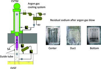
In JSFR, an advanced spent fuel cleaning process is adopted and a spent fuel SA is stored in the water pool directly without canning. A concept of the advanced spent fuel cleaning, so-called dry cleaning is shown in . In the dry cleaning method, a special facility for spent fuel cleaning like the fuel cleaning facility in Monju is unnecessary. The spent fuel discharged from the EVST is hold at the EVST guide tube (a tube through which the EVTM accesses to the EVST) and argon gas circulation by the argon gas cooling system is provided during a certain period to blow away sodium on the spent fuel SA. After the gas blow, the SA is transported to the water pool guide tube by the EVTM. And at the guide tube, residual sodium on the spent fuel SA is inert by moisture argon gas and immersed into the water pool. Since JSFR spent fuel SAs are stored in the water pool without canning, a certain amount of residual sodium is acceptable as long as the water pool purification system can handle it. Water conditions of the JSFR water pool is managed by the purification system and sodium carried into the water pool would be accumulated at the purification system. One major feature of the new cleaning method is that radioactive liquid waste due to spent fuel cleaning is reduced because the new
process is free from spent fuel rinse which cannot avoid a certain amount of liquid waste.
Since the JSFR SA has an inner duct to enhance molten fuel release in case of severe accidents, sodium drain from the inner duct is an issue. In the previous study, inner duct drain tests using inner duct mockups were conducted and drain performance of the inner duct was confirmed. To demonstrate the proposed dry cleaning process, a full-scale mockup of a JSFR fuel SA which involves fuel pin bundle, wrapper tube and inner duct was manufactured and dry cleaning performance tests after sodium immersion were conducted as shown in . The experimental results showed that the residual sodium on the mockup SA is less than 200 g after the cleaning process. Based on the experimental results of residual sodium density of each part of the mockup SA, amount of residual sodium on the JSFR SA was evaluated as shown in taken into account uncertainty and design margin [Citation16]. The residual sodium of the SA is evaluated to be approximately 400 g. After dry cleaning, the spent fuel SA is transported to the water pool guide tube and the residual sodium is made inert by humid argon gas and steam. Experiences in Joyo and Monju showed that duration of the sodium inert process would depend on sodium density on spent fuel SAs and the inert process duration would be approximately 25 min. For the JSFR fuel-handling design, the inert process duration is designed to be 30 min conservatively based on the Joyo and Monju experiences [Citation16]. From the viewpoint of the FHS operation, two SAs in the EVST are transported to the spent fuel storage pool. The pool water can be maintained less than pH 10 with a proper pool purification system and the ODS cladding is thought to be tolerable based on the corrosion experiments [Citation17].
Table 3. Evaluation of residual sodium on cleaned subassembly.
6. Fresh fuel shipping cask
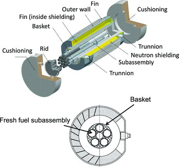
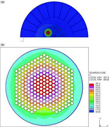
Fresh fuel shipping is always an issue when a sodium-cooled reactor is going to handle MA-bearing fuel that requires shielding and cooling. In the JSFR design range, the fresh fuel SA might have 2.6 kW decay heat per SA. The cladding temperature limits are set to be 395°C for inert gas environment (core inlet temperature) and 300°C in the air [Citation18] to prevent creep damage and oxidation. The JSFR fresh fuel shipping cask adopts helium gas coolant to avoid water contact before core loading and to provide better heat removal performance than other gaseous coolant. A helium gas cask with five-SA positions has been designed as shown in . Two design evaluation models have been developed [Citation19]. Cooling performance is roughly evaluated by the ABAQUS code with a 3D whole cask model. The conservativeness of the whole cask calculation was confirmed by the fact that the cladding temperature evaluated by the detailed SA calculation by Star-CD showing the detail SA calculation, provided lower cladding temperature than that of the whole cask analysis. shows calculation results of a cask with two SAs of 2.6 kW decay heat each. In the 3D whole cask model, the maximum cladding temperature is evaluated to be 367°C, while the maximum temperature from the detail 2D calculation is 351°C. Those analyses show the 3D whole cask model can provide conservative evaluation on the maximum cladding temperature. Relation between accommodated SAs and maximum decay heat has been evaluated as shown . The results show that the proposed helium gas cask can handle SAs with decay heat up to 2.2 kW/SA. Even with higher decay heat SAs, the cask can manage them by reducing SA accommodations from five to a few. It means that all MA-bearing fresh fuel in the FaCT deign range can be handled the proposed helium gas cask.
Figure 13. Cooling performance of fresh fuel shipping cask [Citation19].
![Figure 13. Cooling performance of fresh fuel shipping cask [Citation19].](/cms/asset/3a517dff-cc5a-4caa-b47e-df23c57bcd57/tnst_a_873360_f0013_oc.jpg)
7. Conclusions
A simplified FHS for the demonstration JSFR has been proposed. The FaCT phase I study concluded that the JSFR FHS is feasible. R&D on the flexible arm-type pantograph FHM, sodium pot, and fresh fuel cask shows the feasibility of each technology. A full-scale FHM mockup has been fabricated and tested in the air, accumulating performance and seismic tolerance data. The results from the mockup experiment and analysis have shown that the positioning accuracy of the flexible arm and the seismic tolerance meet requirements. A mockup fuel transfer pot with fins and chromium carbide coating has been fabricated and tested with sodium accumulating heat transfer performance data. Based on the experimental results, design evaluation tools have been developed and validated. And the cooling performance of the sodium pot with two core components positions has been confirmed. Several sodium cleaning tests using a dummy SA has been conducted accumulating cleaning performance data. Based on the experiments, performance of the cleaning process has been confirmed taking into account uncertainty. For corrosion in the spent fuel pool, integrity of ODS cladding has been confirmed based on material experiments. For fresh fuel shipping cask, a design tool for evaluation of heat transfer capability has been developed and a helium gas cask shows cooling capability of MA-bearing fresh fuel. Those experimental and analytical efforts have shown that key technologies to develop simplified FHS are matured enough to proceed large-scale sodium experiments and conceptual design study for the demonstration JSFR.
List of acronyms
| EVST | = | ex-vessel storage tank |
| EVTM | = | ex-vessel transfer machine |
| FBR | = | fast breeder reactor |
| FHM | = | fuel handling machine |
| FHS | = | fuel handling system |
| JSFR | = | Japan sodium-cooled fast reactor |
| LWR | = | light water reactor |
| MA | = | minor actinide |
| ODS | = | oxide dispersion strengthened |
| SA | = | subassembly |
| UIS | = | upper inner structure |
Acknowledgements
This paper includes results of “Technical development program on a commercialized FBR plant” entrusted to JAEA by the Ministry of Economy, Trade and Industry of Japan (METI). And the present study includes the results of “Development of Fuel Handling System” entrusted to The Japan Atomic Power Company (JAPC) by the Ministry of Education, Culture, Sports, Science and Technology of Japan (MEXT).
References
- Aizawa K. R&D for fast reactor fuel cycle technologies in JNC. Paper presented at: Proceedings of GLOBAL 2001; 2001 Sep; No. 050, Paris, France.
- Kotake S, Sakamoto Y, Ando M, Tanaka T. Feasibility study on commercialized fast reactor cycle systems current status of the FR system design. Paper presented at: Proceedings of GLOBAL 2005; 2005 Oct; Tsukuba, Japan.
- Chikazawa Y, Aoto K, Hayafune H, Kotake S, Ohno Y, Ito T, Toda M. Evaluation of JSFR key technologies. Nucl Technol. 2012;179-3:360–373.
- Chikazawa Y, Uzawa M, Usui S, Tozawa K, Kotake S. 2010. Comparison of sodium-cooled reactor fuel handling system with and without an Ex-vessel storage tank. Nucl Technol. 2012;177-3:293–302.
- Usui S, Mihara T, Obata H, Kotake S. Development of advanced loop-type fast reactor in Japan (4): an advanced design of the fuel handling system for the enhanced economic competitiveness. Paper presented at: Proceedings of ICAPP 2008; 2008 Jun; Anaheim, CA.
- Sakai S, Kotake S, Aoto K, Ito T, Kamishima Y, Ohshima J. Conceptual design study toward the demonstration reactor of JSFR. Paper presented at: Proceedings of ICAPP’2010; 2010 Jun; San Diego, CA.
- Mizuno T, Ichimiya M, Kotake S. Advanced oxide fuel core design study for SFR in the feasibility study in Japan. Paper presented at: Proceedings of GLOBAL 2005; 2005 Oct; Tsukuba, Japan.
- Maruyama S, Ohki S, Mizuno T. TRU composition changes and their influence on FBR core characteristics in the LWR-to-FBR transition period. Paper presented at: Proceedings of ICAPP ‘09; 2009 May; Tokyo, Japan.
- Maruyama S, Kawashima K, Ohki S, Mizuno T, Okubo T. Study on FBR core concepts for the LWR-to-FBR transition period. Paper presented at: Proceedings of Global 2009; 2009 Sept; Paris, France.
- Kawashima K, Maruyama S, Ohki S, Mizuno T. Fast reactor core design studies to cope with TRU fuel composition changes in the LWR-to-FBR transition period. Paper presented at: Proceedings of ICAPP ‘09; 2009 May; Tokyo, Japan.
- Katoh A, Chikazawa Y, Obara H, Kotake S. Development of advanced fuel handling machine for JSFR. J Nucl Sci Technol. 2010;47–7:642.
- Katoh A, Hirata S, Chikazawa Y, Uto N, Obata H, Kotake S, Uzawa M. Development of the JSFR fuel handling system and mockup experiments of fuel handling machine in abnormal conditions. Paper presented at: Proceedings of ICAPP2010; 2010 Jun; San Diego, CA.
- Chikazawa Y, Katoh A, Hirata S, Obata H. Heat transfer experiments on fuel subassembly transfer pot for JSFR. J Nucl Sci Technol ( to be submitted).
- Chikazawa Y, Hirata S, Obata H. Development of design evaluation tools for the JSFR Fuel transfer Pot. Nucl Eng Des ( to be submitted).
- Toda S, Ieda Y, Kamide H, Komatsuzaki K. Study of heating/cooling effects on transverse temperature distribution in a FBR subassembly 1994. Paper presented at: Proceedings of Fall Meeting of Atomic Energy Society of Japan D37; Sep 1994; Sapporo, Japan ( in Japanese).
- Chikazawa Y, Katoh A, Obata H. Development of argon gas cleaning for sodium-cooled reactor spent fuel. J Nucl Sci Technol. 2013;50-10:988–997.
- Narita T, Ukai S, Kaito T, Ohtsika S, Matsuda Y. Water corrosion resistance of ODS Ferritic-Martensitic steel tubes. J Nucl Sci Technol. 2008;45-2:99.
- Kaito T, Narita T, Ukai S. High temperature oxidation behavior of ODS steels. J Nucl Mat. 2004;329-333:1388.
- Katoh A, Chikazawa Y, Obata H. Feasibility study on shipping cask for JSFR fresh fuel contained minor actinide. Nucl Eng Des. 2012:247;98.

