Abstract
The spacer grids within a fuel assembly of a nuclear reactor core disrupt and re-establish the momentum and thermal boundary layers so that they enhance the local heat transfer within and downstream of the spacer grids. An experimental study in a 6×6 rod bundle has been performed to investigate the effects of spacer grids on the single-phase convective heat transfer enhancement. The experimental data showed that the Reynolds number has a significant impact on the heat transfer enhancement only when the Reynolds numbers are lower than about 10,000. The conventional correlations showed poor predictions of the heat transfer enhancement by spacer grids at low Reynolds numbers; in particular, the maximum heat transfer rate at the top end of the spacer grids was significantly overestimated. Furthermore, the conventional correlations did not properly account for the effects of the Reynolds numbers on the heat transfer enhancement. Therefore, more systematic experiments should be performed using various spacer grids with large blockage ratios at low Reynolds numbers, considering an early phase of the reflood conditions.
1. Introduction
In a nuclear reactor, spacer grids support the fuel rods and maintain the proper geometrical configuration of the fuel rods within a rod bundle assembly. The spacer grids affect the hydrodynamics of the flow inside the fuel rod bundle and the heat transfer to the flow from the fuel rods. They change the flow area of the fuel assembly by contracting the flow and then expanding it downstream of the spacer grid. It is widely recognized that the spacer grids tend to increase the local wall heat transfer [Citation1–4]. The heat transfer enhancements by the spacer grids had been observed in a single-phase flow and dispersed flow film-boiling flow. Several mechanisms were suggested to describe the heat transfer enhancement by the spacer grids. Since the spacer grid partially blocks the flow passage, the flow will be accelerated and decelerated as passing the spacer grid. The turbulent wakes are generated inducing additional turbulence, and the wakes agitate the wall boundary layers. The spacer grid tends to break up momentum and thermal boundary layers, thus increasing the local heat transfer. The spacer grid also induces additional heat transfer acting as fins by the contact with the heated surface. In some conditions, the radiation heat transfer will be important if the spacer grids are much cooler than the heated surface. Other mechanisms may include the effects of swirl or turbulence generation which depend on the design of the spacer grid. In consequence, the flow area blockage by the spacer grids creates additional turbulence, flow separation, and mixing. The momentum and thermal boundary layers are disrupted and re-established by the spacer grid. These phenomena enhance the local heat transfer within and downstream of the spacer grid.
Recent nuclear fuel assemblies are equipped with swirling devices or mixing vanes to have higher thermal performances. The typical shapes of the various spacer grids used in the nuclear fuel assemblies can be found in references [Citation2,3,Citation5]. shows some typical spacer grids which were used by Holloway et al. [Citation6]. In general, spacer grids with mixing vanes have a larger flow area restriction than either egg-crates without mixing vanes or simple spacer grids. The mixing vanes increase the swirling flow and the fluid mixing. In addition, spacer grids affect the critical heat flux, droplet breakup behavior, and quenching during accident conditions. As a result, the heat transfer can be more enhanced in spacer grids with mixing vanes.
Figure 1. Typical spacer grids. (a) Egg-crate or simple spacer grid, (b) Disc type spacer grid, and (c) split-type spacer grid with mixing vane [Citation6].
![Figure 1. Typical spacer grids. (a) Egg-crate or simple spacer grid, (b) Disc type spacer grid, and (c) split-type spacer grid with mixing vane [Citation6].](/cms/asset/d94b653c-a4b4-403b-95c5-454c7ec42b56/tnst_a_881726_f0001_b.gif)
In nuclear power plants, there are two kinds of situations where the heat transfer enhancement by the spacer grids becomes important. First, a single-phase water flow is anticipated in normal and transient operation conditions where the Reynolds number and system pressure is very high. Second, the single-phase steam flow is the dominant heat transfer mode in the early phase of a reflood during a large break loss-of-coolant accident (LOCA).
For gas cooled nuclear reactors, previous experiments showed that the spacer grids enhance the local Nusselt number by 20% to 100% [Citation4]. For light water reactor accident conditions, there has been a lot of interest in the effect of the spacer grids on the heat transfer during an early phase of reflood. During the single-phase steam flow conditions, typically in the early phase of the reflood, the cladding temperature may increase and show a peak value owing to the low heat transfer from the fuel to the steam. The expected conditions during an early phase of the reflood for pressurized water reactors (PWRs) are as follows; Reynolds number of 2500 to 9500, system pressure of 0.1 to 0.3 MPa, and a fuel rod wall superheat of 300 to 800 °C.
Hence, it is important to elucidate the effect of the spacer grids on the convective heat transfer in a single-phase steam flow. For the reasons described above, various experimental and theoretical studies have been performed to examine the effects of spacer grids on the heat transfer enhancement during an early phase of the reflood for PWRs.
Marek and Rehme [Citation7] investigated the heat transfer enhancement using standard spacer grids with blockage ratios ranging from 0.25 to 0.35. The blockage ratio is defined as the ratio of the projected area of the spacer grid viewed from the top to the open flow area away from the spacer grid. The maximum heat transfer rate in the spacer grid region for a smooth rod bundle was correlated with the square of the blockage ratio. Rehme [Citation8] proposed that the maximum heat transfer enhancement just downstream of the spacer grid is directly related to the pressure loss coefficient by the spacer grid.
Yao et al. [Citation2, 3] reported that the heat transfer between wall and steam has its maximum value at the exit of the spacer grid, and that the Nusselt number decays exponentially downstream of the spacer grid. They developed a correlation for the axial decay of a single-phase convective heat transfer enhancement for the downstream of standard spacer grids with blockage ratios from 0.156 to 0.348. The flow blockage ratio is the main parameter for the prediction of the heat transfer enhancement in Yao et al.'s correlation. However, they did not take into account the Reynolds number effect by the spacer grid. Moreover, the correlation is applicable only to simple egg-crate type spacer grids under the ranges of Reynolds numbers higher than 10,000.
An improved correlation was derived by Groeneveld et al. [Citation9] to provide a correct asymptotic trend for a single-phase and film-boiling heat transfer. The correlation covers a wide range of quality and is applicable to various types of spacer grids.
Holloway et al. [Citation6] carried out heat transfer enhancement experiments in a 5×5 square lattice rod bundle using standard egg-crate grids, discs, and split-vane grids. Their experiment was performed for Reynolds numbers of 28,000 and 42,000 using water as a working fluid under ambient temperature and pressure. They observed a heat transfer enhancement for up to approximately 10 hydraulic diameters downstream of the spacer grids. They developed a single-phase convective heat transfer enhancement using the pressure loss coefficient. However, their correlation cannot be directly applied to a single-phase steam condition during the reflood, because their experiment has been performed based on the working fluid of water rather than steam.
Recently, Miller et al. [Citation10] showed that the decay of the heat transfer enhancement is affected by not only the blockage ratio, but also the fluid Reynolds number. They reported that the heat transfer enhancement decreases with the Reynolds number. Miller et al. proposed a new correlation adequately accounting for the effect of the local Reynolds numbers on the heat transfer enhancement. Miller et al.'s correlation was based on the rod bundle heat transfer experiments in a 7×7 square lattice rod bundle for Reynolds numbers higher than 5000.
compares the test conditions of previous experiments with the anticipated conditions in the early phase of a reflood for PWRs. As shown in the table, first, most of the previous experiments were carried out under fully developed turbulent flow conditions with Reynolds numbers greater than 10,000. Yao et al.'s correlation was based on the experimental data with a Reynolds number greater than 10,000, whereas Miller et al.'s experiments were performed for a Reynolds number greater than about 5000. Second, most of the conventional correlations were developed for simple spacer grids with a blockage ratio of less than 0.40. Note that only Holloway et al. performed a heat transfer enhancement experiment using split vanes with large blockage ratios of up to 0.47. Finally, there is still a debate on the Reynolds number effect on the heat transfer enhancement by spacer grids. Miller et al. insisted that the heat transfer enhancement is influenced by the Reynolds number effect, while Yao et al. and Holloway et al. did not take into account the Reynolds number effect.
Table 1. Previous experimental conditions.
In the present study, single-phase steam cooling experiments were carried out to investigate the heat transfer enhancement by spacer grids in single-phase steam flow. The present experiments were performed on a wide range of Reynolds numbers covering laminar and turbulent flow conditions for the reflood period of PWRs. Spacer grids with mixing vanes of a high blockage ratio about 0.47 were used in the present study. The effect of the Reynolds number was studied to clarify the Reynolds number effect on the single-phase heat transfer enhancement.
2. Experimental facilities and method
2.1. Experimental facilities
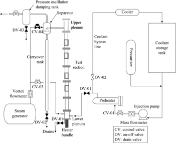
The effects of the spacer grid on the heat transfer enhancement have been investigated using a 6×6 square lattice rod bundle. shows a schematic diagram of the 6×6 rod bundle reflood test facility, advanced thermal hydraulic evaluation of reflood(ATHER) phenomena. The experimental facility consists of a test section, a separator, and a carryover tank for measuring the amount of entrained liquid droplet, a pressure oscillation damping system to control the system pressure, a coolant supply system, and a steam supply system. The test section consists of a 6×6 heater rod bundle, the flow housing, and lower and upper plenums. A single-phase steam generated in the steam generator is injected into the lower plenum and discharged to the atmosphere through the upper plenum. The principal operating conditions of the ATHER test facility are as follows:
Operating pressure: 0.1–1.0 MPa
Flooding velocity: 2–6 cm/s
Maximum heater rod surface temperature: 900 °C
Inlet subcooling: 20–80 °C
Maximum volumetric flow rate of steam: 0–140 m3/hr
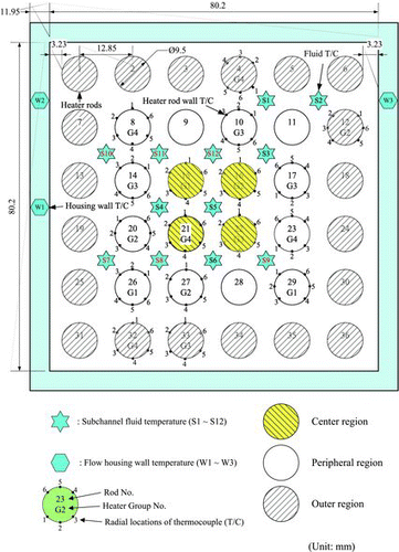
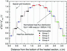
shows a cross-sectional view of the 6×6 rod bundle. The test section has a rectangular shape with an inner width of 80.2 mm and a wall thickness of 11.95 mm. A total of 11 spacer grids are installed to support the heater rods along the axial location in the test section. The spacer grids have the same geometry with those used in a Korean nuclear power plant, the Advanced Power Reactor 1400 MWe (APR1400). shows the top view and the unit grid configuration of the spacer grid used in the present experiment. The detailed information on the present spacer grid can be found in references [Citation11,12]. The heater rod bundle consists of 36 heater rods with the same outer diameter, pitch, and heated length with the fuel rods of the APR1400. The heater rods with thermocouples for measuring the surface temperatures are classified into the four groups. In the , G1, G2, G3, and G4 stand for the group numbers of the instrumented heater rods. The star symbols indicate the locations where the fluid temperatures are measured. The heated length and diameter of the heater rods are 3.81 m and 9.5 mm, respectively. The heater rods with a pitch of 12.85 mm are arranged in a 6×6 square array, and they are heated indirectly by AC power. shows the axial power distribution along the heater rods and the measurement elevations of the heater rod surface temperature. The sheath and the heating element of the heater rods are made of Inconel 600 and Nichrome, respectively. The heated section is divided into 15 steps to simulate a symmetric cosine axial heat flux profile. All the heater rods have the same power, and thus the radial power distribution is uniform.
Figure 4. Schematic diagram of the present spacer grid. (a) Top view of the spacer grid, and (b) Unit grid configuration [11,12].
![Figure 4. Schematic diagram of the present spacer grid. (a) Top view of the spacer grid, and (b) Unit grid configuration [11,12].](/cms/asset/3e811554-aa4b-44f9-94ca-13dbae1efa3a/tnst_a_881726_f0004_b.gif)
All components including the test section are well insulated to minimize heat losses to the outside air environment. The heat loss was estimated to be less than 1% of the total power under high power conditions. A heat balance was calculated to estimate the heat loss from the test section and to check a proper working of the test section instrumentation. The total power applied to the heater rods was compared with the enthalpy rise of the fluid through the test section. The parameter for the estimation of the heat balance at any elevation z was defined as follows:
(1)
where Q(z) is the total power up to an elevation z, is the mass flow rate, i(z) is the fluid enthalpy at the elevation z, and iin is the fluid enthalpy at the test section inlet. The experimental data which agree with the heat balance parameter within ±5% were only used in the analyses.
The effects of the radiation heat transfer to the flow housing were found to be negligible for the heater rods in the central region of the rod bundle, and the forced convection heat transfer was dominant over the radiation heat transfer for those heater rods in the central region. Therefore, the radiation effects on the measurement of the fluid temperatures were negligible in the present experimental conditions.
For instrumented heater rods, six K-type thermocouples with a sheath diameter of 0.5 mm are embedded on the outer surface of the heater rod to measure the heater rod surface temperature. The total number of thermocouples for measuring the surface temperatures of the heater rods is 102. A total of 15 K-type thermocouples with a sheath diameter of 1.0 mm are installed in subchannel centers at 11 axial locations along the heated section to measure the steam temperature. Three pairs of K-type thermocouples with a sheath diameter of 1.0 mm were installed to measure the inner and outer surface of the flow housing. shows the locations of the thermocouples, and the spacer grids. The single-phase pressure drops were measured using 10 differential pressure transmitters along the test section. shows the measurement locations of the differential pressure and the number of spacer grids in the span of the differential pressure transmitters.
Table 2. Axial locations of temperature measurements and spacer grids.
Table 3. Axial locations of differential pressure transmitters.
The steam flow rate was measured using a vortex flow meter located in the steam injection line. The pressures at the inlet and outlet plenums were measured using smart type pressure transducers. A total of 10 differential pressure transducers were installed along the test section to measure the differential pressures.
Based on a 95% level of confidence, the uncertainties of the measured data were estimated from the calibration of the measurement sensors and the accuracy of the related equipment. The maximum uncertainties of the measured data for the pressure, steam flow rate, and wall and steam temperatures are estimated to be less than ±1.5%, ±2.5%, ±1.9, and ±2.1 °C, respectively. The maximum uncertainties of the total power and heat flux are estimated to be less than ±2.1% and ±3.7%, respectively. The uncertainties of the Reynolds number of steam and the Nusselt number are less than ±5.4% and ±8.3%.
2.2. Experimental procedure and conditions
Slightly superheated steam enters the test section through the lower plenum, flows upward through the 6×6 rod bundle, and exits from the upper plenum. The system pressure was measured in the upper plenum and the mass flow rate of the steam was measured using a vortex flow meter installed just before the inlet nozzle to the lower plenum. The test parameters are the steam flow rate (i.e. Reynolds number of steam), system pressure, and the total power of heater rods. The heat transfer experiments in single-phase steam were carried out by the following procedures. The test parameters were kept at nearly constant values, and were allowed to stabilize for at least 30 minutes to achieve a steady-state condition before the recording of the test data. After that, the measured data such as the pressure, the steam temperature, the heater rod surface temperature, the steam flow rate, and the total power to the heater bundle were recorded, processed, and stored in a data acquisition and control unit.
A total of 276 local heat transfer data were obtained in the present experiment. The pressures at the exit of the test section were nearly atmospheric pressures. The inlet steam temperatures were at saturation or slightly superheated conditions. The Reynolds numbers of steam were 1121 to 13,160 at the inlet of the test section.
3. Experimental results and discussion
3.1. Heat transfer enhancement and pressure loss coefficient
The local Nusselt number was determined as
(2) with h the convective heat transfer coefficient, Dh the subchannel hydraulic diameter, and kv the thermal conductivity of steam. The heat transfer coefficient h can be calculated as follows:
(3) where q″ is the local heat flux, Tw is the surface temperature of heater rods, and Tv is the steam temperature. The local heat flux was calculated using the axial power distribution and the average heat flux as shown in .
In the present experimental conditions, the effect of the buoyance force on the heat transfer was negligible. The maximum Richardson numbers which indicate the relative importance of the natural convection compared with the forced convection were very small, less than 0.005. Thus, the effects of the natural convection on the local heat transfer were negligible compared with the effects of the forced convection. The heat transfer can be assumed to occur only by the forced convection.
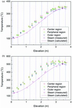
shows the axial variations of the wall and steam temperatures for typical test conditions of the present experiments. The wall temperatures in the center region (heater rod number 15, 16, 21, and 22 in ) are slightly higher than those in the outer region close to the flow housing. This lower temperature in the outer region might result from the possible radiation heat transfer between the heater rods in the outer region and the flow housing. Thus, the wall temperatures at the center region are only used in the following analyses. The measured steam temperatures agree well with the steam temperatures ideally calculated based on the heat balance. Therefore, it can be confirmed that the measured steam temperatures represent well the mixing cup temperature, and the heat loss to the outside air environment is negligible. At the top region of the heater rods, the wall temperatures slightly decrease or are nearly constant owing to the axial heat conduction into the unheated regions. The temperature difference between the heater rod and the steam are not large in the top and bottom regions of the heated length because the heat fluxes are very low in these regions. The small temperature difference can result in a large error of the calculated heat transfer coefficients, and thus data with small temperature differences were excluded in the analyses.
Figure 6. Axial temperature variations: (a) for the mass flow rate of 0.01 kg/s and total power of 5 kW and (b) for the mass flow rate of 0.05 kg/s and total power of 40 kW.
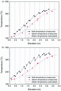
shows the axial variations of wall temperature of the heater rods in the central region and the steam temperature. In the figure, the dotted lines represent the top end locations of the spacer grids. The wall temperatures decrease while passing the spacer grids, indicating that the heat transfer was enhanced by the spacer grids. The wall temperatures increase again with the distance from the spacer grids owing to the decay of the heat transfer enhancement.
Figure 7. Average temperature variations: (a) for the mass flow rate of 0.015 kg/s and total power of 7 kW and (b) for the mass flow rate of 0.050 kg/s and total power of 20 kW.
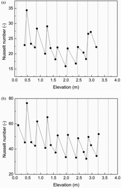
shows the axial variation of local Nusselt numbers where the heat transfer enhancement by the spacer grids is more evident. The local Nusselt number increases sharply while passing the spacer grids. After that, the heat transfer enhancement decreases as the distance from the spacer grids increases.
Figure 8. Nusselt number variations: (a) for the mass flow rate of 0.015 kg/s and total power of 7 kW and (b) for the mass flow rate of 0.050 kg/s and total power of 20 kW.
To obtain the pressure loss coefficient of the present spacer grid, the pressure drops were measured for single-phase water and steam flows. The single-phase pressure drop measured by a differential transmitter over the spacer grid consists of two components: frictional pressure drop of the bare rod bundle and the pressure drop by the spacer grid. The single-phase pressure drop can be calculated as follows:
(4) where ΔPt, ΔPbare, and ΔPsg are, respectively, the total pressure drop, frictional pressure drop of the bare rod bundle, and the pressure drop by the spacer grid. The frictional pressure drop of the bare rod bundle was obtained as
(5) where Lspan is the span between the measurement taps of the differential pressure, nsg is the number of spacer grids in the span, and Hsg is the height of the spacer grid. The subscript 0 means a reference differential pressure only with the bare rod bundle. The pressure drop of the bare rod bundle without a spacer grid, ΔPbare, 0, was measured by the differential pressure transmitter DPT-10, as shown in . Lspan, 0 is the span between the pressure measurement taps of DPT-10. The total pressure drop over the spacer grids, ΔPt, was measured by the differential pressure transmitter DPT-09. The pressure loss coefficient of the spacer grid, Ksg was obtained as
(6) where ρ is the fluid density and V is the fluid velocity.
Rehme [Citation5, Citation8] proposed that the single-phase pressure drop by a spacer grid can be related to the pressure loss coefficient of the spacer grid, Ksg, as follows:
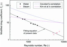
(7) where Cv is the modified drag coefficient and ϵ is the blockage ratio. The modified drag coefficient, Cv, has a weak dependency on the Reynolds number for Reynolds numbers of above 10,000. For honey-comb type spacer grids with square array, the modified drag coefficient has values of 6 to 7 for Reynolds numbers greater than 50,000.
shows the modified drag coefficient for the present spacer grid with the comparison with the conventional correlations by Cevolani [Citation13] and Kim et al. [Citation14]. The present experimental data can be correlated by the following equation:
(8)
3.2. Comparison with conventional correlations
In general, the conventional correlations have the following equation form to correlate the local heat transfer enhancement downstream of spacer grids:
(9) where Nu is the local Nusselt number at distance x from the downstream end of a spacer grid, Nu0 is the Nusselt number in a reference channel without spacer grids, i.e. a fully developed Nusselt number, and Dh is the hydraulic diameter. In addition, C1 represents the maximum single-phase heat transfer enhancement at the end of spacer grid, while C2 is associated with the decay of the heat transfer enhancement from its maximum value to the fully developed Nusselt number.
Marek and Rehme [Citation7] measured the heat transfer enhancement for a standard spacer grid in a triangular lattice array with air as a working fluid. They suggested the maximum heat transfer enhancement for a standard spacer grid as follows:
(10) where ϵ is the flow blockage ratio by the spacer grid.
Based on the above maximum heat transfer enhancement by Marek and Rehme, Yao et al. [Citation2, 3] proposed an exponential decay function to correlate the heat transfer enhancement downstream of a standard spacer grid design:
(11) As mentioned before, Yao et al.'s correlation was recommended for Reynolds numbers of above 10,000 and the flow blockages ratio from 0.15 to 0.34. Thus, it is not directly applicable to spacer grids with high blockage ratios, and for experimental conditions with Reynolds number of less than 10,000.
Groeneveld et al. [Citation9] proposed a correlation to predict an obstacle effect on the film-boiling heat transfer coefficient for the dispersed flow film-boiling region. The correlation can be expressed as follows:
(12) where xe is the equilibrium quality, and Ksg is the single-phase pressure loss coefficient of the spacer grid. For a single-phase steam flow by assuming thermodynamic equilibrium, Groeneveld et al.'s correlation becomes
(13) It should be noted that the single-phase steam is usually superheated while flowing through the heater rod bundle. Thus, Groeneveld et al.'s correlation basically cannot be directly applied to the present experimental conditions. However, the correlation was used for a qualitative comparison with the present experimental results.
Recently, Miller et al. [Citation10] found that the heat transfer enhancement is dependent on the Reynolds number as well as the blockage ratio. They developed a new correlation which includes the strong dependence of heat transfer on both the Reynolds number and the blockage ratio. Miller et al.'s correlation is as follows:
(14) Miller et al.'s correlation is based on the experimental data from relatively low flow blockage ratios ranging from 0.156 to 0.362.
In the present test section, the distances between spacer grids are about 400 mm and the hydraulic diameter is 12.63 mm. Thus, x/Dh for the distances between the spacer grids is about 31.7. A fully developed flow can be assumed to occur at points far from the end of the spacer grid prior to the next downstream of spacer grid. Previous experimental results showed that the spacer grid effects appear at x/Dh = −5 to −2 and disappear at x/Dh greater than about 20 [Citation3]. Hence, the region of x/Dh greater than 25 for each grid can be assumed to be an undisturbed region by each spacer grid. In addition, x/Dh of the fully developed flow should be slightly away from the next downstream spacer grid. Thus, the fully developed Nusselt numbers were obtained at an x/Dh of 26 far from the end of the spacer grid and slightly away from the next spacer grid.
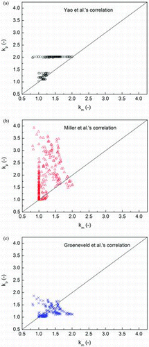
– compare the heat transfer enhancement factor obtained in the present experiment, Nu/Nu0, for spacer grid 4 with the conventional correlations. The top end of spacer grid 4 is located at 1.246 m from the bottom of the heated length. In (b), , and , the measured heat transfer enhancement factors for all spacer grids are plotted as a function of the dimensionless distance, x/Dh, where k stands for the heat transfer enhancement factor, Nu/Nu0. Subscripts “m” and “p” mean the measured and predicted values.
Figure 10. Prediction of Yao et al.'s correlation: (a) for spacer grid number 4 and (b) for the total data.
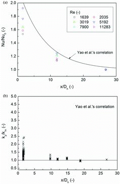
Figure 11. Prediction of Miller et al.'s correlation: (a) for spacer grid number 4 and (b) for the total data.
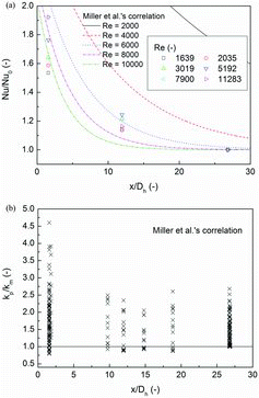
Figure 12. Prediction of Groeneveld et al.'s correlation: (a) for spacer grid number 4 and (b) for the total data.
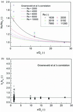
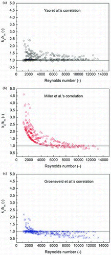
Yao et al.'s and Miller et al.'s correlations both overpredict the heat transfer enhancement at just the downstream end of the spacer grids at an x/Dh of 1.583. Groeneveld et al.'s correlation shows large scattering in the prediction accuracy at very low values of the dimensionless distance. As increasing the dimensionless distance, the predicted heat transfer enhancements by Yao et al.'s and Groeneveld et al.'s correlations approach the measured values. However, Miller et al.'s correlation still over-predicts the heat transfer enhancement regardless of the magnitude of the dimensionless distance.
shows the effect of the Reynolds number on the prediction of the heat transfer enhancement factor. For highly turbulent regions with high Reynolds numbers, Yao et al.'s and Miller et al.'s correlations show reasonable predictions of the heat transfer enhancement. Groeneveld et al.'s correlation shows slight under-predictions in highly turbulent regions. At low Reynolds numbers, Yao et al.'s and Groeneveld et al.'s correlations overpredict the heat transfer enhancement, while Miller et al.'s correlation significantly over-predicts the heat transfer enhancement. The predictions by Miller et al.'s correlation worsen when decreasing the Reynolds number to below about 4000. compares the measured heat transfer enhancement factor with the predicted values by the conventional correlations.
As pointed out above, the conventional correlations can be used to predict the heat transfer enhancement factor only for turbulent regions of high Reynolds number. Therefore, the conventional correlations should be improved at low Reynolds numbers performing more experiments using various spacer grids at low Reynolds number of less than 10,000. The poor predictions of the conventional correlations are attributed to the fact that the correlations were developed using experimental data obtained at relatively high Reynolds numbers of greater than 10,000. Thus, more experimental data should be obtained using various spacer grids at low Reynolds numbers of less than 10,000.
From the above comparison results, the correlation type including the pressure loss coefficient such as Groeneveld et al.'s correlation is more appropriate to predict the heat transfer enhancement by the spacer grids. Marek and Rehme [Citation7] suggested that the maximum heat transfer enhancement, C1, be equal to the pressure loss coefficient Ksg as follows:
(15) They proposed that the modified drag coefficient, Cv, has constant values of 6 to 7 for Reynolds numbers of greater than 10,000. As the Reynolds number decreases further below 10,000, the experimental data by Rehme [Citation8] show that the modified drag coefficient depends on the Reynolds number. For this reason, the maximum heat transfer enhancement may depend on the Reynolds number at low values.
Leung et al. [Citation16] pointed out that the single-phase pressure loss coefficient is a more generalized parameter than the blockage ratio. Applying the pressure loss coefficient of the spacer grids as a correlating parameter can provide better quantification of the spacer effect. They anticipated that the exponential decay function is also affected by the single-phase pressure loss coefficient.
Holloway et al. [Citation6] reported that Yao et al.'s correlation did not predict well the measured heat transfer enhancement for the split vane spacer grids with large blockage ratios. Yao et al.'s correlation over-predicted the maximum heat transfer enhancement factor at x/Dh = 0. The heat transfer enhancement rates for split vane spacer grids with large blockage ratios were smaller than those for standard grids with small blockage ratios. They concluded that the blockage ratio alone may not be an appropriate parameter for predicting the heat transfer enhancement. Thus, Holloway et al. developed a new correlation using the pressure loss coefficient of the spacer grid.
It is interesting to note that in , the heat transfer enhancement obtained in the present study increases when increasing the Reynolds number. The heat transfer enhancement factors are approaching to the predicted values by Yao et al. as increasing the Reynolds number. Meanwhile, Miller et al.'s and the Groeneveld et al.'s correlations predict a decrease of the heat transfer enhancement with an increasing Reynolds number, contrary to the present experimental results.
Figure 15. Effect of the Reynolds number on the heat transfer enhancement at spacer grid number 4 and x/Dh = 1.583.
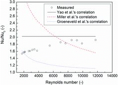
Although the experimental evidence is not clear, Yoder [Citation4] observed a similar trend as the present experimental results. He pointed out that the effect of the Reynolds number on the heat transfer enhancement depends on the relative magnitudes of the turbulences generated by the spacer grids and by the flow itself. At high Reynolds numbers, the heat transfer enhancement decreases with an increase in the Reynolds number. However, the opposite trends were observed at low Reynolds numbers, i.e. an increase of the heat transfer enhancement with increasing Reynolds numbers. This trend in the heat transfer enhancement at low Reynolds numbers is clearly shown in the present study.
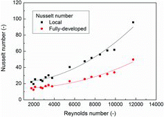
shows the effect of the Reynolds number on the local and the fully developed Nusselt numbers. The increasing rate of the local Nusselt numbers is larger than that in the fully developed Nusselt numbers, which implies an increase of the heat transfer enhancement factor with an increase in the Reynolds number.
Figure 16. Effect of the Reynolds number on the Nusselt numbers at spacer grid number 4 and x/Dh = 1.583.
As described in Section 1, the Reynolds numbers have low values of less than 10,000 in the early phase of the PWR reflood conditions. An accurate prediction of the heat transfer coefficient under single-phase steam conditions is crucial for a reliable prediction of the fuel rod surface temperature. This prediction capability has a strong influence on the prediction of the peak cladding temperature (PCT), which is the one of the most important safety criteria for the LOCA. As observed from the present study, the conventional correlations show poor predictions of the heat transfer enhancement by spacer grids especially at low Reynolds numbers. Furthermore, the conventional correlations do not properly account for the effects of the Reynolds numbers on the heat transfer enhancement. Thus, more systematic experiments should be performed using various spacer grids with large blockage ratios at low Reynolds numbers, considering the early phase of the PWR reflood conditions.
4. Conclusions
An experimental study in a 6×6 rod bundle has been performed to investigate the effects of spacer grids on the single-phase convective heat transfer enhancement in laminar and turbulent flows under PWR reflood conditions. The experimental data show that the Reynolds number has a significant impact on the heat transfer enhancement when the Reynolds number is lower than about 10,000.
The conventional correlations show poor predictions of the heat transfer enhancement by spacer grids at low Reynolds numbers. In particular, the maximum heat transfer rate at the top end of the spacer grids was significantly overestimated. Furthermore, the conventional correlations do not properly account for the effects of the Reynolds numbers on the heat transfer enhancement. The poor prediction of the conventional correlations results from the fact that the correlations were developed based on experimental data obtained for spacer grids with a relatively low blockage ratio and for relatively high Reynolds number of greater than 10,000. Thus, to improve the conventional correlations, more systematic experiments should be performed using various spacer grids with large blockage ratios at low Reynolds numbers, considering the early phase of the PWR reflood conditions.
Nomenclature
| C1 | = | fitting coefficient representing the maximum heat transfer enhancement |
| C2 | = | fitting coefficient representing the decay of the heat transfer enhancement |
| Cv | = | modified drag coefficient of the spacer grid |
| Dh | = | hydraulic diameter (m) |
| Hsg | = | height of the spacer grid (m) |
| h | = | heat transfer coefficient (kW/m2-K) |
| i | = | fluid enthalpy (kJ/kg) |
| Ksg | = | single-phase pressure loss coefficient of spacer grid |
| k | = | heat transfer enhancement factor, Nu/Nu0 |
| kv | = | thermal conductivity of steam (kW/m-K) |
| Lspan | = | axial span between the measurement taps of a differential pressure transmitters (m) |
| = | mass flow rate of steam (kg/s) | |
| nsg | = | number of spacer grids in the axial span of a differential pressure transmitters |
| Nu | = | local Nusselt number |
| Nu0 | = | fully developed Nusselt number |
| Q(z) | = | total power of the heater rods up to elevation z (kW) |
| q″ | = | local heat flux (kW/m2) |
| Re | = | Reynolds number, ρvVDh/μv (-) |
| Tw | = | surface temperature (K) |
| Tv | = | steam temperature (K) |
| V | = | flow velocity (m/s) |
| x | = | axial distance from the downstream end of the spacer grid (m) |
| xe | = | equilibrium quality |
| z | = | axial distance along the heated section from the bottom of the heated length (m) |
Greeks
| ΔPsg | = | pressure drop by the spacer grid (Pa) |
| ΔPt | = | total pressure drop (Pa) |
| ΔPbare | = | frictional pressure drop of the bare rod bundle (Pa) |
| ϵ | = | blockage ratio |
| η | = | heat balance parameter |
| μv | = | viscosity of steam (N-s/m2) |
| ρv | = | density of steam (kg/m3) |
Subscripts
| 0 | = | reference point for the differential pressure or fully developed |
| in | = | test section inlet |
| m | = | measured |
| p | = | predicted |
| v | = | vapor or steam |
| w | = | wall |
Additional information
Funding
References
- Stosic Z. On the role of spacer grids on conditions of dryout/rewetting and local thermal hydraulics in boiling water reactors. Paper presented at: Proc. of the 9th Int. Topical Meeting on Nuclear Reactor Thermal Hydraulics (NURETH-9); 1999 Oct 3–8; San Francisco, CA. [CD-ROM].
- Yao SC, Hochreiter LE, Leech WJ. Heat transfer augmentation in rod bundles near grid spacers. Paper presented at: ASME Winter Annual Meeting; 1980 Nov 16–21; Chicago, IL.
- Yao SC, Hochreiter LE, Leech WJ. Heat-transfer augmentation in rod bundles near grid spacers. J Heat Transfer. 1982;104:76–81.
- Yoder GL. Heat transfer near spacer grids in rod bundles. Paper presented at: National Heat Transfer Conf.; 1985 Aug 4–7; Denver, CO.
- Rehme K. Pressure drop of spacer grids in smooth and roughened rod bundles. Nucl Technol. 1977;31:314–317.
- Holloway MV, McClusky HL, Beasley DE, Conner ME. The effect of support grid features on local, single-phase heat transfer measurements in rod bundles. J Heat Transfer. 2004;126:43–53.
- Marek J, Rehme K. Heat transfer in smooth and roughened rod bundles near spacer grids. Paper presented at: ASME Winter Annual Meeting; 1979 Dec 2–7; New York, NY. p. 163–170.
- Rehme K. Pressure drop correlations for fuel element spacers. Nucl Technol. 1973;17:15–23.
- Groeneveld DC, Leung LKH, Zhang J, Cheng SC, Vasic A. Effect of appendages on film-boiling heat transfer in tubes. Paper presented at: Proc. of the 9th Inter. Topical Meeting on Nuclear Reactor Thermal Hydraulics (NURETH-9); 1999 Oct 3–8; San Francisco, CA. [CD-ROM].
- Miller D, Cheung FB, Bajork SM. On the development of a grid-enhanced single-phase convective heat transfer correlation. Paper presented at: Proc of the 14th Inter Topical Meeting on Nuclear Reactor Thermal-hydraulics (NURETH-14); 2011 Sep 25–30; Toronto, Canada [CD-ROM].
- Kim YH, Jang YK, Kim KT. Advanced spacer grid design for the PLUS7 fuel assembly. Paper presented at: Proc. of the 3rd Korea-Japan Symposium on Nuclear Thermal Hydraulics and Safety (NTHAS3); 2002 Oct 13–16; Gyeongju, Korea. [CD-ROM].
- Kim KT, Jang YK, Kim JI. In-reactor performance of an advanced PWR fuel, PLUS7, for OPR1000s in Korea. J Nucl Sci Tech. 2008;45:836–849.
- Cevolani S. ENEA thermodynamic data base for the advanced water cooled reactor analysis. Paper presented at: 1st Research Co-ordination Meeting of IAEA CRP on Thermodynamic Relationship for Advanced Water Cooled Reactors; 1995 Sep 5–8; Vienna, Austria.
- Kim NH, Lee SK, Moon KS. Elementary model to predict the pressure loss across a spacer grid without a mixing vane. Nucl Tech. 1992;98:349–353.
- Kakac, S, Shah RK, Aung W. Handbook of single-phase convective heat transfer. New York (NY): Wiley; 1978.
- Leung LKH, Groeneveld DC, Zhang J. Prediction of the obstacle effect on film-boiling heat transfer. Nucl Eng Des. 2005;235:687–700.

