Abstract
The flow and thermal non-uniformities occurring in the intermediate heat exchanger (IHX) of a liquid metal-cooled fast breeder reactor have been characterized through numerical simulations. For modeling the primary and secondary sodium flow through the IHX, an equivalent anisotropic porous medium approach has been used. The pressure drop in the equivalent porous medium is accounted through the inclusion of additional pressure drop terms in the Navier–Stokes equations, with the help of standard correlations for cross flow or parallel flow over tubes. For secondary sodium flow, the effects of a flow distributor device with orifices and baffles at the inlet have also been included, in addition to axial flow through the tubes. The heat exchange between primary and secondary streams is incorporated in the form of a volumetric heat source or sink term, which is corrected iteratively. The resulting flow distributions are in reasonable agreement with available experimental results. The study shows that the temperature of the secondary sodium flow at the exit can be made more uniform by exchanging less heat near the inner wall of IHX, as compared to the region close to the outer wall, using suitable flow distribution devices.
1. Introduction
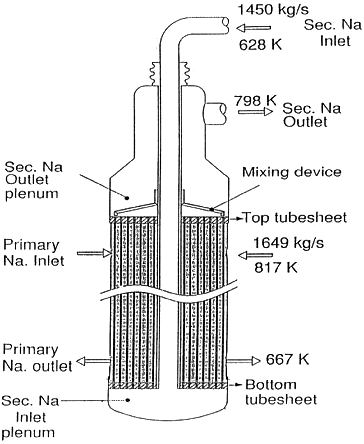
The intermediate heat exchanger (IHX) of a liquid metal-cooled fast breeder reactor (LMFBR) involves the heat exchange between radioactive primary sodium and non-radioactive secondary sodium, flowing on the shell and tube sides, respectively, as shown in . After receiving the heat generated in reactor core, the primary sodium enters the IHX radially through an annular inlet, turns into an axial flow and finally exits radially through an annular exit at the bottom of IHX on the shell side. The non-radioactive secondary sodium flows inside a downcomer and turns by 180o to distribute into a large number of vertical stainless steel tubes at the bottom side of the IHX. It exchanges heat with the primary sodium within IHX and eventually carries this heat to the steam generation cycle. The predominantly counter flow heat exchange () between the primary and secondary streams results in an effective heat transfer. However, the corresponding velocity distributions of liquid sodium are not uniform on shell/tube sides of the heat exchanger; such mal-distribution of flow results in significant temperature variation in the radial direction for the secondary sodium that exits from the IHX. Since the tubes carrying secondary sodium are very long, large radial variation of temperature can result in differential thermal expansion of the tubes. To reduce the resulting thermal stresses, a proposed design criterion is that the radial variation of temperature across the secondary sodium tubes should be limited to 20 K at the exit. A flow distributor device is placed on the inlet side for achieving the desired secondary flow distribution for reducing the radial temperature variation. This is complemented by a mixing device for secondary sodium at the exit of the IHX ().
Figure 2. Schematic diagram for the flow configuration of primary and secondary flow configuration and equivalent porous medium model.
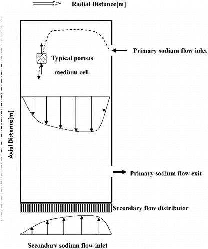
The primary sodium flow in the IHX tends to have larger flow velocity adjacent to the outer periphery of the heat exchanger due to a flow short-circuiting or channeling effect [Citation1]. The secondary sodium which flows through the downcomer undergoes a sharp turn within the inlet plenum. The large pressure drop for the flow-turning process generates a non-uniform flow of the secondary sodium also, with larger amount of flow biased towards the outer periphery (). However, the resulting flow mal-distributions of sodium in the shell and tube sides are not matched properly and this gives rise to a non-uniform heat exchange. As a consequence, the maximum radial variation of temperature in the secondary sodium leaving the IHX at the top may not be limited to 20 K, as per the design criterion. The proposed methodology for achieving this constraint involves the inclusion of an appropriate flow distributor at the bottom portion of IHX, which suitably modifies the secondary sodium flow distribution in accordance with the primary sodium flow, in order to achieve a nearly uniform exit temperature of secondary sodium [Citation2,3].
Only a few studies are available in the open literature, which consider the heat transfer aspects in the sodium–sodium intermediate heat exchanger of a fast breeder reactor. Heat transfer in the tube bundle of an intermediate heat exchanger was investigated by Aburomia et al. [Citation4]. The authors noted the effects of mal-distribution on the temperature distributions of both the tube and shell sides. Thermal hydraulic studies on the sodium-cooled reactor facilities (BN-1200, BN-600 and so on) were reported by Mitenkov et al. [Citation5] and Poplavskii et al. [Citation6]. Mitenkov et al. [Citation5] modeled the intermediate exchanger in BN-600 facility using a porous body formulation with anisotropic properties and different velocity/temperature profiles at the entrance windows. These theoretical and experimental studies indicate that uneven flow development of primary sodium in the inter-tube space gives rise to a decrease in the overall heat transfer efficiency [Citation6]. Padmakumar et al. [Citation2] experimentally measured the velocity distribution with and without flow distribution devices in the IHX of LMFBR. Gajapathy et al. [Citation3] numerically predicted the flow and temperature distributions in the IHX for the cases with and without flow distribution devices.
A detailed flow and thermal analysis of the IHX demands the use of a three-dimensional (3D) model. However, given the fact that there are several thousands of secondary sodium tubes in a typical IHX, a complete 3D model is extremely time consuming. Therefore, it is desired to employ a simplified porous medium model that can capture the flow and heat exchange phenomena with reasonable accuracy. The exchange of heat between the primary and secondary streams in a small control volume cell could have a cross flow or counter flow configuration, depending on the location of the cell (). Therefore, it is not possible to apply one-dimensional models for obtaining the temperature field variation in the primary or secondary sodium streams. The porous medium approach has been employed for studying the flow and associated heat transfer between solid and fluid media in various practical problems [Citation1,Citation7–9]. Khan et al. [Citation10] illustrated the applications of the porous medium flow approximation for predicting the temperature distribution in fuel rod subassemblies. Domanus et al. [Citation11] employed the porous medium approach with distributed resistance, anisotropic surface permeability and distributed heat sources to model the thermal hydraulics of fuel subassemblies. Nithiarasu et al. [Citation8] have shown the occurrence of flow channeling in a variable porosity medium, which is similar to the short circuiting of flow in the shell side of IHX in the present problem. Mal-distribution effects in the flow entering various subchannels from a plenum have been addressed by Kumaragurubaran et al. [Citation12], in the context of micro-channel heat sinks. Very few studies are available at present which investigate the effects of flow and mal-distribution on the heat transfer between the primary and secondary sodium streams of an IHX.
In the present study, a decoupled approach is employed first to separately analyze the flow and temperature fields of the primary and secondary sodium streams, by prescribing a volumetric heat source or sink, respectively. Calculations have been carried out for a uniform heat source/sink initially; later, a heat source (or sink) which has radial and axial variations has been considered. The objective of such an approach is to arrive at an ideal heat source/sink distribution which can lead to a uniform exit temperature for the secondary sodium. An iterative coupled analysis is finally implemented in which the actual heat source/sink distributions are arrived at, by assuming the heat transfer to be proportional to the local temperature difference between the sodium streams. The effects of introducing a flow distribution device on the secondary exit temperature distribution are also highlighted.
2. Theoretical model
The Indira Gandhi Centre for Atomic Research (IGCAR) is involved at present in the construction of a 500 MWe pool-type liquid sodium-cooled fast breeder reactor. The reactor consists of four intermediate heat exchangers, where heat is transferred from the radioactive primary sodium to the secondary sodium flowing inside vertical stainless steel tubes (). The rate of total heat transfer in each IHX is about 315 MW and 3600 tubes carry the secondary sodium for transferring this heat to the steam cycle. In view of the complex geometry, the problem is approximated in terms of an equivalent porous medium, through which two immiscible fluids (primary and secondary sodium) pass and exchange heat. The equivalent flow resistance for the array of tubes has been prescribed appropriately for the cross flow and parallel flow external to the tubes as well as the flow inside the tubes, from the correlations available in the literature [Citation2,3,Citation9].
In the equivalent porous medium approach, the volumetric heat exchange between the two streams is treated as unknown which is corrected iteratively using the basic energy balance equation over a unit volume cell given by
(1)
In the above equation, represents the volumetric sodium flow rate through a typical cell (), C is the specific heat of sodium, ΔT is the temperature variation of the flow stream across the cell, H is the overall volumetric heat transfer coefficient (in W m−3) and
is the volumetric heat transfer rate between the two streams. Also, the subscripts ‘p’ and ‘s’ represent quantities corresponding to the primary and secondary streams. Here,
is primarily a function of radial and axial directions, assuming symmetry about the axis of IHX. Thus,
(2) The amount of heat exchange between the two streams is affected mainly by the mass flow distribution of the primary and secondary sodium flows.
Alternatively, from Equation (1), it can be shown that the volumetric heat transfer rate is proportional to the local temperature difference between the primary and secondary sodium streams. Due to the fact that the thermal conductivity of sodium is very high, the overall heat transfer coefficient H is only a very weak function of the primary and secondary stream velocities (it is dominated by conduction heat transfer) and hence H can be approximated as a constant. Using a constant value for H, the source/sink term can be iteratively corrected until
α (Tp − Ts).
In order to achieve the overall objective of restricting the radial temperature variation on the secondary side to less than 20 K, suitable flow distribution devices have to be placed at the inlet of the secondary stream into the IHX, to modify the secondary sodium flow distribution as desired. The overall desired heat transfer rate between the two sodium streams of the IHX is 315 MW. Given the total mass flow rates of sodium on the primary and secondary sides and the corresponding inlet temperatures, the average fluid temperatures at the exit can be calculated for both the streams. However, the task at hand is to minimize the radial variation of secondary sodium flow temperature by suitably redistributing the mass flow distribution of secondary sodium through the tubes.
The primary sodium flow through the IHX is modeled as an axi-symmetric steady flow through an anisotropic porous medium, since the flow resistances for the external flow over the tubes in the axial and radial directions are quite different. The governing equations for the problem are given by the incompressible Navier–Stokes equations in terms of axial and radial coordinates (z, r). The buoyancy term due to density variation is simplified via the Boussinesq approximation. The secondary sodium flow has also been modeled by the same approach using a very large flow resistance in the radial direction in order to render the flow axial in the tube region. The equations considered in the analysis are given below.
Continuity equation:
(3)
z-momentum equation:
(4)
r-momentum equation:
(5)
Energy equation:
(6) where
= heat sink (or source) per unit volume per unit time in W m−3. Equations (3)–(6) represent the governing equations for flow and heat transfer in the IHX region, modeled by the equivalent porous medium approach. However, for providing appropriate inlet conditions for the secondary sodium, the flow domain has been extended to include the downcomer and plenum region, as shown in . For the downcomer and plenum zones, the governing equations have been simplified by removing the additional sources/sink terms corresponding to the porous medium model. Also, due to large Reynolds number (order of 106) of the flow, the standard k – ϵ turbulence model has been implemented to arrive at the effective viscosity and thermal conductivity of the flow in these regions.
A special feature of the present solution methodology is the manner in which heat balance is achieved in the primary and secondary sodium streams. These two streams do not mix physically as they flow on the shell and tube sides of the IHX. However, heat is exchanged across the tube walls, which can be accounted in terms of the volumetric heat source or sink term in Equation (6). In terms of an overall volumetric heat transfer coefficient H, the source/sink terms can be expressed as
= H (Tp − Ts), where Tp and Ts are the local bulk temperatures of the primary and secondary sodium streams, respectively. For liquid sodium whose thermal conductivity is quite high, the heat transfer coefficient primarily depends on conduction heat transfer and hence it can be taken essentially as a constant [Citation3]. In other words,
is directly proportional to (Tp − Ts). Starting from a uniform heat flux distribution for the primary and secondary sides, the radial and axial variations are iteratively introduced until the above proportionality between the volumetric heat source and the temperature difference (Tp − Ts) is satisfied.
In the porous medium model, the effects due to the tubes have been incorporated by introducing an additional pressure drop term in the Navier–Stokes equations having the form,
(7)
Such a generalized non-Darcy model for loosely packed porous media was first developed by Nithiarasu et al. [Citation8]. The first term on the right-hand side of Equation (7) represents the viscous drag and the second term corresponds to the form drag, arising due to the presence of the tube bank. The values of constants C1 and C2 are taken depending upon the flow direction (i.e. cross flow or flow parallel to the axis of the tubes). The values of C1 and C2 depend on the tube diameter, the pitch between the tubes and the arrangement (staggered or in-line). The above-mentioned porous medium model is separately employed for the primary sodium and the secondary sodium flows, to predict the volume-averaged, local velocity distributions. Since the secondary sodium flow is essentially in the axial direction inside the IHX, very large values of the resistance coefficients C1 and C2 have been employed to make the flow velocities in the radial direction negligibly small within the tube region.
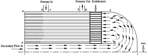
In the present study, a decoupled approach has been first employed to separately analyze the flow and temperature fields of primary and secondary sodium, by prescribing a volumetric heat source (for secondary stream) or a heat sink (for primary stream) appropriately. Calculations have been carried out for a uniform heat source or sink of magnitude 1.7 × 10⁷ W m−3, which corresponds to a total heat transfer rate of about 315 MW in the IHX. Later, heat source (or sink), which has radial and axial variations, has been considered. After the decoupled analysis, a coupled analysis has been presented where the actual heat source/sink distribution is arrived at by iteratively correcting until it becomes proportional to the temperature difference (Tp − Ts). This coupled exercise has been performed by analyzing a whole range of primary and secondary flow and thermal fields and identifying the combination for which Equation (1) is closely satisfied. The IHX flow geometry and boundary conditions employed are shown in . The input details for both primary and secondary sodium flows are defined in .
Table 1. Input data for the simulations.
Referring to , the boundary conditions for the analysis are: primary sodium inlet on surface GF; primary flow outlet on surface ED; secondary flow inlet on surface AI; secondary flow outlet on surface AH; axis of symmetry on line IJ; no slip wall condition on surfaces HG, FE, DCJ and AB.
2.1. Decoupled analysis – modeling of primary side
A simulation of steady primary flow of sodium through the IHX has been carried out. The annular region of IHX (which consists of tubes carrying secondary sodium) is assumed to be an anisotropic porous medium. The additional pressure drop terms due to the presence of tubes have been modeled using the viscous resistance and inertial resistance coefficients (C1 and C2) in the porous medium formulation. For the axial direction, these coefficients have been derived from turbulent flow correlations [Citation13] in terms of the hydraulic diameter for the inter-tube gap. The commercial computational fluid dynamics (CFD) software FLUENT is employed for the numerical simulations. User-defined functions have been employed for specifying the additional pressure gradient (pressure drop per unit length, Pa m−1) in the form , where
is the inertial resistance coefficient,
is the viscous resistance coefficient and ub is the superficial flow velocity in the axial direction. The values of C1 and C2 are different for the radial and axial directions due to the difference in the flow geometry. For the radial direction, the correlations of Zhukauskas and Ulinskas [Citation14] for cross flow over staggered tube banks are employed. A uniform heat sink of
W m−3 is employed for modeling the thermal field with all the external boundaries being treated as adiabatic.
2.2. Decoupled analysis – modeling of secondary side
As done in the case of primary sodium flow, the porous medium resistance coefficients C1 and C2 have been obtained from relevant pressure drop correlations for turbulent flow through tubes in the axial direction. Since no flow is possible in the radial direction inside the tubes, the values of C1 and C2 have been set as several orders of magnitude higher than the corresponding axial values (which will render the radial velocity values close to zero within the tubes). The thermal problem is handled by prescribing a uniform volumetric heat source of W m−3, with all external surfaces of the IHX being treated as adiabatic.
2.3. Coupled analysis
In the coupled analysis, the heat source/sink term alone needs to be treated as an unknown which is corrected iteratively, with the flow modeling remaining the same as before. The predicted flow fields also may not be significantly different, except for minor changes due to buoyancy effects (which are influenced by the temperature field). In general, the heat source/sink term can be expressed as
(8) For the decoupled analysis in which uniform source/sink was considered, the radial and axial functions f(r) and g(z) are both assumed as unity and the value of Qo is set as equal to 1.7 × 10⁷ W m−3. For the next level of approximation, a radially increasing function f(r) is considered, for simulating the effect of more flow being pushed towards the outer periphery of the IHX on both the primary and secondary sides. Although f(r) could in general be expressed as a polynomial of the radial coordinate, a simpler expression has been considered for highlighting the effect of the heat source/sink term. This has been assumed in the form
(9) where Ri and Ro are the inner and outer radius values for the annular region and Qo is the heat sink value (equal to −1.7 × 10⁷ W m−3) for the uniform case. Here, the axial function g(z) has been set as unity. Also, α is a parameter varying between 0 and 1, with α = 1 corresponding to the uniform heat removal case. The cases with α ≠ 1 pertain to the situation when heat sink value is minimum at Ri and it increases with radius. The form of Equation (9) has been selected such that it is compatible with the assumption of axi-symmetry and has the same amount of total heat transfer as the uniform case. Results have been predicted by systematically varying the parameter α in the range 0–1.
The axial variation of the heat source/sink mainly arises due to the fact that the mass flow rates of the primary and secondary sodium streams are not equal (refer and ). In fact, the temperature differences between the two streams at the top and bottom portions of the IHX are also not equal due to this reason. It can be seen that the bulk temperature difference between the two streams at the top of the IHX is given as ΔTtop = 817 − 798 = 19 K and at the bottom of the IHX as ΔTbottom = 667 − 627 = 40 K. Thus, even proposing a linear expression of the form
(10)
can incorporate the axial variation of the heat transfer, since the heat source/sink term has been shown to be approximately proportional to the local difference between Tp and Ts. The simplified expressions given by Equations (9) and (10) are able to incorporate both the radial and axial variations of the heat transfer rate due to both flow mal-distribution and the difference in mass flow rates of the primary and secondary streams. Numerical simulations show that the ratio of becomes nearly uniform even with these simple functional forms. Adding one or two more terms in the polynomial expansions of f(r) and g(z) can make the proportionality between the heat source/sink and local temperature difference (Tp − Ts) even closer. With this coupled approach, the effects of including a flow distributor at the inlet and a mixing device at the exit of the secondary stream have been carried out, in order to meet the design specification for the maximum radial variation of temperature for the secondary sodium.
3. Results and discussions
3.1. Decoupled analysis with uniform heat source/sink
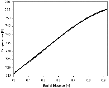
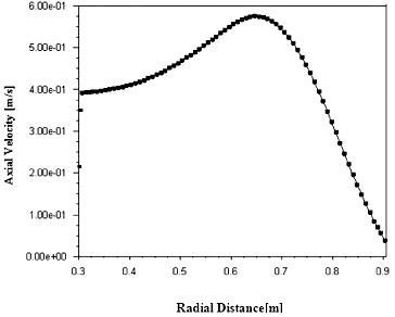
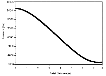
The predicted velocity vectors ((a)–(c)) indicate that flow is highly non-uniform for a short distance near the inlet and outlet of the primary sodium flow, with both radial and axial components existing due to flow-turning. However, in the mid-portion of the IHX, flow is primarily in axial direction and nearly uniform, except in the regions close to the walls. The velocity vectors enter radially at the inlet and they become completely axial, within an axial distance of about a meter. Similarly, turning of the vectors in the radial direction is observed close to the primary outlet also. The radial distribution of axial velocity at a section just below the primary inlet () shows the extent of flow mal-distribution and the short-circuiting effect occurring near the outer wall of the IHX. The axial pressure distribution () also exhibits a nearly linear pressure drop in the bulk of the IHX indicating an approach towards developed flow with radial velocity component becoming zero. Using these flow predictions and assuming a uniform volumetric heat removal rate by secondary sodium (for a total heat transfer of 315 MW), the temperature variation has been predicted in the radial direction at middle section (). As a consequence of flow mal-distribution, the primary sodium temperature varies in the range of 718–755 K in the radial direction, if a uniform heat sink is assumed. Therefore, non-uniform heat removal (more heat transfer near the outer wall) is required to reduce the radial temperature variation of the primary sodium stream.
Figure 4. Velocity vectors of primary sodium flow: (a) Velocity vectors at inlet region. (b) Velocity vectors at middle region. (c) Velocity vectors at outlet region.
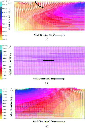
Figure 7. Radial variation of primary sodium temperature at mid-section for α = 1.0 (uniform heat sink).
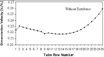
illustrates the radial variation in the secondary sodium velocity (in axial direction) when there is no flow distributor device. The dimensionless velocity is observed to vary in the range 0.224–0.255, for this case. The reason for such a flow mal-distribution is the existence of a large recirculation vortex in the plenum region, following the 180o turn undergone by the secondary sodium when it exits from the downcomer. To achieve the desired secondary flow within the tubes for reducing the radial variation of temperature, it is necessary to break the recirculatory vortex with the help of some baffles and also divert some flow towards the outer region by introducing orifices [Citation3].
3.2. Coupled analysis with variable heat source/sink
To reduce the temperature variation in primary sodium (which may induce a similar non-uniform radial temperature variation in the secondary sodium), a non-uniform heat removal rate has been assumed in the radial direction for the same overall heat transfer rate of 315 MW. For this purpose, the volumetric heat sink value has been taken to be less near the inner wall as compared to that near the outer wall, with a quadratic variation with radial distance (as per Equation (9)).
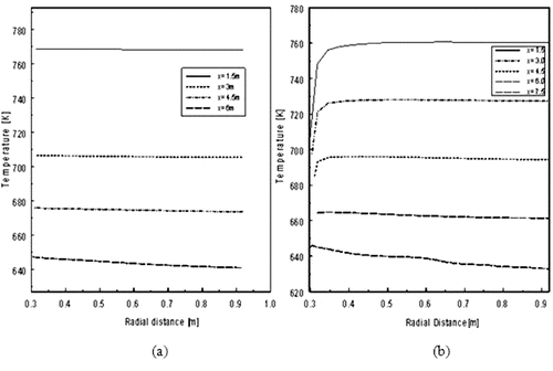
The effect of introducing a non-uniform heat source/sink is shown in . Here, the secondary sodium temperatures for the cases of uniform source (α = 1) and non-uniform source (α = 0.8) are shown. It is evident that for a major portion of the heat exchanger, the radial variation of the secondary sodium temperature reduces significantly if the heat source is non-uniform, i.e. more heat removal near the outer periphery. The variation of primary sodium temperature (not shown here) also reduces correspondingly.
Figure 9. Temperature distribution in secondary flow. (a) Non-uniform source (α = 0.8). (b) Uniform source (α = 1.0).
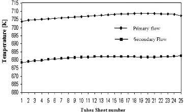
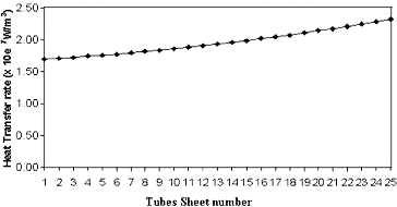
In a fully coupled study, both the radial and axial variations of heat source/sink are introduced using the functions of f(r) and g(z); in particular, the value of α has been varied from 0 to 1. It was observed that the volumetric heating rate is nearly proportional to the local temperature difference at different axial locations, for a value of α ∼ 0.8. The corresponding radial variations of the primary and secondary sodium temperatures and the heat source/sink are shown in and , respectively. A similar approach has been followed for the cases with flow distributor also, to find the value of α which gives the best match of the heat source/sink variation which is proportional to the temperature difference ΔT.
3.3. Validation of porous medium model
Before proceeding with the simulations corresponding to the cases with a flow distributor, it was felt necessary to validate the results of the current porous medium model with some experimental results available in the literature. The natural convective flow and heat transfer in a differentially heated cylindrical annulus has been experimentally studied by Prasad and Kulacki [Citation15]. For this simulation, the top and bottom walls of the annular enclosure are treated as adiabatic and the inner/outer curved surfaces are assumed to have prescribed values of temperature. Predictions were made for the Raleigh number range of 8 × 10⁶ < Ra< 3 × 10¹⁰, and a Prandtl number range of 4 < Pr < 196. The Rayleigh number Ra is based on the annular gap as the length scale, involving the permeability of the porous medium and the temperature difference between the hot and cold walls, similar to the work of Prasad and Kulacki [Citation15]. Although these experimental results correspond to a high Prandtl number situation, comparison has been presented with the predictions of the porous medium model adopted here, since no experimental data are available for liquid sodium applications in free literature. The predicted results in this range agree excellently with the experimental results of Prasad and Kulacki [Citation15], as shown in .
3.4. Effects due to inclusion of flow distributor
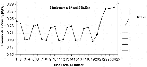
The flow distributor (which consists of orifices) provides additional resistance to the flow through the inner rows. To arrive at the optimal distributor configuration, the number of rows covered by the distributor is varied. Also, for controlling the size of the recirculation zone, some baffles have been introduced below the distributor. A typical result corresponding to the case of 19 distributor orifices and five baffles (to break the recirculation vortex) is shown in . It is seen from the figure that due to the combined effect of the flow distributor and baffles, the average velocity of the flow entering through the inner rows of tubes reduces and it is diverted towards the outer rows. In fact, the dimensionless velocity reduces to about 0.21 for the inner rows and it increases to a value of about 0.28 for the outer rows of tubes.
Experiments have been carried out using water model [Citation2] with or without flow distribution devices. After detailed study of experimental results, the authors [2] arrived at an optimal device for redistributing the secondary fluid flow to correct mal-distribution effects in the IHX configuration. Present simulations have also been extended to the same distribution device geometry. The measured velocity distribution among various rows of tubes, normalized with respect to the downcomer velocity, is shown in and compared with present predictions. It is clear that the computational results match reasonably well with experimental measurements.
Figure 14. Comparison between experimental and present computational results (solid line: computational; broken line: experimental [2]). (a) Without distributor. (b) With distributor.
![Figure 14. Comparison between experimental and present computational results (solid line: computational; broken line: experimental [2]). (a) Without distributor. (b) With distributor.](/cms/asset/8159b737-387e-4923-af77-3ae14799520f/tnst_a_903812_f0014_oc.jpg)
The minor deviations observed in the velocity distribution can be attributed to the fact that the present predictions pertain to liquid sodium while those of the experiments are for a water model. Also, the Reynolds number values for the two investigations are quite different, although both are in the turbulent regime.
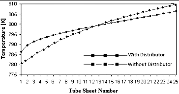
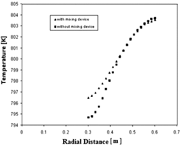
The temperature profile at the tube bundle exit with and without flow distributor is shown in . It is evident that the temperature variation for the secondary sodium at the exit is about 30°C when no flow distributor is present. If a flow distributor of 19 rows width and five baffles is included, the temperature variation at the exit of the tube bundle reduces to about 20 °C, which is within the acceptable limits. However, in order to bring down the radial temperature variation further, a mixing device has been introduced downstream of the tube bundle (apart from the flow distributor), as shown in . The effect of the mixing device is highlighted by comparing the radial temperature profiles just before the IHX outlet, for the cases with and without the mixing device (). Since the mixing device brings hot secondary sodium from the outer periphery region to the relatively colder inner periphery region, the additional mixing further reduces the radial temperature variation at the IHX exit from 10 °C (i.e. 804–794 K) to about 7 °C (i.e. 803–796 K).
4. Conclusion
The present study highlights the flow mal-distribution effects on both the primary and secondary sodium streams of the IHX in a sodium-cooled fast breeder reactor. Primary sodium exhibits a short-circuiting effect, as the flow on the shell side turns axial after radial entry; as a consequence, more mass flow is diverted to the outer regions of the IHX. For the secondary sodium, the velocity profile is non-uniform due to the presence of a recirculatory vortex in the header region. The presence of a flow distributor with baffles at secondary inlet helps to modify the velocity distribution and divert more secondary sodium flow through the outer rows of tubes. A coupled non-uniform heat source/sink model with an equivalent porous medium approach has been developed in the present study to effectively analyze the flow and thermal effects due to flow mal-distribution on both the primary and secondary sides. The porous medium model with non-uniform heat exchange shows that modified secondary flow distribution with the help of a flow distributor can compensate for the mal-distribution of primary sodium on the shell side. With the help of flow distributor device, it is possible to limit the radial variation of secondary sodium temperature within acceptable limits. Additional mixing provided by a mixing device downstream of the tube bundle can reduce the radial variation of secondary sodium temperature further.
Nomenclature
| Cp | = | Specific heat capacity (kJ kg−1 K−1) |
| dh | = | Hydraulic diameter (m) |
| f | = | Friction factor |
| g | = | Acceleration due to gravity (m s−2) |
| k | = | Thermal conductivity (W m−1 K−1) |
| = | Volumetric mass flow rate (kg m−3) | |
| p | = | Pressure (N m−2) |
| Qo | = | Uniform heat sink value (W m−3) |
| r | = | Radial coordinate (m) |
| Ri | = | Inner radius of annular region (m) |
| Ro | = | Outer radius of annular region (m) |
| T | = | Temperature (K) |
| Tp | = | Primary sodium temperature (K) |
| = | Volumetric heat transfer rate (W m−3) | |
| C | = | Specific heat (W m−1 K−1) |
| Ts | = | Secondary sodium temperature (K) |
| u, v | = | Velocity components (m s−1) |
| ub | = | Superficial axial velocity (m s−1) |
| vt | = | Local velocity at tube bundle (m s−1) |
| vd | = | Average velocity in downcomer (m s−1) |
| z | = | Space coordinate (m) |
Greek symbols
| β | = | Thermal expansion coefficient (K−1) |
| μ | = | Dynamic viscosity (N s m−2) |
| ρ | = | Density of sodium (kg m−3) |
| α | = | Parameter with value lie between 0 and 1 |
| ϵ | = | Porosity |
References
- Nithiarasu P, Seetharamu KN, Sundararajan T. Effect of porosity on natural convective heat transfer in a fluid saturated porous medium. Int J Heat Mass Transfer. 1998;19:56–58.
- Padmakumar G, Sundaramoorthy TR, Vaidyanathan G, Prabhakar R, Pai SS, Konnur MS. Flow distribution device for PFBR IHX. International Proceedings of 11th International Conference on Nuclear Engineering (ICONE-11); 2003; Tokyo, Japan. pp. 20–23.
- Gajapathy R, Velusamy K, Selvaraj P, Chellapandi P, Chetal SC, Sundararajan T. Thermal hydraulic investigation of intermediate heat exchanger in a pool-type fast breeder reactor. Nucl Eng Des. 2008;238:1577–1591.
- AbuRomia MM, Chu AW, Cho SS. Heat transfer in tube bundles of heat exchangers with flow baffles induced forced mixing. Proceedings of the Annual Meeting of ASME; 1976; New York, NY.
- Mitenkov FM, Golovko VF, Ushakov PA, Yuriev YuS. Designing heat exchange equipment for nuclear power plants. Moscow: Energoatomizdat; 1988.
- Poplavskii VM, Efanov AD, Zhukov AV, Kalyakin SG, Sorokin AP, Yuriev YuS. Thermo hydraulic studies of sodium-cooled reactor facilities. At Energy. 2010;108(4):296–302.
- Sinha SK, Sundararajan T, Garg VK. A variable property analysis of alloy solidification using the anisotropic porous medium approach. Int J Heat Mass Transfer. 1992;35(11):2865–2877.
- Nithiarasu P, Seetharamu KN. Sundararajan T. Natural convection heat transfer in a fluid saturated variable porosity medium. Int J Heat Mass Transfer. 1997;20(16):3955–3967.
- Marafie A, Vafai K. Analysis of non-Darcian effects on temperature differentials in porous media. Int J Heat Mass Transfer. 2001;44:4401–4411.
- Khan EU, Rohsenow WM, Sorium AA, Todreas NE. A porous body model for predicting temperature distribution in wire-wrapped fuel rod assemblies. Nucl Eng Des. 1975;35:1–12.
- Domanus HM, Shah VL, Sha WT. Application of COMMIX code using porous medium formulation. 1980;62:81–100.
- Kumaragurubaran K, Manikanda Kumaran R, Sornakumar T, Sundararajan T. A numerical and experimental investigation of flow mal-distribution in a micro-channel heat sink. Int Commun Heat Mass Transfer. 2011;38:1349–1353.
- White FM. Fluid mechanics. McGraw-Hill Publication; 2002.
- Zhukauskas A, Ulinskas R. Banks of plain and finned tubes. Hemisphere Publishing Corporation; 1983.
- Prasad V, Kulacki FA. Free convective heat transfer in a liquid-filled vertical annulus. J Heat Transfer. 1985;107(3):596–602.

![Figure 12. Validation of heat transfer results with experimental data for the convection in a liquid-filled annulus. (solid line: computational; symbol: experimental [13]).](/cms/asset/73b58d27-18eb-45ae-b398-ad1fa37a4a1b/tnst_a_903812_f0012_b.gif)
